1
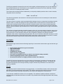
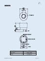
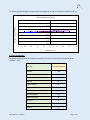
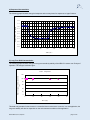
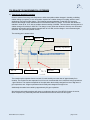
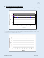
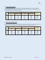
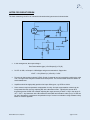
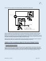
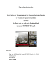
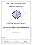
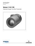
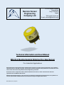
Nemoto Sensor
Engineering
Company Ltd
4-10-9 Takaido-Higashi
Suginami-ku
Tokyo 168-0072
Japan
Web: www.nemoto.eu
E-mail: [email protected]
Technical Information and User Manual
NE4-CL2 Electrochemical Chlorine (CL2) Gas Sensor
For Industrial Applications
Apart from pages 4 and 5 (Specification and Dimensions sections), the data in this document does not constitute a
specification but is intended as a guide, informing the instrument designer of the performance characteristics of the
sensor which were observed by Nemoto Sensor Engineering scientists.
It should be read in conjunction with the official datasheet for the device, which includes the full technical
specification for the NE4-CL2 Gas Sensor.
Nemoto Sensor Engineering Co. Ltd. has a policy of continuous development and improvement of its products. As
such the specification and data outlined in this document may be changed without notice.
NE4-CL2-Manual, Issue 4, Sept 2015
INTRODUCTION
Nemoto & Co. Ltd was established in 1941 and continues to develop unique technologies for Safety, Security
and Health markets worldwide. Using our unique experience of fine chemical preparation and printing, we were
able to enter the gas sensor market in 1979 with a range of high-quality hot-wire type sensors (pellistors).
Nemoto is now one of the world’s leading manufacturers of chemical sensors and has so far delivered over 30million devices to the market.
As a result of three years’ development at our Tokyo R&D centre, we released our first electrochemical gas
sensor in 2000.
The NE4-CL2 Gas Sensor is a 3-Electrode electrochemical gas sensor designed for the detection and
measurement of Chlorine (CL2) in the range 0-10 ppm, in a wide range of industrial and commercial safety
applications. By adhering to industry standards for size and connection orientation, the NE4-CL2 can be
retrofitted easily to existing product designs.
By using our experience of design for manufacture and our high volume production facilities in Japan and China,
we have successfully reduced the cost of the NE4-CL2 whilst being able to maintain the highest performance
quality.
PRINCIPLES OF OPERATION
PTFE membrane for gas inlet
Counter electrode
2H2O
4H+
HCl
Cl2
2H2O → 4H+ + O2 + 4e-
Current
2H+
Electrolyte
Working electrode
Load resistor
Reference electrode
Cl2 + 2H + 2e → 2HCl
+
-
2Cl2 + 2H2O→ 4HCl + O2
Potentiostat
The NE4-CL2 consists of 3 porous noble metal electrodes separated by an acidic aqueous electrolyte, housed
within a plastic (PPO) enclosure. An electrolyte reservoir ensures an excess of electrolyte is available at all
times, and the sensor is vented to ensure that the internal and external pressure of the sensor is always in
equilibrium.
In operation, gas enters the cell via the capillary and filter, and comes into contact with the ‘working’ electrode.
Any Chlorine present undergoes the following (reduction) reaction:
Cl2 + 2H+ +2e- → 2HCl
NE4-CL2-Manual, Issue 4, Sept 2015
- page 2 of 15 -
The HCl gas generated vents away from the cell via the capillary, whilst the hydrogen ions (H+) are supplied by
the electrolyte within the cell. The electrons (e-) are supplied by the external circuit via a metal strip in contact
with it, in the form of a small (nA) electric current.
The reaction at the working electrode is balanced by a reciprocal (oxidation) reaction at the ‘counter’ electrode,
using water from the electrolyte:
2H2O → O2 + 4H+ + 4eThe electrons generated in this reaction are removed by the external circuit via a metal strip in contact with the
counter electrode.
Thus when Chlorine is present, water is generated whilst Hydrogen ions are consumed at the working electrode,
whilst the water is re-used and hydrogen ions are generated at the counter electrode. At the same time, the
reaction at the working electrode consumes electrons, whilst the reaction at the counter electrode generates
electrons. By connecting the working and counter electrodes together via a special circuit, the flow of electrons
between the two electrodes may be measured as a nA level current signal proportional to the ppm concentration
of Chlorine.
The ‘reference’ electrode maintains the healthy operation of the cell. It is surrounded by electrolyte, sees no gas
and no current is allowed to be drawn from it. Its electrochemical potential hence always remains constant at a
level known as the “rest air potential” and this is used to regulate the potential of the working electrode,
regardless of the current it is generating during operation. The use of a reference electrode in this way (i.e. threeelectrode operation) helps to extend the working range of the sensor, improves linearity and results in a number
of performance benefits compared with similar sensors working with 2-electrodes only.
FEATURES
Electrochemical gas sensors have the following superiority to conventional semiconductor type and hot-wire type
gas sensors.
•
•
•
•
•
•
•
•
Linear output in proportion to gas concentration
High reproducibility
Highly gas specific
Unaffected by humidity
Stable output for long periods
Low power consumption because no heater is used (can be battery operated)
Small and lightweight (can be used in portable devices)
No mechanical structure so highly resistant to shocks and vibrations.
The NE4-CL2 has been developed from our accumulation of technologies in production of hot-wire type gas
sensors, long research experience into catalysts, fine printing, and assembling of sensors. The NE4-CL2 is
small and less-expensive, but has high sensitivity, long life, and leak-free performance even under severe
operating conditions.
Air vent
The electrolyte used for chemical sensors is very hygroscopic, i.e. it has affinity for water, and its volume varies
depending on ambient temperature and humidity. This variation causes pressure inside the sensor to rise and
fall. In the worst case the electrolyte may leak out of the sensor and damage the circuitry around it.
To prevent this, the NE4-CL2 utilizes an air vent capability. This maintains equilibrium between internal and
external pressures and allows the sensor to be used in any orientation and under high temperature and humidity
conditions.
NE4-CL2-Manual, Issue 4, Sept 2015
- page 3 of 15 -
SPECIFICATIONS:
Output signal
600 +/- 150nA/ppm Cl2
NOTE: The output signal of the NE4-CL2 sensor is of opposite polarity to other sensors of this type –
i.e. the signal is negative compared to (say) a standard CO or H2S sensor of the same type.
Zero offset in clean air
Response time (T90)
Repeatability
< +/- 0.2 ppm equivalent
(T90)
< 40 sec.
(Same day measurement)
< +/- 2%
Zero offset
< +/-0.2 ppm equivalent / year
Sensitivity to CL2
< +/- 2% signal / month
(Zero offset swing)
< +/-0.5ppm (-20°C to +50°C)
Long Term Stability
Temperature dependence
Minimum Detection Limit
0.1 ppm
In Service
-20°C to +50°C
Recommended in Storage
-0°C to +20°C
In Service
15 – 90%RH
(non-condensing)
Recommended in Storage
15 – 90%RH
(non-condensing)
Temperature range
Humidity range
Pressure range in service
0.9 – 1.1 atm
0 – 10 ppm
Detection range
Maximum Overload Range
Recommended load
resistor
10Ω
Recommended maximum
storage time
Warranty
NE4-CL2-Manual, Issue 4, Sept 2015
50 ppm
6 months
Against faulty workmanship or
materials
24 months
- page 4 of 15 -
DIMENSIONS:
Case Material
Cap Colour
Weight
NE4-CL2-Manual, Issue 4, Sept 2015
PPO
Bright Yellow
5 g (approx.)
- page 5 of 15 -
PERFORMANCE DATA
1) Linearity
0.0
-1.0
Output(µA)
-2.0
-3.0
-4.0
-5.0
-6.0
0
2
4
6
8
10
CL2 gas concentration (ppm)
2) Uncompensated Temperature Dependence:
The following graph illustrates the typical effect of temperature on the output signal of the NE4-CL2, for a sensor
calibrated at 20oC:
120
Typical Characteristics
Output (% of Signal @ 20 ˚C)
110
100
90
80
70
60
-30
-20
-10
0
10
20
30
40
50
60
Temperature (℃)
NE4-CL2-Manual, Issue 4, Sept 2015
- page 6 of 15 -
The following graph illustrates the typical effect of temperature on the zero offset of the NE4-CL2 sensor.
Zero temperature of NE-Cl2
2.0
1.5
Output (
equivalent ppm)
1.0
0.5
0.0
-0.5
-1.0
-1.5
-2.0
-30
-20
-10
0
10
20
30
40
50
60
Temperature (˚C)
3) Cross Sensitivities:
The following table gives cross sensitivity information for a variety of commonly encountered gases.
(Chlorine = 100)
Test Gas
% cross-sensitivity
Chlorine
100
Hydrogen Sulphide
NE4-CL2-Manual, Issue 4, Sept 2015
< -100
Hydrogen
0
Methane
0
Carbon dioxide
0
Nitrogen Dioxide
100
Sulphur dioxide
< -15
Nitric oxide (NO)
< -2
Carbon monoxide
0
Ammonia
0
Ethanol
0
Toluene
0
- page 7 of 15 -
4) Response Characteristics
The following graph illustrates the typical response and recovery times for exposures to 1ppm Chlorine:
0.2
0.1
Output (µA): CL2 1ppm
0.0
-0.1
-0.2
-0.3
-0.4
-0.5
-0.6
-0.7
-0.8
0
30
60
90
120
150
180
210
240
Time (sec)
5) Long-Term Drift Characteristics:
The following graph illustrates the typical Long term sensitivity stability of the NE4-CL2 sensor over 50 days of
operation. The test gas used was 1ppm.
Room Temperature
Ratio od signal at initial sensitivity
(%)
120
100
80
60
40
20
0
0
10
20
30
40
50
Time (day)
This data was generated in bench tests in a controlled clean environment. In service, in a real application, the
long term stability will also be dependent on the environmental conditions of the application.
NE4-CL2-Manual, Issue 4, Sept 2015
- page 8 of 15 -
TOLERANCE TO ENVIRONMENTAL EXTREMES
1) Tolerance to Humidity Transients
Chlorine sensors from many manufacturers are often susceptible sudden changes in humidity, exhibiting
sudden swings (or “spikes”) in zero offset when exposed to a sudden change in humidity, which in some
applications can result in false alarms. The following test was undertaken on the NE4-CL2 sensor to
measure the strength of this unwanted effect on the Nemoto NE4-CL2 sensor. The sensor was allowed to
stabilize in clean air at 19°C, with an ambient relative humidity of 24%RH. Then the sensor was exposed to a
sudden change of humidity to 100% RH. The change in zero offset was observed. Once the zero offset had
stabilized, the humidity was suddenly changed back to 24% RH, and the change in zero offset was again
observed. The cycle was repeated 3 times.
The resulting plot is shown below:
RH 24
% RH 24
%
RH 24
%
Humidity dependence
RH 100
%
RH 100
%
RH 100
%
The transient spike response from the sensor for each humidity excursion was of approximately 5s in
duration. The results here are expressed in mV from our recommended circuit, with 6mV being equivalent to
1 ppm Chlorine. The maximum amplitude of the spike when the humidity changed from low to high was 1.1
ppm equivalent, and -0.5ppm equivalent when humidity was changed from high to low.
Additionally the settled zero varied by approximately 0.3 ppm equivalent.
We believe that humidity transients will cause no problems to the user of the NE4-CL2 sensor in service,
which compares very favourably with other electrochemical Chlorine sensors in this regard.
NE4-CL2-Manual, Issue 4, Sept 2015
- page 9 of 15 -
2) Tolerance to Temperature and Humidity Extremes
The following graph illustrates the signal output stability for a sensor exposed to +50° in dry air (< 40%RH)
over 50 days. The CL2 concentration used was 1ppm CL2 in air.
50℃ < 40%RH
Ratio od signal at initial sensitivity
(%)
120
100
80
60
40
20
0
0
10
20
30
40
50
Time (day)
The following graph illustrates the signal output stability for a sensor exposed to -20°C over 40 days. The CL2
concentration used for testing was 1ppm CL2 in air.
NE4-CL2-Manual, Issue 4, Sept 2015
- page 10 of 15 -
3) Tolerance to thermal shock
The following table shows the zero and sensitivity change following an exposure to -20°C for 30 minutes,
followed immediately with an exposure to +50°C for 30 minutes. This 60 minute cycle was repeated 10 times.
The gas concentration used for testing was 10ppm.
No.
1
2
3
4
5
Before temperature cycling
Zero offset in air
Sensitivity to
(µA)
10ppm CL2 (µA)
0.08
-6.72
-0.07
-6.79
0.10
-5.88
-0.07
-5.89
-0.07
-6.05
After temperature cycling
Zero offset in air
Sensitivity to
(µA)
10ppm CL2 (µA)
0.04
-6.68
0.05
-6.79
0.10
-6.00
0.03
-5.89
0.05
-6.04
Sensitivity
variation ratio
(%)
99.4
100.6
102.5
101.9
99.8
4) Tolerance to mechanical shock
The following table shows the zero and sensitivity change following a drop test: The sensor was dropped from a
height of 1m on to a concrete floor 5 times. The gas concentration used for testing was 10ppm.
Before test (micro A)
After test (micro A)
No.
Zero offset in air
(µA)
Sensitivity to
10ppm CL2 (µA)
Zero offset in air
(µA)
Sensitivity to
10ppm CL2 (µA)
Sensitivity
variation ratio
(%)
1
2
3
4
5
-0.06
-0.07
-0.06
-0.06
-0.05
-6.34
-6.45
-5.93
-6.65
-6.02
-0.07
-0.06
-0.04
-0.07
-0.06
-6.43
-6.76
-6.00
-6.84
-6.01
101.4
104.8
101.2
102.8
99.8
NE4-CL2-Manual, Issue 4, Sept 2015
- page 11 of 15 -
NOTES FOR CIRCUIT DESIGN
The basic measuring circuit for all 3-electrode electrochemical gas sensors is shown below:
counter
4 8
Reference
2
-
3
+
6
7 1
Working
FET
V
RG
RL
4 8
2
3
-
Output Voltage
6
+
7 1
•
In this arrangement, the output voltage =
Gas Concentration (ppm) x Cell Output (A) x RG (Ω)
•
So if RG is 100k, cell output is -600nA/ppm and gas concentration is 10ppm then
VOUT = 10 x (600x10-9) x (100x103) = 0.60V
•
RL is the cell load resistor (typically 5-50Ω). Speed of response can be increased by reducing the value
of RL, but signal noise may be increased as a consequence. The recommended values are shown on
sensor datasheets
•
Amplifiers should be high quality precision low input offset types, e.g. OP90 or similar
•
Some sensors require temperature compensation circuitry. A simple compensation network can be
incorporated into this circuit by replacing RG with a thermistor matrix. Typically this uses an NTC
thermistor that has 3435K of B constant adjusting the output accuracy to within ± 10% in the range of 10oC ∼ 50oC. Any thermistor with a B-constant around 3500K and resistance value (R25) of 10 KΩ can
be used. Alternatively, temperature compensation may of course be undertaken using software lookup
tables or a best fit algorithm.
NE4-CL2-Manual, Issue 4, Sept 2015
- page 12 of 15 -
The circuit Nemoto employs for all its internal testing of the NE4-CL2 is shown below:
0. 1μ F
- Vcc
0. 1μ F
R
10kΩ
4
C
8
NE-Cl2
2
6
3
7
54. 9kΩ
1
W
OP97
TH
0. 1μ F
12kΩ
+Vcc
non.
10μ F
- Vcc
0. 1μ F
4
Out put Vol t age
8
10Ω
2
6
3
7
1
OP97
0. 1μ F
10Ω
TH : NTC Ther mi st or
R = 10kΩ B = 3435k
103AT( I shi zuka El ect r oni c Cor p. )
25
+Vcc
Nemoto recognises that the companies who use its gas sensing devices are themselves experts in circuitry
design, often with more expertise than Nemoto in this area. The information given here is hence for initial
guidance only, and Nemoto does not insist that instrument designers reproduce our circuitry guidance precisely.
If the instrument designer deviates from this guidance significantly, however, Nemoto advises that we should be
consulted to ensure that the proposed circuit design will function correctly.
Failure to broadly adhere to the recommended circuitry concept outlined in this document without consultation
with Nemoto may result in the suspension of the warranties which apply to the device.
GENERAL NOTES ON HANDLING, MANUFACTURE AND INSTRUMENT DESIGN
1) Long-term drift of gas sensitivity
All electrochemical gas sensors lose sensitivity over time due to small changes on the surface of the working
electrode, reducing its oxidation capability. To reduce this, the NE4-CL2 uses a newly developed electrode
catalyst that will not deteriorate by more than 10% / year. Typically, these changes are limited to less than 10%
but we recommend that this deterioration should be taken into account when designing application circuits.
NE4-CL2-Manual, Issue 4, Sept 2015
- page 13 of 15 -
2) Environmental effects on gas sensitivity
Due to the hygroscopic nature of the electrolyte used in electrochemical sensors, moisture is absorbed from or
released to the surrounding atmosphere. In high humidity moisture is absorbed, causing an increased sensitivity.
In low humidity moisture is released back to the atmosphere and the sensitivity decreases. Conventional
electrochemical gas sensors show annual variation of gas sensitivity as much as 10 ∼ 20%.
The NE4-CL2 utilises an advanced electrolyte management design and, combined with the unique electrode
catalyst structure, these changes can be greatly reduced. Under normal operating conditions, gas sensitivity
should change by no more than ± 5% of the output value. The NE4-CL2 is designed so that all changes due to
moisture uptake/release are completely reversible.
If the gas intake area of the sensor is blocked with water drops or other liquid, gas cannot enter the sensor. The
NE4-CL2 is fitted with an integral hydrophobic barrier to prevent this, but we recommend the use of additional
membrane barriers if the sensor in highly condensing RH conditions.
CL2 gas is heavier than air, and will therefore fall to low levels in most applications. CL2 detecting devices should
be therefore be installed at low levels, provided it is safe to do so.
If the sensor is to be used in more irregular atmospheres, please contact us for assistance.
3) Storage of sensors
Electrochemical sensors should be stored in a clean air under room temperature, preferably 0oC ∼ 20oC and in
non-condensing RH conditions. The maximum storage period would be 6 months after delivery. For sensors
stored for more than 6 months, the life in service will be shortened by the excess storage period. Unlike
semiconductor type or hot-wire type gas sensors, the gas sensitivity of electrochemical gas sensors will change
as time passes regardless of whether sensor has been used or not.
4) Mounting of sensors
Electrode pins must be connected correctly to ensure operation.
If a thermistor is used for temperature compensation, it must be located near the sensor and away from heat
sources such as transformers.
The NE4-CL2 can be mounted in any orientation.
NE4-CL2 connection pins should not be soldered as excess heating may cause the deformation of the housing
and eventually leakage of electrolyte.
5) Calibration and gas testing
Calibration of detectors or densitometers should be done after the output value has been stabilized in clean air.
Evaluation of gas sensitivity should be made with clean air as the balance gas. When a test gas is blown directly
to the gas intake area, higher gas sensitivity may be observed. It is therefore best to test and calibrate gas
detection instruments and sensors in diffusion mode. This can be achieved by using a suitable test housing
where a low flow rate is used (< 1l/min) and where the air is agitated to ensure equal gas diffusion throughout.
Note that Nemoto’s own internal testing systems place the sensor in a large chamber, with the gas introduced by
injection. The chamber includes a fan which gently agitates the gas inside the chamber to ensure the test gas is
fully mixed with the air and does not stratify in the chamber. In this way, Nemoto’s own testing very closely
simulates the action of the sensor in a typical application.
NE4-CL2-Manual, Issue 4, Sept 2015
- page 14 of 15 -
Other methods, including the use of flow-through hoods and pumped sampling assemblies, may of course be
used by instrument manufacturers, but it should be recognised that the method used to expose the sensor to test
gas will have a small effect on the accuracy and repeatability of the results obtained, and the correlation of these
results with Nemoto’s own routine QA test results.
6) Other
Unless otherwise advised by Nemoto, voltage should not be supplied directly to the electrode pins.
Do not bend the pins.
Do not apply more than 5 Kg/cm2 of force to the sensor.
Take care not to block the gas intake area as it may prevent gas entering the sensor.
Never put foreign material in the gas intake area as it may cause the electrolyte leakage
Do not expose the sensor to excess vibration or shock.
If the sensor housing is damaged, do not use the sensor.
If the sensor is exposed to a high concentration of the target gas for a long period, the output signal may require
time to recover to normal operation.
Do not blow organic solvents, paints, chemical agents, oils, or high concentration gases directly onto sensors.
Do not disassemble the sensor as this may cause electrolyte leakage.
DEFINITIONS
Baseline / Baseline shift: Baseline means the output level in clean air. The output current value at 20oC would
be less than +/-120nA, but this tends to change as the ambient temperature rises higher than 30oC. The
Baseline shift means this variation of the output level, i.e. a maximum of 750nA, would be put out at 50oC. This
Baseline shift should be taken into account to optimise overall accuracy. In this manual, the output values are
calculated to be equivalent to CL2 gas concentrations.
Gas sensitivity / Output signals: Using the NE4-CL2, 600 ± 150nA is generated at 1ppm of CL2 gas. For
instance, the generated current value will be about 6µA at 10ppm of CL2 gas (10ppm x 600nA). This generated
current is generally recorded as a voltage produced by a Current – Voltage converting circuit as illustrated in our
recommended circuit, as the conversion is done through a resistor of 10 KΩ.
Response time (T90): This is the time taken to reach to 90% of the maximum output value in clean air.
Repeatability: This is the maximum variation of output signals when tests are repeated under the same
measuring conditions (temperature, humidity, gas concentration etc.). The repeatability of NE4-CL2 is ± 2%, and
this means that all of the test results would fall in the range of 98% ∼ 102%.
Temperature dependence: All electrochemical sensors are affected by changes in the ambient temperature
and the output increases as the ambient temperature rises. This is caused by the rate of oxidation reaction on
the surface of the catalyst, the dispersibility of the gas in the capillary, and the thermal effects on the mobility of
ions in the electrolyte. This temperature dependency can be compensated relatively easily by using a NTC
thermistor.
NE4-CL2-Manual, Issue 4, Sept 2015
- page 15 of 15 -