1
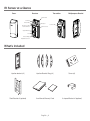
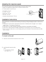
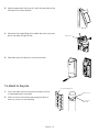
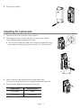
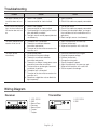
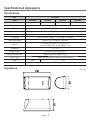
User Manual IR Sensor SIA-0010I/0010/0030/0060 Important Safety Instructions 1. Read these instructions. 2. Keep these instructions. 3. Heed all warnings. 4. Follow all instructions. 5. Do not use this apparatus near water. 6. Clean only with dry cloth. 7. Do not block any ventilation openings, Install in accordance with the manufacturer’s instructions. 8. Do not install near any heat sources such as radiators, heat reaisters, stoves, or other apparatus (including amplifiers) that produce heat. 9. Do not defeat the safety purpose of the polarized or grounding-type plug, A polarized plug has two blades with one wider than the other. A grounding type plug has two blades and a third grounding prong. The wide blade or the third prong are provided for your safety, If the provided plug does not fit into your outlet, consult an electrician for replacement of the obsolete outlet. 10. Protect the power cord from being walked on or pinched particularly at plugs, convenience receptacles, and the point where they exit from the apparatus. 11. Only use attachments/ accessories specified by the manufacturer. 12. Use only with the cart, stand, tripod, bracket, or table specified by the manufacturer, or sold with the apparatus. When a cart is used. Use caution when moving the cart/apparatus combination to avoid injury from tip-over. 13. Unplug this apparatus during lighting storms or when unused for long periods of time. 14. Refer all servicing to qualified service personnel. Servicing is required when the apparatus has been damaged in any way, such as power-supply cord or plug is damaged, liquid has been spilled or objects have fallen into the apparatus, the apparatus has been exposed to rain or moisture, does not operate normally, or has been dropped. English _1 WARNING TO REDUCE THE RISK OF FIRE OR ELECTRIC SHOCK, DO NOT EXPOSE THIS PROCUCT TO RAIN OR MOISTURE. DO NOT INSERT ANY METALLIC OBJECT THROUGH THE VENTILATION GRILLS OR OTHER OPENNINGS ON THE EQUIPMENT. Apparatus shall not be exposed to dripping or splashing and that no objects filled with liquids, such as vases, shall be placed on the apparatus CAUTION CAUTION RISK OF ELECTRIC SHOCK. DO NOT OPEN CAUTION : TO REDUCE THE RISK OF ELECTRIC SHOCK. DO NOT REMOVE COVER (OR BACK). NO USER SERVICEABLE PARTS INSIDE. REFER SERVICING TO QUALIFIED SERVICE PERSONNEL. EXPLANATION OF GRAPHICAL SYMBOLS The lightning flash with arrowhead symbol, within an equilateral triangle, is intended to alert the user to the presence of “dangerous voltage” within the product’s enclosure that may be of sufficient magnitude to constitute a risk of electric shock to persons. The exclamation point within an equilateral triangle is intended to alert the user to the presence of important operating and maintenance (servicing) instructions in the literature accompanying the product. Class construction An apparatus with CLASS construction shall be connected to a MAINS socket outlet with a protective earthing connection. Battery Batteries(battery pack or batteries installed) shall not be exposed to excessive heat such as sunshine, fire or the like. Disconnection Device Disconnect the main plug from the apparatus, if it’s defected. And please call a repair man in your location. English _2 When used outside of the U.S., it may be used HAR code with fittings of an approved agency is employed. CAUTION These servicing instructions are for use by qualified service personnel only. To reduce the risk of electric shock do not perform any servicing other than that contained in the operating instructions unless you are qualified to do so. Please read the following recommend safety precautions carefully. y Do not Place this apparatus on an uneven surface. y Do not install on a surface where it is exposed to direct sunlight, near heating equipment or heavy cold area. y Do not place this apparatus near. y Do not attempt to service this apparatus yourself. y Do not place a glass of water on the product. y Do not install near any magnetic sources. y Do not block any ventilation openings. y Do not place heavy items on the product. User’s Manual is a guidance book how to use the products The meaning of the using sign in the book is following y Reference: in case of providing information for helping of product’s usages y Notice: If there’s any possibility to occur any damages for the goods and human caused by not following the instruction Ú Please read this manual for the safety before using of goods and keep it in the safe place. English _3 IR Sensor at a Glance Cover Receiver Transmitter Multipurpose Bracket Alarm LED Terminal Good LED Response Time Control Wheel Temper Power LED Monitor Jack Sight Window Lens Vertical Angle Adjustable Screw What’s Included Injection bracket (x2) Injection Bracket Wing (x4) Screw (x4) + Steel Bracket x2 (optional) User Manual/Warranty Card English _4 U-shaped Bracket x2 (optional) Adjusting the response speed You can adjust the response time by turning the response time control wheel left or right. Turning it left will speed up the response time; turn it right to slow down the time. The factory default is set to 250 msec. • • • • • Full-speed run – 50 msec Fast walk – 100 msec Normal walk – 250 msec Slow walk – 350 msec Jump over a fence or obstacle – 500 msec 50 msec 500 msec Installation Instructions For best performance, you should consider the followings when placing, installing and keeping the product at a distance from the object. • Do not expose it to a place where its light projector or light receiver is affected by a direct strong light such as sunlight or headlight. (below ±2 is not allowed in the optical axis) • Do not install it in an unstable, not properly secured place. (wire fence or unsecured pole is not allowed) • Do not install it in a place where the infrared light is blocked due to a seasonal reason such as thick wood or bushes. • Keep it away from the muddy water or sea water keeping splashing. (the infrared light is likely to be blocked by the muddy water or sea water) Installation To mount on the wall 1. Loosen the screw to remove the cover of the sensor as shown. 2. Insert the bracket wing on the side as shown. If using more than 1 bracket (max. height 15 cm) English _5 3. Hook the upper hole of the sensor first and fit the lower hole into the wall bracket in the arrow direction. 4. Remove the slot-shaped filling on the rubber hole of the sensor and pull out the cables through the hole. Rubber Hole 5. When done, adjust the optical axis and insert the cover. To attach to the pole Pole bracket (Optional) 1. Pull out the cables from the wiring hole of the pole; insert the U-shaped pole bracket to the pole. 2. Attach the sensor to the bracket and arrange the cables as necessary. (same as in wall-mounting) English _6 Cable-In Hole Pole bracket (Optional) 3. Put the cover as original. Adjusting the optical axis 1. Connect both transmitter and receiver and turn them on. 2. Look through the mirror of the sight and adjust the sensor so that the other sensor can be positioned in the center of the mirror. You can use the left/right adjustable screw and the vertical adjustable screw of the reflector to refine your adjustment. (vertically ±10˚ & horizontally ±90˚) ±10˚ ±90˚ 3. Check the level of the light received from the monitor output signal. You can use the tester to measure the DC voltage and refine your adjustment. 4. Check the output voltage of the tester and close the cover. Output Voltage Optical Axis Status 3.0V or higher Good 2.9V or lower To be adjusted English _7 Troubleshooting Problem Reason Action The power indicator of the transmitter does not turn on. 1. Power is not supplied. 2. Loose connection or short-circuited 1. Apply the power. 2. Check if the cables are properly connected. Even if I block the infrared light, the alarm indicator of the receiver does not turn on. 1. Power is not supplied. 2. Loose connection or short-circuited 3. The infrared light is incoming to the receiver after reflected by an object. 4. Two light sources are not properly blocked simultaneously. 1. Turn on the sensor. 2. Check if the cables are properly connected. 3. Remove the interruption object, or change the installation site or the orientation of the optical axis. 4. Block two light sources simultaneously. The alarm indicator of the receiver will not turn off. 1. The optical axis is dislocated. 2. There exists an obstacle between transmitter and receiver. 3. The cover of the transmitter or receiver has impurities on it. 1. Adjust the optical axis as necessary. 2. Remove the obstacle. 3. Wipe out the impurities with a soft cloth. The alarm sounds intermittently. 1. Disconnected cables 2. Fluctuation of the power voltage 3. There exists an obstacle between transmitter and receiver. 4. There exists a different strong power source around the transmitter or receiver. 5. The transmitter or receiver gets loose and unstable at its position. 6. The optical axis is dislocated. 7. The cover of the transmitter or receiver has impurities on it. 8. Sometimes a big bird or cat can block the light temporarily. 1. 2. 3. 4. 5. 6. 7. 8. Check the connection status again. Regulate the power voltage. Remove the obstacle. Change the wiring path. Secure the pole or support. Adjust the optical axis as necessary again. Wipe out the impurities with a soft cloth. Set the response time longer. Wiring Diagram Receiver Transmitter 1. VCC : DC12V 2. GND 3. Normal Close 4. Common 5. Normal Open 6. Tamper 7. Tamper 1. VCC : DC12V 2. GND English _8 Specifications & Appearance Specifications Item Description Model SIA-0010I SIA-0010 SIA-0030 SIA-0060 Work Range Outdoor 10m Outdoor 10m Outdoor 30m Outdoor 60m Detection System NIR Blocking System (Twin Beams) IR Light IR LED Response Time 50 ~ 500 ms Power Voltage DC 12V(±15%) AGC Voltage Alarm: 2.0V or less, Ready: 2.1~2.9V, Good: 3.0V or higher Current Consumption Receiver: 19mA, Transmitter: 22mA (max) Alarm Out Dry contact relay output 1C (COM, N.C/N.O) Reset: Interruption time + off-relay (approx. 1 sec) Temperature -25˚C ~ 60˚C Temper Output Dry contact, Micro SW (COM, N.C) Adjustment of Optical Axis Horizontal: 180˚(±90˚), vertical: 20˚(±10˚) Bracket Type Default: Wall-mount bracket, Optional: Pole-mount bracket Weight 454g 470g Dustproof/Waterproof Rating IP 65 Appearance Unit: mm English _9 Correct Disposal of This Product (Waste Electrical & Electronic Equipment) (Applicable in the European Union and other European countries with separate collection systems) This marking on the product, accessories or literature indicates that the product and its electronic accessories (e.g. charger, headset, USB cable) should not be disposed of with other household waste at the end of their working life. To prevent possible harm to the environment or human health from uncontrolled waste disposal, please separate these items from other types of waste and recycle them responsibly to promote the sustainable reuse of material resources. Household users should contact either the retailer where they purchased this product, or their local government office, for details of where and how they can take these items for environmentally safe recycling. Business users should contact their supplier and check the terms and conditions of the purchase contract. This product and its electronic accessories should not be mixed with other commercial wastes for disposal. P/No. : Z6806119001A-00