1
Operator's Manual
CRFIFrSMAN°
10 in. COMPOUND MITER SAW
AND STAND WITH LASER TRAC ®
Model No. 137.212310
i
CAUTION:
Before using this Miter Saw,
read this manual and follow
all its Safety Rules and
Operating Instructions
Customer
Help
For Technical
Support
•
•
Operation
Maintenance
•
Parts List
Repair
1-800-843-1682
Parts
Center
1-800-488-1222
Estates, IL 60179 USA
Visit our Craftsman website: www.sears.com/craftsman
Part No. 137212310001
Sn_ftetlYalt_s_
ruct i° n s
Sears
Line
Sears, Roebuck and Co., Hoffman
:
&
SECTION
PAGE
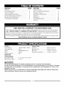
Warranty .............................................................
2
Product Specifications
........................................
SECTION
PAGE
Carton Contents ..................................................
7
2
Know Your Compound Miter Saw .......................
8
Power Tool Safety ..............................................
Compound Miter Saw Safety ..............................
3
4
Glossary of Terms ...............................................
Assembly and Adjustments .................................
9
10
Electrical Requirements and Safety ....................
Accessories and Attachments ............................
4
6
Operation ............................................................
Maintenance .......................................................
17
24
Tools Needed for Assembly ................................
6
Troubleshooting Guide ........................................
Parts List .............................................................
25
26
ONE-YEAR
FULL WARRANTY
ON CRAFTSMAN
TOOL
If this Craftsman tool fails due to a defect in material or workmanship within one year from the date of purchase,
CALL 1-800-4-MY-HOME® TO ARRANGE FOR FREE REPAIR (or replacement if repair proves impossible).
If this tool is used for commercial or rental purposes, this warranty will apply for only ninety days from the date of
purchase. This warranty applies only while this tool is in the United States.
This warranty gives you specific legal rights, and you may also have other rights, which vary, from state to state.
Sears, Roebuck
and Co., Hoffman
MOTOR
Power Source ......................
Arbor Shaft Size ..................
120V AC, 60Hz, 15 Amp
5/8 in.
Speed ..................................
4800 RPM (No load)
Brake ...................................
Electric
Double Insulated .................. Yes
MITER SAW
Estates,
IL 60179
Rotating Table:
Crosscut ...................................
2-5/8 in. x 5-1/2 in.
Miter 45 ° R & L .........................
Bevel 45 ° L ...............................
2-5/8 in. x 3-1/2 in.
1-9/16 in. x 5-1/2 in. L
45 ° Miter and 45 ° Bevel ............ 1-9/16 in. x 3-1/2 in.
Cutting Capacity:
Miter Detent Stops ................ 0 °, 15°, 22.5°, 31.6°, 45° R & L
Bevel Positive Stops ............. 0 °, 45 ° L
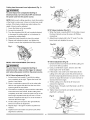
WARNING I
To avoid electrical hazards, fire hazards or damage to the tool, use proper circuit protection.
This tool is wired at the factory for 110-120 Volt operation. It must be connected to a 110-120 Volt / 15 Ampere
time delay fuse or circuit breaker. To avoid shock or fire, replace power cord immediately if it is worn, cut or
damaged in any way.
Before using your tool, it is critical that you read and understand these safety rules. Failure to follow these
rules could result in serious injury to you or damage to the tool.
GENERAL
BEFORE
SAFETY
INSTRUCTIONS
USING THIS POWER
TOOL
Safety is a combination of common sense, staying alert
and knowing how to use your power tool.
WARNING J
To avoid mistakes that could cause serious injury,
do not plug the tool in until you have read and
understood the following.
READ and become familiar with the entire
Operator's Manual. LEARN the tool's application,
limitations and possible hazards.
2.
KEEP GUARDS IN PLACE and in working order.
3
REMOVE ADJUSTING KEYS AND WRENCHES.
Form the habit of checking to see that keys and
adjusting wrenches are removed from the tool
before turning ON.
4.
5.
6.
KEEP WORK AREA CLEAN. Cluttered areas and
benches invite accidents.
12. ALWAYS WEAR EYE PROTECTION. Any power
tool can throw foreign objects into the eyes and
_ _
could cause permanent eye damage.
ALWAYS wear Safety Goggles (not
that comply with ANSI Safety
standard Z87.1 Everyday eyeglasses
have only impact-resistant lenses.
They ARE NOT safety glasses. NOTE: Glasses or
goggles not in compliance with ANSI Z87.1 could
seriously injure you when they break.
13. WEAR A FACE MASK OR DUST MASK. Sawing
operation's produce dust.
14. SECURE WORK. Use clamps or a vise to hold work
when practical. It is safer than using your hand and
it frees both hands to operate the tool.
15. DISCONNECT TOOLS FROM POWER SOURCE
before servicing and when changing accessories
such as blades bits and cutters.
16. REDUCE THE RISK OF UNINTENTIONAL
STARTING. Make sure switch is in the OFF position
before plugging the tool in.
DO NOT USE IN DANGEROUS ENVIRONMENTS.
Do not use power tools in damp locations, or expose
them to rain or snow. Keep work area well lit.
17. USE RECOMMENDED ACCESSORIES. Consult
this Operator's Manual for recommended
accessories. The use of improper accessories may
cause risk of injury to yourself or others.
KEEP CHILDREN AWAY. All visitors and
bystanders should be kept a safe distance from
work area.
18. NEVER STAND ON THE TOOL. Serious injury
could occur if the tool is tipped or if the cutting tool
is unintentionally contacted.
7.
MAKE WORKSHOP CHILD PROOF with padlocks,
master switches or by removing starter keys.
8.
DO NOT FORCE THE TOOL. It will do the job better
and safer at the rate for which it was designed.
9.
USE THE RIGHT TOOL. Do not force the tool or an
attachment to de a job for which it was not designed.
10. USE PROPER EXTENSION CORDS. Make sure
your extension cord is in good condition. When
using an extension cord, be sure to use one heavy
enough to carry the current your product will draw.
An undersized cord will result in a drop in line
voltage and in loss of power which will cause the
tool to overheat. The table on page 5 shows the
correct size to use depending on cord length and
nameplate ampere rating. If in doubt, use the next
heavier gauge. The smaller the gauge number, the
heavier the cord.
11. WEAR PROPER APPAREL. Do not wear loose
clothing, gloves, neckties, rings, bracelets or other
jewelry which may get caught in moving parts.
Nonslip footwear is recommended. Wear protective
hair covering to contain long hair.
19. CHECK FOR DAMAGED PARTS. Before further
use of the tool, a guard or other part that is damaged
should be carefully checked to determine that it will
operate properly and perform its intended function
- check for alignment of moving parts, binding of
moving parts, breakage of parts, mounting and
any other conditions that may affect its operation.
A guard or other part that is damaged should be
properly repaired or replaced.
20. NEVER LEAVE THE TOOL RUNNING
UNATTENDED. TURN THE POWER "OFF". Do
not walk away from a running tool until the blade
comes to a complete stop and the tool is unplugged
from the power source.
21. DO NOT OVERREACH. Keep proper footing and
balance at all times.
22. MAINTAIN TOOLS WITH CARE. Keep tools
sharp and clean for best and safest performance.
Follow instructions for lubricating and changing
accessories.
23. WARNING: Dust generated from certain materials
can be hazardous to your health. Always operate
saw in well-ventilated area and provide for proper
dust removal.
SPECIFIC
SAFETY
THIS COMPOUND
INSTRUCTIONS
FOR
MITER SAW
DO NOT USE THIN KERF BLADES they can
deflect and contact guard and can cause possible
injury to the operator.
2.
3.
4.
5.
6.
7.
8.
9.
18. MAKE SURE the blade is not contacting the
workpiece before the switch is turned ON.
19. IMPORTANT: After completing the cut, release
the trigger and wait for the blade to stop before
returning the saw to the raised position.
DO NOT operate the miter saw until it is completely
assembled and installed according to these
instructions.
20. MAKE SURE the blade has come to a complete
stop before removing or securing the workpiece,
changing the workpiece angle or changing the angle
of the blade.
IF YOU ARE NOT thoroughly familiar with the
operation of miter saws, seek guidance from your
supervisor, instructor or other qualified person.
21. NEVER cut metals or masonry products with this
tool. This miter saw is designed for use on wood
and wood-like products.
ALWAYS hold the work firmly against the fence and
table. DO NOT perform any operation free hand
(use clamp wherever possible).
22. NEVER cut small pieces. If the workpiece being cut
would cause your hand or fingers to be within 6-3/4
in. of the saw blade the workpiece is too small.
KEEP HANDS out of the path of the saw blade. If
the workpiece you are cutting would cause your
hands to be within 6-3/4 in. of the saw blade, the
workpiece should be clamped in place before
making the cut.
23. PROVIDE adequate support to the sides of the saw
table for long work pieces.
BE SURE the blade is sharp, runs freely and is free
of vibration.
25. NEVER use solvents to clean plastic parts. Solvents
could possibly dissolve or otherwise damage the
material.
ALLOW the motor to come up to full speed before
starting a cut.
KEEP THE MOTOR AIR SLOTS CLEAN and free
of chips or dust.
ALWAYS MAKE SURE all handles are tight before
cutting, even if the table is positioned in one of the
positive stops.
10. BE SURE both the blade and the collar are clean
and the arbor bolt is tightened securely.
11. USE only blade collars specified for your saw.
12. NEVER use blades larger in diameter than 10
inches.
13. NEVER apply lubricants to the blade when it is
running.
14. ALWAYS check the blade for cracks or damage
before operation. Replace a cracked or damaged
blade immediately.
15. NEVER use blades recommended for operation at
less than 4800 RPM.
16. ALWAYS keep the blade guards in place and use at
all times.
17. NEVER reach around the saw blade.
24. NEVER use the miter saw in an area with flammable
liquids or gases.
26. SHUT OFF the power before servicing or adjusting
the tool.
27. DISCONNECT the saw from the power source and
clean the machine when finished using.
28. MAKE SURE the work area is clean before leaving
the machine.
29. SHOULD any part of your miter saw be missing,
damaged, or fail in any way, or any electrical
component fail to perform properly, lock the switch
and remove the plug from the power supply outlet.
Replace missing, damaged, or failed parts before
resuming operation.
I =1ai
|-'t ::( LuJ
I-'1::l vAI
::l i
POWER SUPPLY AND MOTOR SPECIFICATIONS
The AC motor used in this saw is a universal,
nonreversible type. See "MOTOR" in the "PRODUCT
SPECIFICATIONS" section on page 2.
WARNING J
To avoid electrical hazards, fire hazards, or damage
to the tool, use proper circuit protection. Your saw
is wired at the factory for 120 V operation. Connect
to a 120 V, 16 A circuit and use a 16 A time delay
fuse or circuit breaker. To avoid shock or fire, if
power cord is worn or cut, or damaged in any way,
have it replaced immediately.
ELECTRICAL
REQUIREMENTS
- cont'd
DOUBLEINSULATED[]
4.
The power tool is double insulated to provide a double
thickness of insulation between you and tool's electrical
system. All exposed metal parts are isolated from
the internal metal motor components with protecting
insulation.
Replacement parts - When servicing, use only
identical replacement parts.
5.
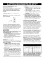
Polarized plugs - This saw has a plug that looks like
the one shown below:
To reduce the risk of electrical shock, this saw has a
polarized plug (one blade is wider than the other). This
plug will fit in a polarized outlet only one way. If the plug
does not fit fully in the outlet, reverse the plug. If it still
does not fit, contact a qualified electrician to install the
proper outlet. Do not change the plug in any way.
IA WARNING I
Double insulation does not take the place of normal
safety precautions when operating this tool.
To avoid electrocution:
1. Use only identical replacement parts when servicing
a tool with double insulation. Servicing should be
performed by a qualified technician.
2. Do not use power tools in wet or damp locations or
expose them to rain or snow.
MOTOR SAFETY PROTECTION
IMPORTANT
To avoid motor damage, the motor should be blown out
or vacuumed frequently to keep sawdust from interfering
with the motor ventilation.
1. Connect this saw to a 120 V circuit. This circuit
must not be less than a #12 wire with a 20 A time
lag fuse or a #14 wire with a 15 A time lag fuse.
NOTE: When using an extension cord on a circuit
with a #14 wire, the extension cord must not exceed
25 feet in length.
2. If the motor will not start, release the trigger switch
immediately. UNPLUG THE SAW. Check the saw
blade to make sure it turns freely. If the blade is free,
try to start the saw again. If the motor still does not
start, refer to the TROUBLESHOOTING GUIDE.
3. If the tool suddenly stalls while cutting wood, release
the trigger switch, unplug the tool and free the blade
from the wood. The saw may now be started and
the cut finished.
FUSES may "blow" or circuit breakers may trip
frequently if:
a. MOTOR is overloaded - overloading can occur
if you feed too rapidly or make too many start/
stops in a short time.
b. LINE VOLTAGE is more than 10% above or
below the nameplate voltage rating. For heavy
loads, the voltage at motor terminals must equal
the voltage specified on the nameplate.
c. IMPROPER or dull saw blades are used.
Most motor troubles may be traced to loose or
incorrect connections, overload, low voltage or
inadequate power supply wiring. Always check the
connections, the load and supply circuit if the motor
doesn't run well. Check minimum gauge for the
length of cord you are using on the chart below.
GUIDELINES FOR EXTENSION CORDS
Use a proper extension cord. Make sure your extension
cord is in good condition. When using an extension
cord, be sure to use one heavy enough to carry the
current your product will draw. An undersized cord will
cause a drop in line voltage, resulting in loss of power
and overheating. The table below shows the correct size
to use depending on cord length and nameplate ampere
rating. If in doubt, use the next heavier gauge. The
smaller the gauge number, the heavier the cord.
Be sure your extension cord is properly wired and
in good condition. Always replace a damaged extension
cord or have it repaired by a qualified person before
using it. Protect your extension cords from sharp
objects, excessive heat and damp or wet areas.
Use a separate electrical circuit for your tools, This
circuit must not be less than a #12 wire with a 20 A
time lag fuse era #14 wire with a 15 Atime lag fuse.
NOTE: When using an extension cord on a circuit with
a #14 wire, the extension cord must not exceed 25 feet
in length. Before connecting the tool to the power line,
make sure the switch is in the OFF position and the
electric current is rated the same as the current stamped
on the motor nameplate, running at a lower voltage will
damage the motor.
(When using 120 volts only)
Ampere Rating
Total length of Cord
More Than
Not More Than 25ft. 50ft.
100ft. 150ft.
0
6
8
16
16
14
6
10
8
16
14
12
10
12
6
16
14
12
CAUTION: In all cases make certain the receptacle in
question is properly grounded, If you are not sure,
have a certified electrician check the receptacle.
RECOMMENDED
ACCESSORIES
Supplied
Not supplied
I_ WARNING I
•
Use only accessories recommended
for this
miter saw. Follow instructions that accompany
accessories. Use of improper accessories may
cause hazards.
•
Blade Wrench
Adjustable Wrench
The use of any cutting tool except 10 in. saw
Hex Key
blades which meet the requirements under
recommended accessories is prohibited. Do
not use accessories such as shaper cutters or
•
dado sets. Ferrous metal cutting and the use of
abrasive wheels is prohibited.
Do not attempt to modify this tool or create
accessories not recommended for use with
Combination
this tool. Any such alteration or modification
is misuse and could result in a hazardous
Square
Philips Screwdriver
condition leading to possible serious injury.
Screwdriver
ACCESSORIES
Visit your Sears Hardware Department or see the
Sears Power and Hand Tool Catalog to purchase
recommended accessories for this power tool.
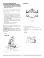
COMBINATION
SQUARE
Should not gap or overlap when square is flipped over
(see dotted figure).
Straight edge or
a 3/4 in. board,
IAWARNING
To avoid the risk of personal injury, do not modify this
power tool or use accessories not recommended by
Sears.
MUST BE TRUE
Draw light line on board
along this edge.
this edge must be
perfectly straight.
WARNING I
Read warnings and conditions on your CARBIDE TIPPED
SAW BLADE. Do not operate the saw without the proper
saw blade guard in place. Carbide is a very hard but
brittle material. Care should be taken while mounting,
using, and storing carbide tipped blades to prevent
accidental damage. Slight shocks, such as striking the
tip while handling, can seriously damage the blade.
Foreign objects in the workpiece, such as wire or nails,
can also cause tips to crack or break off. Before using,
always visually examine the blade and tips for bent
blade, cracks, breakage, missing or loose tips, or other
damage. Do not use if damage is suspected. Failure
to heed safety instructions and warnings can result in
serious bodily injury.
Gap from untrue square
when flipped over.
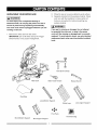
UNPACKING
YOUR
MITER SAW
2.
3.
IA WARNING I
items are accounted for, before discarding any
packing material.
To avoid injury from unexpected starting or
electrical shock, do not plug the power cord into a
source of power during unpacking and assembly.
This cord must remain unplugged whenever you are
Place the saw on a secure stationary work surface.
Separate all parts from the packing material. Check
each one with the illustration to make certain all
la, WARNING
I
working on the saw.
If any part is missing or damaged, do not attempt
to assemble the miter saw, or plug in the power
1. Remove the miter saw from the carton.
cord until the missing or damaged part is correctly
replaced. To avoid electric shock, use only identical
replacement parts when servicing double insulated
tools.
IMPORTANT: Do not lift miter saw by the Trigger
Switch handle. It may cause misalignment.
Blade Wrench
Dust Bag
X
Long Bottom Support
Stand Legs
Long Upper Support
Foot Pads
Hardware Bag
Short Bottom Support
Short Upper Support
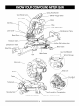
CuttingHeadHandle
UpperBlade
ON/OFFTriggerSwitch
Cover
DustBac
Blade
LowerBladeGuard
LaserGuide
htExtension
Table
BevelScale
Hold-down
Claml:
PositiveStopLockingLever
LeftExtension
Table
Handle
Stop
Base
Laser On/Off Switch
MiterScale
Wrench Storage
ArborLock
Latch
Table
Pivot
Bolt
Table
Lock Nut
\
Mounting
Hand Location for Transportation
Positive Miter Detents
Table Lock Knob
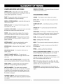
COMPOUND
MITER SAW TERMS
ARBOR LOCK - Allows the user to keep the blade
from rotating while tightening or loosening the arbor bolt
during blade replacement or removal.
BASE - Supports the table, holds accessories and
allows for workbench or leg set mounting.
BEVEL LOCKING HANDLE - Locks the miter saw at a
WRENCH STORAGE - Convenient storage to prevent
misplacing the blade wrench.
WOODWORKING
TERMS
ARBOR - The shaft on which a blade is mounted.
BEVEL CUT - An angle cut made through the face of
the workpiece.
desired bevel angle.
BEVEL SCALE - To measure the bevel angle of the
saw blade 0 ° to 45 ° left.
COMPOUND
cut.
OUT - A simultaneous bevel and miter
CROSS CUT - A cut made across the width of the
COVER PLATE SCREW - Loosen this screw and rotate
workpiece.
the plate for access to the blade arbor bolt.
FENCE - Helps to keep the workpiece from moving
when sawing. Scaled to assist with accurate cutting.
FREEHAND - Performing a cut without using a fence
(guide), hold down or other proper device to prevent the
workpiece from twisting during the cutting operation.
LOWER BLADE GUARD - Helps protect your hands
from the blade in the raised position, it retracts as the
blade is lowered.
GUM - A sticky sap from wood products.
MITER HANDLE - Used to rotate the table, and to
rotate the saw to a right or left cutting position.
KERF - The amount of material removed by blade cut.
MITER SCALE - Measures the miter angle 0 ° to 45 ° left
and right.
HEEL - Misalignment of the blade.
MITER CUT - An angle cut made across the width of
the workpiece.
RESIN - A sticky sap that has hardened.
MOUNTING HOLES - To mount the miter saw to a
stable su trace.
ON/OFF TRIGGER SWITCH - To start the tool,
squeeze the trigger. Release the trigger to turn off the
miter saw.
REVOLUTIONS PER MINUTE (RPM) - The number of
turns completed by a spinning object in one minute.
SAW BLADE PATH - The area of the workpiece or
table top directly in line with the travel of the blade or the
part of the workpiece which will be cut.
POSITIVE STOP LOCKING LEVER - Locks the miter
saw at a preset positive stop for the desired miter angle.
STOP LATCH - Locks the miter saw in the lowered
SET - The distance between two saw blade tips, bent
outward in opposite directions to each other. The further
apart the tips are, the greater the set.
position for compact storage and transportation.
SWITCH HANDLE - The switch handle contains
the trigger switch and the laser on/off switch. The blade
is lowered into the workpiece by pushing down on the
handle. The saw will return to its upright position when
the handle is released.
WARNING LABELS - Read and understand for your
own safety. Make sure all labels are present on machine
and legible.
WORKPIECE - The item being cut. The surfaces of a
workpiece are commonly referred to as faces, ends and
edges.
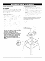
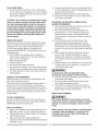
ASSEMBLY INSTRUCTIONS
ASSEMBLE MITER SAW TO STAND
1,4 WARNING I
1.
2.
To avoid injury, do not connect this miter saw to the
power source until it is completely assembled and
adjusted and you have read and understood this
Carefully place the miter saw on top of stand.
Line up the four mounting holes in the saw base to
the stand.
3.
Fasten the saw to the stand using the four mounting
bolts (9), four washers (10) and four nuts (11 ).
Operator's Manual.
NOTE: Place a washer on each bolt before inserting
it into the saw base and through the support, then
thread the nut onto the bolt. (see Fig. A)
ASSEMBLE STAND (FIG. A)
1.
2.
3.
4.
5.
Unpack all parts and group by type and size. Refer
to the parts list on page 29 for correct quantities.
Attach one long upper support (4) to top of leg (1)
using one carriage bolt (2) and nut (5).
NOTE: Do not tighten bolts until stand is properly
aligned (see step #8).
Attach other end of long upper support to the top of
Tighten all four nuts.
NOTE: DO NOT OVER TIGHTEN THE LOCK NUTS
HOLDING SAW TO THE STAND. THIS COULD
DAMAGE THE SAW BASE.
Fig. A
another leg using one carriage bolt and one nut.
Attach one long bottom support (3) to the center of
each leg using carriage bolt and nut. This completes
the front frame section.
Assemble the rear frame section in exactly the same
manner.
6.
Join the front and rear frame assemblies using
7.
two short upper supports (6) and two short bottom
supports (8), carriage bolts and nuts.
Place all four foot pads (7) onto each leg.
8.
4.
Place the stand on a level surface and adjust it so
all legs are contacting the floor and are at similar
angles to the floor and detents in stand leg align
with support bracket, then tighten all bolts.
NOTE: Stand should not rock after all bolts are
tightened.
9_
Saw Base (saw not
shown for clarity of view).
10_
I
I
>
/
7
/
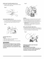
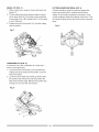
INSTALLING THE MITER HANDLE (FIG. B)
Fig, D
1. Thread the miter handle (1) into the hole (2) located
at the front of the miter table.
Fig, B
t
1
Locking
When transporting or storing the miter saw, the cutting
SAW BLADE WRENCH (FIG. C)
head should always be locked in the down position.
1. Push the cutting head (3) down to its lowest position.
2. Push the stop latch (2) into the locking hole (4).
IMPORTANT: To avoid damage, never carry the
1. For convenient storage and prevention of loss, there
is a slot (1) in the rear of the cutting head handle (2)
for storing the blade wrench (3) when not in use.
miter saw by the switch handle, the cutting arm or
the miter table handle.
Fig. C
2
1
INSTALLING
THE DUST BAG (FIG. E)
1. Squeeze the metal collar wings (2) of the dust bag (1).
2. Place the dust bag neck opening around the exhaust
port (3), and release the metal collar wings.
Fig. E
2
3
CUTTING HEAD (FIG. D)
Raising
1. Push down slightly on the cutting handle (1).
2. Pull out the stop latch knob (2).
3. Allow the cutting head (3) to raise to the up position.
IA WARNING[
To avoid injury and damage to the saw, transport
or store the miter saw with the cutting head locked
in the down position. Never use the stop latch to
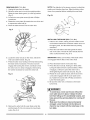
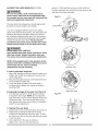
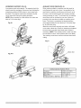
REMOVING OR INSTALLING THE BLADE
la, WARNING
I
hold the cutting head in a down position for cutting
operations.
Only use a 10-inch diameter blade.
To avoid injury from an accidental start, make sure
the switch is in the OFF position and plug is not
connected to the power source outlet.
11
REMOVING
(FIG.F, G, G-l)
1. Unplugthesawfromtheoutlet.
2. Allowthemitersawto risetotheuprightposition.
Raisethelowerbladeguard(1)totheupposition.
(Fig.F)
3. Loosenthecoverplatescrew(2)witha Phillips
screwdriver.
4. Rotatethecoverplate(3)towardstherearofthetool
toexposethearborbolt(4).
5. Placethebladewrenchoverthearborbolt.
Fig.F
NOTE: Pay attention to the pieces removed, noting their
position and direction they face. Wipe the blade collars
clean of any sawdust before installing the new blade.
Fig, G-1
6
8
1
2
INSTALLING
THE BLADE (FIG. F, G, G-l)
1. Install a 10 in. blade, making sure the rotation arrow
on the blade matches the clockwise rotation arrow on
the upper guard, and the blade teeth are pointing
downward.
2. Place the outer blade collar (6) against the blade
and on the arbor. Thread the arbor bolt (8) into the
arbor counterclockwise. (Fig. G-l)
/
IMPORTANT:
6. Locate the arbor lock (5) on the motor, below the
miter saw switch handle. (Fig. G)
7. Press the arbor lock, holding it in firmly while turning
the blade wrench clockwise. The arbor lock will
Make sure the flats of the blade collars
are engaged with the flats on the arbor shaft.
3. Place the blade wrench on the arbor bolt.
4. Press the arbor lock (5), holding it in firmly while
turning the blade wrench counterclockwise. When
engage after turning the wrench. Continue to hold
the arbor lock in to keep it engaged, while turning
the wrench clockwise to loosen the arbor bolt.
it engages, continue to press the arbor lock in,
while tightening the arbor bolt securely. (Fig. G)
5. Rotate the cover plate (3) back until the slot in the
Fig, G
cover plate engages with the cover plate screw
(2). Tighten the screw with a Phillips screwdriver.
Lower the blade guard.
6. Be sure the arbor lock is released so the blade
tu ms freely.
IA WARNING
I
•
To avoid injury, never use the saw without the
cover plate secure in place. It keeps the arbor
bolt from falling out if it accidentally loosens, and
helps prevent the spinning blade from coming off
the saw.
•
Make sure the collars are clean and properly
arranged. Lower the blade into the table and
check for any contact with the metal base or the
turn table.
8. Remove the arbor bolt (8), outer blade collar (6),
and the blade (7). Do not remove the inner blade
collar. (Fig. G-l)
12
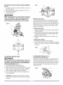
INSTALLING THE HOLD-DOWN CLAMP ASSEMBLY
(FIG. H)
Fig. I
2
1
1. Loosen the lock handle knob (3) from the rear side of
the saw base (4).
2. Place the hold-down clamp assembly (1) in one of
the mounting holes (2).
3. Tighten the knob.
IAk WARNING I
When
clamp
clamp
cause
using stop block on the right side, hold-down
must also be in right side. Using hold-down
on the left side during this operation can
kickback and serious injury to the operator.
MITER SCALE (FIG. J)
The miter scale assists the user in setting the desired
miter angles from 47 ° left to 47 ° right. The miter saw
table has nine of the most common angle setttings with
positive stops at 0 °, 15 °, 22.5 °, 31.6 °, and 45 °. These
positive stops position the blade at the desired angle
quickly and accurately.
Fig. H
To Adjust the Angle:
1. Unlock the miter table by turning the miter handle (1)
counterclockwise.
2. Press down the positive stop locking lever (2) while
holding the miter handle, and rotate the table left or
right to the desired angle.
3. Release positive stop locking lever. Tighten miter
handle.
1
To Adjust the Indicator:
1. Position the miter table at zero degrees.
2. Loosen the pointer screw (4) and adjust the indicator
(3) to the 0 ° mark on the miter scale (5) and retighten
the screw.
Fig, J
ADJUSTMENT
CUTTING ARM TRAVEL (FIG, K)
Cutting arm pivot adjustment
The up and down pivot movement of the cutting arm (1)
should not be too tight, restricting movement, nor too
loose, affecting the accuracy of the saw cut. The correct
locking nut (2) adjustment is snug, allowing no side-toside arm movement. To adjust, tighten or loosen the
adjusting nut (2).
INSTRUCTIONS
WARNING I
To avoid injury from an accidental start, make sure
the switch is in the OFF position and the plug is not
connected to the power source outlet.ADJUSTING
FENCE SQUARENESS (FIG. I)
1. Loosen the two fence locking bolts (1).
2. Lower the cutting arm and lock in position.
3. Using a square, lay the heel of the square against the
blade, and the rule against the fence (2) as shown.
Check to see if the fence is 90 ° to the blade.
Fig, K
4. If not, adjust fence 90 ° to the blade and tighten the
fence locking bolts.
4
CAUTION: If the saw has not been used recently,
recheck blade squareness to the fence and readjust
if needed.
13
Fig. M
Cutting head downward travel adjustment (Fig. L)
IA. WARNING [
To avoid injury from unexpected starting or
electrical shock, turn the switch OFF and remove
the power cord from the power source.
NOTE: Before each cutting operation, check the position
of the blade to make sure it does not contact any metal
surface. If the blade contacts any metal surface, the
depth of travel must be adjusted.
1. Lower the blade as far as possible.
2. Loosen the Iocknut (3).
3. Turn the adjustment bolt (4) out (counterclockwise)
900(0 °) Bevel indicator (Fig. M-1 )
1. When the blade is exactly 90°(0 °) to the table, loosen
the bevel indicator screw (5) using a #2 Phillips
screwdriver.
to decrease the cutting depth or in (clockwise) to
increase the cutting depth.
4. Rotate the blade manually to check for contact.
5. Repeat until adjusted properly, and tighten the
2. Adjust bevel indicator (6) to the "0" mark (7) on the
bevel scale and retighten the screw.
Iocknut to secure the adjustment bolt into position.
Fig, M-1
Fig. L
_.__
BEVEL STOP ADJUSTMENT
j4
45 ° Bevel adjustment
(Fig. N)
1. Unlock the bevel lock handle and tilt the cutting arm
as far to the left as possible.
(FIG. M & N)
IA. WARNING [
2. Using a combination square, check to see if the
blade angle is 45 ° to the table.
3. If the blade is not at 45 ° to the miter table, tilt the
To avoid injury from unexpected starting or
electrical shock, make sure the trigger is released
and remove the power cord from the power source.
cutting arm to the right, loosen the jamb nut (5) on
the bevel angle adjustment bolt (4) and use a 10 mm
wrench to adjust the bolt (4) in or out to increase or
decrease the bevel angle.
900(0 °) Bevel adjustment (Fig. M)
1. Loosen bevel lock handle (1) and tilt the cutting
arm completely to the right. Tighten the bevel lock
handle. Lower blade.
4. Tilt the cutting arm to the left to 45 ° bevel and
recheck for alignment.
5. Repeat steps 1 through 4 until the blade is at 45 ° to
the miter table.
2. Place a combination square (2) on the miter table
with the rule against the table and the heel of the
square against the saw blade.
3. If the blade is not 90°(0 °) square with the miter table,
loosen the bevel lock handle, tilt the cutting head
6. Tighten bevel lock handle and jamb nut (5) when
alignment is achieved.
completely to the left, loosen the jamb nut (4) on the
bevel angle adjustment bolt (3) and use a 10 mm
wrench to adjust the bolt (3) in or out to increase or
decrease the bevel angle.
Fig, N
4. Tilt the cutting arm to back to the right at 90°(0 °)
bevel and recheck for alignment.
5. Repeat steps 1 through 4 if further adjustment is
needed.
6. Tighten bevel lock handle and jamb nut (4) when
alignment is achieved.
14
5
MOUNTING THE MITER SAW (FIG. O)
Stationary Use
To avoid injury from unexpected saw movement:
• Before moving the saw, disconnect the power cord
from the outlet, and lock the cutting arm in the lower
position using the stop latch.
NOTE: The stop latch is for carrying or storing the tool.
It is not to be used for holding the saw while cutting.
Lower blade and press in stop latch to secure saw for
transport or storage.
• Never carry the miter saw by the power cord or by
the switch handle. Carrying the tool by the power
cord could cause damage to the insulation or wire
connections resulting in electric shock or fire.
• To avoid injury from flying debris, do not allow visitors
to stand behind the saw.
• Place the saw on a firm, level work-surface where
there is room for handling and properly supporting
the workpiece.
• Support the saw on a level work surface.
• Bolt or clamp the saw to its support.
Place the saw in the desired location, either on a work
bench or recommended leg set. The base of the saw
THE LASER GUIDE (FIG, P)
1. To turn laser on, press on/off rocker switch (1) to
"ON " position.
2. To turn off laser, press on/off rocker switch to" OFF"
has three mounting holes (1).
For stationary use, fasten the saw to a workbench.
For portable use, fasten the saw to a 3/4 in. piece of
plywood. This mounting board can then be clamped to a
secure surface.
position.
Fig, P
Fig, 0
Protable Use
Hand Location for
3/4 Inch Plywood
Transportation
15
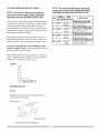
ALIGNING THE LASER BEAM (FIG. P-l, P-2)
screws (1). Start with the set screw on the left side of
the laser assembly, then with the front set screw on the
I_ WARNING I
right side of the laser assembly.
For your own safety, never connect the plug to
power source outlet until all the adjustment steps
are complete and you have read and understood the
safety and operational instructions.
Fig. P-1
The laser beam must always be correctly aligned with
the blade to ensure straight, even cutting.
Laser Switch
Your tool is equipped with the Laser Trac ° cutting
guide using Class Ilia laser beams. The laser beam will
enable to preview the saw blade path on the stock to
be cut before starting the miter saw. This laser guide is
powered by the transformed alternating current supply
directly through the power lead. The saw must be
connected to the power source and the laser on/off
switch must be turned on for the laser line to show.
IAWARNING
AVOID DIRECT EYE CONTACT
Laser radiated when laser guide is turned on. Avoid
direct eye contact. Always un-plug the miter saw
from power source before making any adjustments.
NOTE: All the adjustments
for the operation
of this
machine have been completed
at the factory. Due to
normal wear and use, some occasional
readjustments
may be necessary.
Left Side View
A. Check Laser Beam Alignment,
1. Mark a 90 ° straight line across a board to serve as a
"pattern line" to test laser alignment. Lay the board
on the miter table.
2. Plug saw into outlet and turn on the laser beam and
line it up with the pattern line.
3. Lower saw blade to pattern line and if blade is
not flush with the pattern line, adjust as follows in
procedures (B).
Right Side View
B. Adjusting the Angle of the Laser Trac ® (Fig. P-2)
1. Turn the laser element (1) in the desired direction
to adjust the laser angle. NOTE: Do not adjust the
laser more than _Aturn in either direction as this may
damage the laser. There are two flat sides on the
laser element where you can position an adjustable
wrench for your adjustment.
Fig. P-2
C, Aligning The Laser Beam
1. Loosen only Y2turn at a time the three set screws (1).
2. Adjust laser by turning the left side set screw
clockwise to shift the laser line to the right. To shift
the laser line to the left, turn the right side set screws
Y2turn at a time.
3. Once alignment of the laser is achieved,
tighten only Y2turn at a time the three set
16
SAFETY INSTRUCTIONS
OPERATION
FOR BASIC SAW
BEFORE USING THE MITER SAW
•
1,4 WARNING I
•
To avoid mistakes that could cause serious,
permanent injury, do not plug the tool in until the
following steps are completed:
•
Completely assemble and adjust the saw,
following the instructions. (ASSEMBLY AND
ADJUSTMENTS)
•
Learn the use and function of the ON/OFF trigger
switch, on/off switch for laser, upper and lower blade
guards, stop latch, bevel lock handle, and cover
plate screw.
•
Review and understand all safety instructions and
operating procedures in this Operator's Manual.
(SAFETY & OPERATIONS)
•
Reviewthe MAINTENANCE and
•
•
•
•
•
•
•
•
ACCESSORIES
Consult the ACCESSORIES
and ATTACHMENTS
section of this Operators Manual for recommended
accessories. Follow the instructions that come with
TROUBLESHOOTING GUIDE for your miter saw.
To avoid injury or possible death from electrical
shock:
•
Make sure your fingers do not touch the plug's metal
prongs when plugging or unplugging your miter saw.
(ELECTRICAL REQUIREMENTS AND SAFETY)
•
the accessory. The use of improper accessories
may cause risk of injury to persons.
Choose the correct 10 in. diameter blade for the
material and the type of cutting you plan to do. Do
not use thin kerf blades.
Disconnect the miter saw. To avoid injury from
•
accidental starting, unplug the saw before any
adjustments, including set-up and blade changes.
Compare the direction of rotation arrow on the
guard to the direction arrow on the blade. The blade
teeth should always point downward at the front of
the saw.
•
Make sure the blade is sharp, undamaged and
properly aligned. With the saw unplugged, push
the cutting arm all the way down. Manually spin the
blade and check for clearance. Tilt the cutting arm
to 45 ° bevel and repeat the test.
Make sure the blade and arbor collars are clean.
Make sure all clamps and locks are tight and there
is no excessive play in any parts.
KEEP YOUR WORK AREA CLEAN
Cluttered areas and benches invite accidents.
Tighten the arbor bolt.
Tighten the cover plate screw,
Check for damaged parts, Check for:
• Alignment of moving parts
• Damaged electric cords
• Binding of moving parts
• Mounting holes
• Function of arm return spring and lower guard:
Push the cutting arm all the way down, then let
it rise until it stops. The lower guard should fully
close. Follow instructions in TROUBLE-
WARNING J
To avoid burns or other fire damage, never use the
miter saw near flammable liquids, vapors, or gases.
•
Plan ahead to protect your eyes, hands, face and
ears.
•
SHOOTING GUIDE for adjustment if necessary.
• Other conditions that may affect the way the
miter saw works.
•
turning it on.
To avoid injury from jams, slips, or thrown pieces,
use only recommended accessories.
RECOMMENDED
BEFORE EACH USE INSPECT YOUR SAW.
•
missing, bent, damaged or broken in any way, or
any electrical parts don't work, turn the saw off and
unplug it.
Replace bent, damaged, missing or defective parts
before using the saw again.
Maintain tools with care. Keep the miter saw clean
for best and safest performance. Follow instructions
for lubricating. Don't put lubricants on the blade
while it's spinning.
Remove adjusting wrench from the tool before
•
Keep all guards in place, in working order and
proper adjustment. If any part of this miter saw is
17
Know your miter saw. Read and understand the
Operator's Manual and labels affixed to the tool.
Learn its application and limitations as well as the
specific potential hazards peculiar to this tool. To
avoid injury from accidental contact with moving
parts, don't do layout, assembly, or setup work on
the miter saw while any parts are moving.
Avoid accidental starting
Make sure the trigger switch is disengaged before
plugging the miter saw into a power outlet.
PLANYOURWORK
• Usetherighttool.Don'tforcea toolor attachment
to doa jobit wasnotdesignedtodo.Usea different
toolforanyworkpiece
thatcan'tbeheldina solidly
braced,fixedposition.
•
•
•
CAUTION: This machine is not designed for cutting
masonry, masonry products, ferrous metals (steel,
iron, and iron-based metals.) Use this miter saw to
cut only wood, wood-like products, or non-ferrous
metals. Other material may shatter, bind the blade,
or create other dangers. Remove all nails that may
be in the workpiece to prevent sparking that could
cause a fire. Remove dust bag when cutting nonferrous metals.
USE EXTRA CAUTION WITH LARGE OR ODD
SHAPED WORKPIECES.
•
•
DRESS FOR SAFETY
•
Any power tool can throw foreign objects into the eyes.
This can result in permanent eye damage. Everyday
eyeglasses have only impact resistant lenses and
are not safety glasses. Glasses or goggles not in
compliance with ANSI Z87.1 could seriously injure you
when they break.
• Do not wear loose clothing, gloves, neckties or
jewelry (rings, watches). They can get caught and
draw you into moving parts.
• Wear non-slip footwear.
• Tie back long hair.
• Roll long sleeves above the elbow.
• Noise levels vary widely. To avoid possible hearing
damage, wear ear plugs when using any miter saw.
• For dusty operations, wear a dust mask along with
safety goggles.
•
•
Use extra supports (tables, sawhorses, blocks, etc.)
for workpieces large enough to tip.
Never use another person as a substitute for a
table extension, or as an additional support for a
workpiece that is longer or wider than the basic
miter saw table, or to help feed, support, or pull the
workpiece.
Do not use this saw to cut small pieces. If the
workpiece being cut would cause your hand or
fingers to be within 6-3/4 inches of the saw blade
the workpiece is too small. Keep hands and fingers
out of the "no hands zone" area marked on the saws
table.
When cutting odd shaped workpieces, plan your
work so it will not bind in the blade and cause
possible injury. Molding, for example, must lie flat
or be held by a fixture or jig that will not let it move
when cut.
Properly support round material such as dowel rods,
or tubing, which have a tendency to roll when cut,
causing the blade to "bite".
[,A WARNING J
To avoid injury, follow all applicable safety
instructions, when cutting non-ferrous metals:
• Use only saw blades specifically recommended for
non-ferrous metal cutting.
• Do not cut metal workpieces that must be hand
held. Clamp workpieces securely.
• Cut non-ferrous metals only if you are under the
supervision of an experienced person and the dust
bag has been removed from the saw.
INSPECT YOUR WORKPIECE
Make sure there are no nails or foreign objects in the
part of the workpiece being cut.
Plan your work to avoid small pieces that may bind, or
that are too small to clamp and get a solid grasp on.
Plan the way you will grasp the workpiece from start to
finish. Avoid awkward operations and hand positions. A
sudden slip could cause your fingers or hand to move
into the blade.
WHEN SAW IS RUNNING
WARNING J
DO NOT OVER-REACH
Keep good footing and balance. Keep your face and
body to one side, out of the line of a possible kickback.
NEVER stand in the line of the blade.
Do not allow familiarity from frequent use of your
miter saw to result in a careless mistake. A careless
fraction of a second is enough to cause a severe
injury.
Never cut freehand:
•
Brace your workpiece firmly against the fence and
table stop so it will not rock or twist during the cut.
•
Make sure there is no debris between the workpiece
and the table or fence.
•
Keep the cut off piece free to move sideways after it
is cut off. Otherwise, it could get wedged against the
blade and thrown violently.
Only the workpiece should be on the saws table.
Secure work. Use clamps or a vise to help hold the
work when it's practical.
Before cutting, if the saw makes an unfamiliar noise
or vibrates, stop immediately. Turn the saw OFF.
Unplug the saw. Do not restart until finding and
correcting the problem.
Make sure there are no gaps between the
workpiece, fence and table that will let the workpiece
shift after it is cut.
18
BODY AND HAND POSITION (FIG. Q)
TURNING SAW ON (FIG. R)
WARNING I
*
WARNING
I
Never place hands near the cutting area. Proper
positioning of your body and hands when
operating the miter saw will make cutting easier
Make the switch child-proof. Insert a padlock
through the hole (2) in the trigger switch and lock
it. This will prevent children and other unauthorized
users from engaging the trigger switch ON.
and safer. Keep children away. Keep all visitors
at a safe distance from the miter saw. Make sure
bystanders are clear of the saw and workpiece,
This miter saw is equipped with an ON/OFF trigger
switch (1). When the trigger switch is squeezed, the
miter saw will be turned on.
Don't force the saw. It will do the job better and
safer at its designed rate.
Starting a cut:
• Place hands at least 6-3/4 in. away from the path of
the blade - out of the "no-hands zone" (1). (Fig. Q)
• Hold workpiece firmly against the fence to prevent
movement toward the blade.
•
With the power switch OFF, bring the saw blade
down to the workpiece to see the cutting path of the
blade.
•
•
Squeeze trigger switch to start saw.
Lower blade into workpiece with a firm downward
motion.
Fig. R
_
BEFORE LEAVING THE SAW
•
Finishing a cut:
• Hold the cutting arm in the down position.
• Release trigger switch and wait for all moving parts
to stop before moving your hands and
raising the cutting arm.
• If the blade doesn't stop within 6 seconds, unplug the
saw and follow the instructions in
TROUBLESHOOTING GUIDE section for
•
Never leave tool running unattended. Turn power
OFF. Wait for all moving parts to stop.
Make workshop child- proof. Lock the shop.
Disconnect master switches. Store tool away from
children and other unauthorized users.
MITER CUT (FIG. S)
1. When a miter cut is required, unlock the miter table
by turning the miter handle (1) counterclockwise.
2. While holding the miter handle, press down on the
positive stop locking lever (2) to disengage the
positive stop locking lever.
adjusting the blade brake before using the saw
again.
Before freeing jammed material:
• Release trigger switch.
• Wait for all moving parts to stop.
• Unplug the miter saw.
3. Rotate the miter table to the right or left with the miter
handle.
4. When the table is in the desired position as shown on
the miter scale (3), release the positive stop locking
lever handle and tighten the miter handle. The table
is now locked at the desired angle. Positive stops are
provided at 0°,15 ° , 22.5 ° , 31.6 ° and 45 °.
Fig. Q
IMPORTANT: ALWAYS TIGHTEN the miter table
lock handle before cutting.
Fig. S
No-Hands Zone
I
I
I
I
®,
6-3/4 in. ",;i '
6-3/4 in.
19
BEVEL CUT (FIG, T)
1. When a bevel cut is required, loosen the bevel lock
handle (1).
CUTTING BOWED MATERIAL (FIG. V)
A bowed workpiece must be positioned against the
fence and secured with a clamping device before
cutting. Do not position workpiece incorrectly or try to
cut the workpiece without the support of the fence. This
2. Tilt the cutting head to the desired angle as shown
on the bevel scale (2). The blade can be positioned
at any angle, from a 90 ° straight cut (0 ° on the scale)
to a 45 ° left bevel.
will cause the blade to bind and could result in personal
injury.
3. Tighten the bevel lock handle (1) to lock the cutting
head in position.
Fig. V
Fig. T
COMPOUND
CUT (FIG. U)
A compound cut is the combination of a miter and a
bevel cut simultaneously.
1. Loosen the bevel lock handle (1) and position the
cutting head at the desired bevel position. Lock the
bevel lock handle.
2. Loosen the miter table lock handle (2). Press down
the positive stop locking lever (3) and position the
table at the desired angle. Release the positive stop
locking lever and lock the miter handle.
Fig. U
20
WORKPIECE
SUPPORT
(FIG.W)
Longpiecesneedextrasupport.Thesupportshouldbe
placedundertheworkpiece.
Keepyourhandholdingthe
workpiecepositioned
6-3/4inchesor moreawayfrom
theblade.Thesupportmustlettheworkpiece
layflat
ontheworktableduringthecuttingoperation.
NOTE:Whenmountedona flatsurface,themitersaw
tableis 3-1/4incheshigh.
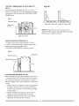
AUXlLARYWOODFENCE(FIG.X)
Whenmakingmultipleor repetitivecutsthatresultin
cut-off pieces of one inch or less, it is possible for the
saw blade to catch the cut-off piece and throw it out of
the saw or into the blade guard and housing, possibly
causing damage or injury. To minimize this, an auxiliary
wood fence can be mounted to your saw. Holes are
provided in the saw fence to attach an auxiliary wood
fence. This fence is constructed of straight auxiliary
wood approximately 3/4 inch thick by 2-1/2 inches high
by 16-1/8 inches long.
Attach the wood fence securely and make a full depth
cut to make a blade slot. Check for interference between
Fig.W
the wood fence and the lower blade guard. Adjust if
necessary. NOTE: This auxiliary fence is used only with
the saw blade in the 0° bevel position (90 ° to the table).
The auxiliary wood fence must be removed when bevel
cutting
Fig, X
3-1/4 in.
Slot
Fig. W-1
Cutting Capacity Auxiliary Fence
Crosscut
3-1/2 in. x 3-1/2 in
Miter 450 R & L
3-1/2 in. x 2 in
Bevel 450 L
2 in. x 3-2/1 in.
Compound 450L, 450R&L
21
2in. x2in.
CUTTINGA DIMENSIONAL
4X4 WITH ONE CUT
Fig. AA
(FIG. Y)
A dimensional 4x4 workpiece (3-1/2 in. x 3-1/2 in. )
may be cut in half with one cut by attaching an auxiliary
wood fence of 3/4 inch thick. See "AUXILIARY WOOD
FENCE" above
P
m
F
e
n
c
Fig, Y
Auxiliary Fence_
_
Miter Saw Table
3-1/2 in.
Miter Saw Table
miter at 45 °, bevel at 0° miter at 0°, bevel at 45 o
Miter Saw
Fence
_
\
I
3-1/2 in.
NOTE: Always perform a dry run cut so you can
determine if the operation being attempted is possible
before power is applied to the saw.
Miter Saw Table
VERTICAL MITER CUTTING (FIG. Z)
To make a miter cut in a 2x4 workpiece (1-1/2in. x
3-1/2in.) in the vertical position a spacer such as the
auxiliary wood fence described in the
"AUXILIARY WOOD FENCE" section is required.
Fig. Z
Auxiliary Fence.
Miter Saw
/Workp
_
ece
q
_1_"Z1/2 in_
CUTTING BASE MOLDING (FIG, AA)
Base moldings and many other moldings can be cut on
a compound miter saw. The setup of the saw depends
on molding characteristics and application, as shown.
Perform practice cuts on scrap material to achieve best
results:
1. Always make sure moldings rest firmly against fence
and table. Use hold-down or C-clamps, whenever
possible, and place tape on the area being clamped
to avoid marks.
2. Reduce splintering by taping the cut area prior to
making cut. Mark cut line directly on the tape.
3. Splintering typically happens due to wrong blade
application and thinness of the material.
CUTTING
CROWNMOLDING
(FIG.BB,CC)
NOTE: The chart below references a compound
cut for crown molding ONLY WHEN THE ANGLE
BETWEEN THE WALLS EQUALS EXACTLY 90 °.
Your compound miter saw is suited for the difficult task
of cutting crown molding. To fit properly, crown molding
must be compound-mitered with extreme accuracy.
The two surfaces on a piece of crown molding that fit
flat against the ceiling and wall are at angles that, when
added together equal exactly 90 °.
Most crown molding has a top rear angle (the section
that fits flat against the ceiling) of 52°and a bottom rear
angle (the section that fits flat against the wall) of 38 °.
NOTE: The chart below references a compound
cut for crown molding ONLY WHEN THE ANGLE
BETWEEN THE WALLS EQUALS EXACTLY 90 °.
KEYI SETTINGJ_SETTING
BEVEL I Miter l
TYPE OF CUT
Inside corner-Left side
IL
When setting the bevel and miter angles for compound
miters, remember that the settings are interdependent;
changing one changes the other, as well.
Fig, BB
FI
el
nl
Cl
el
Miter saw table
Bevel/Miter Settings
Fig, CC
Settings for standard crown molding lying flat on
compound miter saw table
Inside Corner
\
\
OR
\
Outside Corner
Compound Cut Crown Moldings
131.6°
J.Right
111.Position top of moldh/g against fence.
Miter lame set al RIGHT 31 6°.
L
LEFT side is finished
piece.
Inside corner-Right side
IR
OL
_33"9°
J33"9°
.LLeft131.6
°
J_Left
131.6°
111.Position bottoln of molding against fence.
Miter lable set at LEFT 31 6°
L
Outside
LEFT side is finished
J33.9°
131.6°
J_Right
piece.
corner-Left
side
111.Position bottom of molding against fence.
Miter table sel at LEFT 31 6°
L
RIGHT side is finished
Outside
OR
In order to accurately cut crown molding for a 90 °
inside or outside corner, lay the molding with its broad
back surface flat on the saw table.
133-9°
piece.
corner-Right
side
111.Position top of moldh/g against fence.
Miter lable sel at RIGHT 31 6°.
L
RIGHT side is finished
piece.
protection. Should the lower guard become damaged,
do not use the saw until the damaged guard has been
replaced. Develop a regular check to make sure the
lower guard is working properly. Clean the lower guard
of any dust or buildup with a damp cloth.
MAINTENANCE
IA
DANGER I
To avoid injury, never put lubricants on the blade
while it is spinning.
la, WARNING I
CAUTION: Do not use solvents on the guard. They
could make the plastic "cloudy" and brittle.
To avoid fire or toxic reaction, never use gasoline,
naphtha acetone, lacquer thinner or similar highly
volatile solvents to clean the miter saw.
I,a,WARNING
I
When cleaning the lower guard, unplug the saw from
the power source receptacle to avoid unexpected
startup.
I_ WARNING I
To avoid injury from unexpected starting or
electrical shock, unplug the power cord before
working on the saw.
I_k WARNING
SAWDUST
Periodically, sawdust will accumulate under the work
table and base. This could cause difficulty in the
movement of the worktable when setting up a miter cut.
Frequently blow out or vacuum up the sawdust.
I
For your safety, this saw is double-insulated. To
avoid electrical shock, fire or injury, use only
parts identical to those identified in the parts list.
Reassemble exactly as the original assembly to
avoid electrical shock.
la,WARNING
I
If blowing sawdust, wear proper eye protection to
keep debris from blowing into eyes.
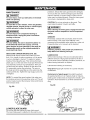
REPLACING CARBON BRUSHES (FIG. DD)
Replace both carbon brushes when either has less
than 1/4 in. length of carbon remaining, or if the spring
or wire is damaged or burned. To inspect or replace
brushes, first unplug the saw. Then remove the black
plastic cap (1) on the side of the motor (2). Remove the
cap cautiously, because it is springloaded. Then pull
out the brush and replace. Replace for the other side.
To reassemble reverse the procedure. The ears on
the metal end of the assembly go in the same hole the
carbon part fits into. Tighten the cap snugly, but do not
overtighten.
LUBRICATION
All the motor bearings in this tool are lubricated with a
sufficient amount of high grade lubricant for the life of
the unit under normal operating conditions; therefore, no
further bearing lubrication is required.
Lubricate the following as necessary:
Chop pivot: Apply light machine oil to points indicated
in illustration.
Central pivot of plastic guard: Use light household
oil (sewing machine oil ) on metal-to-metal or metal-toplastic guard contact areas as required for smooth, quiet
operation. Avoid excessive oil, to which sawdust will
cling.
NOTE: To reinstall the same brushes, first make sure
the brushes go back in the way they came out. This will
avoid a break-in period that reduces motor performance
and increases wear.
Fig. EE
Fig. DD
pivot of
plastic guard
LOWER
Chop pivo_
BLADE GUARD
Do not use the saw without the lower blade guard.
The lower blade guard is attached to the saw for your
24
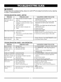
IA WARNING I
To avoid injury from accidental starting, always turn switch OFF and unplug the tool before moving, replacing
the blade or making adjustments.
TROUBLESHOOTING
GUIDE - MOTOR
PROBLEM
PROBLEM CAUSE
Brake does not
SUGGESTED CORRECTIVE ACTION
Motor brushes not sealed or lightly
sticking.
Motor brake overheated from use of
stop blade within 6
seconds.
defective or wrong size blade or rapid
ON/OFF cycling.
Arbor bolt loose.
4.
5.
Brushes cracked, damaged, etc.
Other.
2.
Limit switch failure
Brush worn.
3.
Brush spark when
switch released.
2.
TROUBLESHOOTING
PROBLEM
Blade hits table.
Angle of cut not
accurate. Can not
Fuse blown or circuit breaker tripped
on home panel.
Brush worn.
Other.
3. Retighten. See REMOVING OR INSTALLING
THE BLADE section.
4. Replace brushes.
5. Sears Service Center.
1. Replace limit switch.
2. Replace brushes. See MAINTENANCE section.
3. Verify there is electrical power at the outlet.
1. Replace Brushes. See MAINTENANCE
2. See Sears Service Center.
section.
GUIDE - SAW OPERATION
PROBLEM CAUSE
SUGGESTED CORRECTIVE ACTION
. Misalignment.
1. See ADJUSTMENT
. Miter table unlocked.
2. Sawdust under table,
- Cutting Arm Travel section.
1. See OPERATION - Miter Angle Adjustment
section.
adjust miter.
Cutting arm wobbles.
2. Use a recommended blade. Let cool down. See
REMOVING OR INSTALLING THE BLADE
section.
3.
Motor does not start
1. Inspect/clean/replace brushes. See
MAINTENANCE section.
2. Vacuum or blow out dust. WEAR EYE
PROTECTION.
1. See ADJUSTMENT - Cutting Arm Travel section.
. Loose pivot points.
Cutting arm will not
fully raise, or blade
guard won't fully
close.
. Pivot bolt too tight.
2. Pivot spring not replaced properly
after service.
3. Sawdust build-up.
1. Loosen pivot bolt lock nut (see adjustment
section).
2. Sears Service Center.
3. Clean and lubricate moving parts.
Blade binds, jams,
burns wood.
. Improper operation.
2. Dull or warped blade.
3. Improper blade size.
1. See BASIC SAW OPERATION section.
2. Replace or sharpen blade.
3. Replace with 10 in. diameter blade.
4 Wood is moving during cut.
Saw vibrates or
shakes.
4. Use hold down clamp to secure workpiece to
table.
. Saw blade not round / damaged / loose. 1. Replace blade.
2. Arbor bolt loose.
2. Tighten arbor bolt.
25
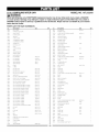
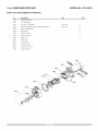
10 in. COMPOUND
MITER SAW
MODEL NO. 137.212310
WARNING I
When servicing use only CRAFTSMAN replacement parts, Use of any other parts many create a HAZARD
or cause product damage. Any attempt to repair or replace electrical parts on this Miter Saw may create a
HAZARD unless repair is done by a qualified service technician. Repair service is available at your nearest
Sears Service Center,
PARTS LIST FOR SAW SCHEMATIC
Size
QTY
QTY
I.D.
Description
I.D.
Description
Size
0824
PIVOT SHAFT
2457
FLAT WASHER
@10"22
2
(}828
ROTATION SLIDE PLATE
2948
WARNING
0831
SHAFT SLEEVE
21CH
CRRE
M5_08
10
081A
PLASTIC SLEEVE
23NF
ARBOR COLLAR
083S
TRIGGER
25TE
STOP BLOCK
(LEFT}
#23
083Z
CORD
25TF
STOP BLOCK
(RIGHT}
#23
OB5N
COMPRESSION
SPRING
26LU
WARNING
OCES
COMPRESSION
SPRING
290M
CAUTION
0CPD
CENTER BOLT
2BK3
ANGLE
0CV5
DUST BAG ASSAY
2BKK
CABLE SHIELD
OD7X
SHAFT
2BNF
LASER PLUNGER HOUSING
0D87
TORSION SPRING
2BP5
NEEDLE POINTER
OD?9
SHIM
2BP6
MITER LOCK HANDLE
0DRB
ANCHOR
2BPR
CABLE SHIELD
ODHT
SPRING GUARD
2BPV
CUTTER SHAFT GUARD
ODVJ
BLADE WRENCH
2BPW
NEEDLE POINTER
0J4F
FLAT WASHER
@8X16 25
2BXO
CRRE
0J43
FLAT WASHER
{RIOX20 2
2BX7
SLOTTED SET SCREW
OJ7R
FLAT WASHER
1/2 _1 3/64
2BXF
LASER
OJAZ
WAVE
WASHER
WW 6
2COF
CONTROLLER
0JBO
WAVE
WASHER
WW 8
2C 1A
POWER CABLE
(}JET
E RiNG
2C82
HEX HD
0JMM
O RiNG
2C88
BLADE
OJPE
HEX HD BOLT
M6_I 0 20
2CBD
CLEVIS PIN
OJPG
HEX HD. BOLT
M6*I 0 30
2CEE
CHIP PLATE
OJUK
HEX SOC
HD CAP BOLT
M6_I 0 16
2CBU
LOCK KNOB
OJZF
HEX SOC
SETSCREW
M6*I 0 10
2CAB
CR RE TRUSS HD ROUND NECK SCREW
M61
0JZN
ARBOR BOLT
M8*I 25 20
2CKJ
FENCE
#AW
0KOW
HEX HD SCREW AND
M6*I 0 25
2CR7
ARM
#AW
OK2N
HEX SOC
M8_I 25 25
2CS9
BEVEL LOCK KNOB
0K37
CRRE
M508
0K5C
CR RE COUNT
0K75
CR
OK7F
CR RE ROUND WASHER
HD SCREW
OK7K
CR RE ROUND WASHER
HD SCREW
0KA9
CRRE
PAN HD TAPPING
0KB7
CRRE
PAN HD TAPPING
OKBC
CRRE
OKBD
CRRE
0KD6
CLAMP
BLOCK
WASHER
HD CAP SCREW
PAN HD SCREW & WASHER
LABEL
PAN HD SCREW & WASHER
LABEL
LABEL
REGULATOR
#AW
#23
#AW
PAN HD SCREW & WASHER
M5_0.8
M61
ASSY
BOLT
M10"1 5 80
16
2CSB
MOTOR
M6_I 0 16
2CTE
LEAD WiRE ASBY
M6*I0
12
2CU6
LOWER BLADE GUARD
M5'08
8
2D47
LOCATOR
M6*I 0 12
2DRC
HANDLE
SCREW
M3'24
l0
2DAS
BRACKET TILT
f,
S_REW
M4X18
16
2DAT
SCALE
PAN HD TAPPING
f,
S_REW
M5*I6
25
2DAV
TILTING SCALE
PAN HD TAPPING
SCREW
M418
25
2DAW
TRADE MARK LABEL
CR RE PAN HD SCREW
M407
8
2DCF
WARNING
0KD7
CR RE PAN HD SCREW
M407
10
2DDQ
HANDLE
OKDG
CR RE PAN HD SCREW
M5"08
6
2DQ3
LEVER
OKDH
CR RE PAN HD SCREW
M508
8
2E3K
CR RE ROUND
0KDR
CR RE PAN HD SCREW
M5'08
10
2F3L
EXTENTION WING{LEFT)
#AW
0KDY
CR RE PAN HD. SCREW
M6*I 0 30
2F3M
EXTENTION WING (RIGHT}
#AW
OKL1
CRRE
M6_IO
2F3N
COIL SPRING
OKMS
HEX NUT
M6*I 0 T=5
2F3P
MITER ARM
#AW
0KQX
NUT
M6_I 0 T=6
2F46
BASE
#AW
0KC}Y
LOCK NUT
M81
2F4X
UPPER TUBE
#06
OKQZ
NUT
M101
2F4Y
UPPER TUBE
#06
OK RO
NUT
M 12_175 T=I 2
2F58
TABLE
#AW
0KUW
TERMINAL
2FDS
INSTRUCTION MANUAL
0LS9
LASER ON/OFF
2FT3
LABEL
OLU2
LIMIT SWITCH
2FUJ
TABLE INSERT
OQQ1
CORD
2FVB
BOLT CLAMP
0S1S
COLLAR
2FXl
HOLD DOWN
12BQ
WAVE
HD SCREW
RE TRUSS HD SCREW
PAN HD ROUND NECK SCREW
12
25 T=8
5 T=IO
ROCKER SWITCH
GUARD
WASHER
BWW 6303
26
80
0 8
0
12
ASS'Y
PIN
LABEL
WASHER HD SCREW
CLAMP
ASS'Y
M5"08
10
10 in. COMPOUND
MITER SAW
MODEL NO. 137.212310
SCHEMATIC FOR SAW
0KU_ 2
OKA9
2COF
OK_Ke
25TF
OJAZ_
2CS_0JMM
_v/_OjTR
OKRO
0JZN
2F3M
/
OKQX
2BPW
OKDH
2DAS
0824
.2BP5
081A
2DAV
10 in. COMPOUND
MITER SAW
PARTS LIST AND SCHEMATIC
MODEL NO. 137.212310
FOR MOTOR
Size
QTY
I.D.
Description
0HX9
NEEDLE BEARING
0JB8
WAVE WASHER
1
0JX3
HEX. SOC. SETSCREW
2
0KCN
CR.RE. PAN HEAD TAPPING & WASHER SCREW
2
0QQS
BRUSH HOLDER ASS'Y
2
0QQT
BRUSHASS'Y
2
0QR0
BRUSH COVER
2
2AKT
ARMATURE ASS'Y
1
2BPA
FIELD ASS'Y
1
2BPE
GEAR BOX
1
2BPF
FLOW GUIDE
1
2BPP
MOTOR COVER
1
2BX4
CUTTERSHAFT ASS'Y
1
2CVE
LEAD WIRE ASS'Y
1
1
2BPP_
2BPA
0KCN
_
_
//"
_
_'_
2BPE_
2BX_......._--..._. OHX9
28
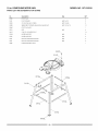
10 in. COMPOUND
MITER SAW
MODEL NO. 137.212310
PARTS LIST AND SCHEMATIC FOR STAND
QTY
Size
I.D.
Description
093B
FOOT PAD
0J4F
FLAT WASHER
q_8X] 6-2.5
0KE3
CR. RE. PAN HD. SCREW
M8* ] .25-35
3
0KRR
SERRATED TOOTHED HEXAGON FLANGE NUT
M8* ] .25 T=7.5
]9
20N0
FOOT PAD ASS'Y
22XY
LEG
#06
4
2A10
CAP HD. SQ.NECK BOLT
2F3Q
UPPER SUPPORT
#06
2
2F3R
UPPER SUPPORT
#06
2
2F3S
BOTTOM SUPPORT BRACKET
#06
2
2F3T
BOTTOM SUPPORT BRACKET
#06
2
2F8B
HARDWARE
4
3
]
]6
BAG ASS'Y
]
0 KE33
OJ4F3
2F3(
2F31_
2AI0_6
2F3S 2
2F3T_
22XY_
29
Your Home
For repair - in your home - of all major brand appliances,
lawn and garden equipment, or heating and cooling systems,
no matter who made it, no matter who sold it!
For the replacement parts, accessories and
owner's manuals that you need to do-it-yourself.
For Sears professional installation of home appliances
and items like garage door openers and water heaters.
1-800-4-MY-HOME
Call anytime,
®
(1-800-469-4663)
day or night (U.S.A. and Canada)
www.sears.oom
www.sears.oa
Our Home
For repair of carry-in items like vacuums, lawn equipment,
and electronics, call or go on-line for the location of your nearest
Sears Parts & Repair Center.
1-800-488-1222
Call anytime,
day or night (U.S.A. only)
www.sears.com
To purchase a protection agreement (U.S.A.)
or maintenance agreement (Canada) on a product serviced by Sears:
1-800-827-6655
Para pedir servicio
a domicilio,
(U.S.A.)
1-800-361-6665
de reparaci6n
y para ordenar
1-888-SU-HOGAR
Au Canada pour service
Trademark
TM
/
TM
Trademark
M
/s
Service
®
Mark of Sears
en fran£ais:
1-800-LE-FOYER
piezas:
M°
(1-800-533-6937)
www.sears.ca
(1-888-784-6427)
® Registered
(Canada)
Brands,
LLC
M
® Marca Registrada /
Marea de Fglbriea / s Marea de Servicio de Sears Brands, LLC
MD
MeMarque de commerce /
Marque depos6e de Sears Brands, LLC
© Sears Brands, LLC