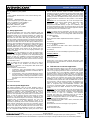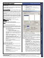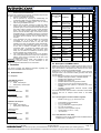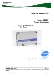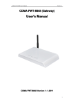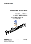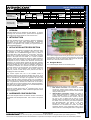
1
C-GPS Overview and Usage
APN Content Level
Software
Compatibility*
FW:
BASIC
6.61
9
INTERMEDIATE
Open AT®
4.11
SDK:
Plug-Ins:
M2mpower
* refer to software compatibility matrix section for more detail
Plug & Play:
M1306B
Quik (CDMA):
Q2438F
Q2400A
Wireless CPU
Quik (GSM):
GR64
Compatibility
Q24 Classic
Wireless Microprocessor
WMP100
Confidentiality
ADVANCED
M2106B
Q2438R
Q2406A
GS64
Q24 Plus
WMP150
TCP/IP
9
C-GPS
Internet
9
Bluetooth
MQTT
9
M2MC
CM52
Q2406B
Q2686H
Q24 Extended
9
Public
Compiler
Used:
RTE:
Q2426B
Q2687H
Q24 Auto
ADS
GCC
9
9
Private
Reference Hardware
Reference Software
Yes
Yes
Q2501B
9
1 VERSION
NOT E
WM_DEV_C-GPS_APN_001-001
Date:
30th November 2006
Wavecom Support Consultant
APP LICATION
Author:
Application Notes may be updated over their lifetime. To ensure
you design with the correct version, please check the application
notes page in the support section for www.wavecom.com.
This APN (Application Note) is provided to Wavecom distributors
and clients to aid more rapid development of embedded
applications using the Wavecom portfolio of cellular solutions. To
request a new application note, contact your regional Wavecom
Product Marketing Manager.
3 APPLICATION NOTE DESCRIPTION
®
Wavecom provides sample Open AT applications which can be
used to provide guidelines to create customized application based
on the requirements.
4 HARDWARE CONFIGURATION
The C-GPS Daughter board is connected to the J201 connector of
the wireless CPU development board. This is shown in the picture
below:
The C-GPS Daughter board has the following layout:
NOT E
4.1 Daughter Board
APPLICATION
The C-GPS chipset uses one of the available UART to
send/receive data from the Wavecom Wireless CPU. Hence, to be
able to receive the C-GPS data from the C-GPS chipset, FCM flow
®
must be subscribed by the Open AT application. As one of the
UART is internally used by the GPS chipset, it is not possible to
use this UART for any external application (like Terminal Emulator,
TMT or Hyperterminal). However, the UART which is not used by
GPS chipset can be used to interface with an external application.
This UART can be used to send/receive AT commands/responses
and also send the NMEA sentences.
The C-GPS Daughter board hence gets access to all the pins that
are provided on the J201 connector. Using these pins, the C-GPS
Daughter board is able to send/receive data to/from the Wavecom
Wireless CPU and hence able to interact with it.
The Daughter Board has the following main components:
1. GPS Antenna Connector: This connector is used to
connect the external GPS antenna with the C-GPS
chipset. Please note that the connection should be made
using an active antenna.
2. UART1/UART2 configuration switch: This switch is
used to select whether UART1 or UART2 is used by the
C-GPS Daughter board to communicate with the
Wireless CPU. If the switch is set to “UART1”, then the
Rx and Tx pins of UART2 will be used by C-GPS
Daughter board to send/receive the GPS data. Hence,
this UART cannot be used by the external application
(like TE/Hyperterminal). The “UART1” in this case,
becomes the debug UART and can be used to
send/receive AT commands and receive the NMEA
messages. Similarly, if the configuration switch is set to
UART2, then the C-GPS Daughter board is configured to
© 2006
All rights reserved
Page: 1 / 7
This document is the sole and exclusive property of WAVECOM. Not to be distributed or divulged without prior written agreement.
Ce document est la propriété exclusive de WAVECOM. Il ne peut être communiqué ou divulgué à des tiers sans son autorisation préalable.
Template: WM ACM F 007 level002
The acronym C-GPS stands for Companion GPS. Wavecom offers
its customers to ease the integration process of the GPS
functionalities with its GSM/GPRS Wireless CPU’s by offering a
®
ready-made library within the Open AT environment. This library
allows driving a Companion GPS chipset. In this release, the GPS
solution is the Opus One from eRide, Inc. In order to facilitate
evaluation, testing and development, Wavecom makes available a
development kit which includes a C-GPS Daughter board. This
development kit can be ordered from Wavecom and Wavecom
distributors. The C-GPS chipset receives the GPS data, performs
the preliminary processing on the data and forwards the data to the
®
Wavecom Wireless CPU. The Open AT application executed on
the Wavecom Wireless CPU receives this data and performs
processing based on the received data. The application need not
take care for low level interfacing with the GPS chipset as
Wavecom provides C-GPS library which performs the task of
managing the lower level details.
APPLICATION
NOT E
2 INTRODUCTION
C-GPS Overview and Usage
WM_DEV_C-GPS_APN_001-001
In addition to the above interface characteristics of the C-GPS
board, the C-GPS chipset requires the following signals to be
driven:
•
NRST: This input signal is used to reset the C-GPS
Daughter board.
•
GPS_ENABLE: This signal is used to enable the
acquisition of GPS NMEA sentences by the GPS
Daughter board.
•
TCXO_ENABLE: This signal is used to enable the
temperature compensated crystal oscillator.
Warning: DC voltage (VBATT) is always present on the “RF”
connector in order to power supply an antenna with LNA.
References: For further reference on the details of working of
Daughter board, please refer to C-GPS Development kit
User Guide (document [2]).
4.2 Configuration on Wavecom Motherboard
The motherboard of the Wavecom Wireless CPU which is
connected to the C-GPS Daughter board should also be configured
for proper working of the C-GPS Daughter board. The following
image depicts the wireless CPU motherboard which can be
connected to the C-GPS Daughter board.
NOT E
APP LICATION
1.
2.
3
4.
NRST
GPS_ENABLE
TCXO_ENABLE
LED
GPIO
providing
signal
GPIO19
GPIO 22
GPIO 23
GPIO 20
the
4.2.1 Configuration of Motherboard
The motherboard should be configured by providing the correct
switch position for “EN1/GPIO19” switch and “EN2/GPIO1” switch.
In case the user is planning to use UART1 for C-GPS, the
“EN1/GPIO19” switch must be set to select GPIO19. Also,
“EN2/GPIO1” switch must be set to EN2 to enable UART2 for the
PC.
In case the user is planning to use UART2 for C-GPS, the
“EN2/GPIO1” switch must be set to select GPIO1. Also,
“EN1/GPIO19” switch must be set to EN1 to enable UART1 for the
PC.
In addition to these configurations, the ON/OFF switch must be set
to ON and the Boot switch must be set to OFF.
5 C-GPS Open AT® Applications
®
Wavecom provides sample Open AT
applications which
®
demonstrate how Open AT applications can be created which can
be used to interface with the C-GPS Daughter board.
The following samples are provided by Wavecom:
1. Query Application
2. Interval Update Application
3. TCP Internet Connection Application
Important Note:
®
RTE mode is available with restrictions; see the Open AT SDK
Customer Release Note.
NOT E
Signal to be connected
APPLICATION
The C-GPS Daughter board should be connected to the J201
connector on the Wavecom Wireless CPU. In case, the user is
planning to use UART1 for C-GPS, then UART1/UART2
configuration switch must be set to UART2. Selection of incorrect
switch position might lead to non-working of the C-GPS Daughter
board. The C-GPS Daughter board has the following serial
communication parameters:
Baud Rate: 57600 bps
•
Character Framing: 8 Data bits, 1 stop bit and Odd
•
Parity.
•
Flow control: No flow control
®
These parameters need to be set by the Open AT application
which is interacting with the C-GPS Daughter board.
S.No.
NOT E
4.1.1 Configuration of Daughter Board
C-GPS Daughter board requires the NRST, GPS_ENABLE and
®
TCXO_ENABLE to be driven by the Open AT application. These
pins are connected with the following GPIOs on the Motherboard:
APPLICATION
NOTE: The GPS FIX LED is internally connected to GPIO20
of the Wireless CPU.
UART2/
GPIO1
switch
UART1/
GPIO19
switch
RTE mode may work with C-GPS if the baud rate is 460800 for the
UART used with the PC.
®
In Open AT SDK v4.11 in RTE mode you have to set the
RTE_PRODUCT_TYPE definition in "gpioconfig.h" (header file
used in the samples) to select your target.
The following statements should be added to be able to execute
the application correctly in RTE mode.
-> When Q2686 Wireless CPU is used, add the following lines of
code:
/***********/
/*Constants*/
/***********/
#if defined ( __REMOTETASKS__ )
/* Define the product type only for RTE mode */
/* ADL_IO_PRODUCT_TYPE_Q2686 or
ADL_IO_PRODUCT_TYPE_Q2687 */
© 2006
All rights reserved
Page: 2 / 7
This document is the sole and exclusive property of WAVECOM. Not to be distributed or divulged without prior written agreement.
Ce document est la propriété exclusive de WAVECOM. Il ne peut être communiqué ou divulgué à des tiers sans son autorisation préalable.
Template: WM ACM F 007 level002
3.
use UART1 for communicating with the Wireless CPU
(by using the Tx and Rx pins internally). Hence, UART1
cannot be used for any external application (like TE or
Hyperterminal). In this case, UART2 becomes the Debug
UART and Hyperterminal/TE can be connected to
UART2 to receive the Debug Traces and GPS data.
GPS Fix LED: A LED has been provided on the C-GPS
Daughter board. This LED indicates whether GPS fix has
been achieved or not. The behaviour of this LED is as
follows.
•
If GPS fix has not been achieved, the LED
keeps on glowing.
•
As soon as GPS fix is achieved, the LED
starts blinking. The LED blink frequency is the
same as the one with which the NMEA frames
are sent to the external application.
•
If GPS fix is lost, then again, the LED stops
blinking and keeps on glowing.
C-GPS Overview and Usage
NOTE: To retrieve the PVT information, the user has to send a
configuration SMS to the Wireless CPU where the Query
Application is in execution. The Configuration SMS should have
the following format:
INFO:<Password>:<Phonenumber>
1. <Password>: This is the Password which is configured
using AT+PASSWORD command. The default value of
the password is “CGPS”.
2. <Phonenumber>: This is the optional field which conveys
the phone number to which the PVT information is sent.
If the phone number is missing, the information is sent to
the number from which the configuration SMS has been
received.
For instance,
INFO:CGPS:994587883
5.2 Interval Update Application
This sample application uses the C-GPS Daughter board to
receive the GPS information. The user can send an SMS (called
the configuration SMS) to the Wavecom Wireless CPU where the
application is executing. The configuration SMS is used to
configure the sample to send the PVT information after a fixed
interval of time repeatedly using either SMS or TCP socket as a
bearer. It must be noted that the user must specify the correct
password in the configuration SMS (which is configured on the
Wireless CPU where the sample is in execution). The password is
configured using AT+PASSWORD command. The user also
specifies the bearer to be used (SMS/TCP socket i.e. IP
connection) to repeatedly send the PVT information along with the
update interval (interval after which the PVT information will be
sent). In case, TCP socket is used to send the PVT information,
the user must specify the IP address and Port of the server which
will be used by the sample application to connect to. In addition to
this, the configuration SMS must also specify the Access Point
For Instance,
INFO:CGPS:SMS:994598883:30
•
IP Bearer
INFO:<Password>:IP:<IPAddr>:<Port>:<APN>,<Username>,<Pas
sword>:<Optional Interval>
For Instance,
INFO:CGPS:IP:10.15.22.33:80:testapn,myusername,mypwd:20
Stopping a Bearer:
INFO:<Password>:STOP
For Instance,
INFO:CGPS:STOP
APP LICATION
NOT E
NOTE: To retrieve the PVT information, the user has to send a
configuration SMS to the Wireless CPU where the Interval Update
Application is in execution. The Configuration SMS should have
the following format:
•
SMS bearer
INFO:<Password>:SMS:<OptionalPhonenumber>:<Optional
Interval>
APPLICATION
This sample application uses the C-GPS Daughter board and
receives the GPS data from it. The user can send an SMS (called
configuration SMS) to the Wavecom Wireless CPU where the
application is in execution to get the PVT (Position, Velocity and
Time) data. The PVT data is sent using an SMS to the user. The
user has to specify a password (which is configured at the Wireless
CPU where the Query Application Sample is running) to be able to
receive the PVT data. The user can also specify a different phone
number to which the SMS containing the PVT data would be sent.
The application can also be configured to display the NMEA
sentences received from the C-GPS Daughter board (either in
formatted NMEA format or in RAW format) using a customer AT
command (AT+NMEA). These frames can be received over the
Debug UART. Hence, the user can use mapping software to get
the GPS coordinates.
References: For more information, as to how the sample works,
please refer to the Query Application sample description HTML
document. (This document is present in the /Samples/QueryApp
®
directory in Open AT installation) This document describes the
custom AT commands which can be used to configure various
parameters for the sample application and the format in which the
PVT information is sent.
Please refer to the Interval Update Sample Description HTML
document form more information on the above mentioned fields in
the configuration SMS.
5.3 TCP Internet Connection application
This sample application depicts a use case scenario in which the
user wants to send the NMEA frames to a TCP server socket
which is using mapping software for GPS to calculate the position
of the Wireless CPU. The application interfaces with C-GPS
Daughter board to receive the GPS information. A configuration
SMS is sent to the Wavecom Wireless CPU where the application
is in execution and configures the IP address, port, access point
name, access point username and access point password for
establishing a TCP socket. The configuration SMS also provides
the update interval (interval after which the NMEA data is sent to
the TCP server). Like the previous samples, this application too
requires the user to give a password in the configuration SMS
which is configured using AT+PASSWORD command. After
receiving the configuration SMS, the sample establishes a TCP
socket and sends the NMEA sentences over the established
socket.
References: For more information, as to how the sample works,
please refer to the TCP Internet Connection Sample Description
HTML document. This document is present in the /Samples/TCP
®
Server directory in Open AT installation). This document
describes the custom AT commands which can be used to
configure various parameters for the sample application.
NOTE: The configuration SMS that is to be sent to the Wireless
CPU should have the following format:
INFO:<Password>:IP:<IPAddr>:<Port>:<APN>,<Username>,<Pas
sword>:<Optional Interval>
For Instance,
INFO:CGPS:IP:10.22.33.44:80:myapn,myun,mypwd:20
To stop the bearer use:
INFO:<Password>:STOP
© 2006
All rights reserved
Page: 3 / 7
This document is the sole and exclusive property of WAVECOM. Not to be distributed or divulged without prior written agreement.
Ce document est la propriété exclusive de WAVECOM. Il ne peut être communiqué ou divulgué à des tiers sans son autorisation préalable.
NOT E
5.1 Query Application
APPLICATION
-> When a Q2687 Wireless CPU is used, use the following code.
/*Constants*/
/***********/
#if defined ( __REMOTETASKS__ )
/* Define the product type only for RTE mode */
/* ADL_IO_PRODUCT_TYPE_Q2686 or
ADL_IO_PRODUCT_TYPE_Q2687 */
#define RTE_PRODUCT_TYPE
ADL_IO_PRODUCT_TYPE_Q2687
#endif
name, Access Point Username and Access Point Password to be
able to activate the PDP context for GPRS connection. This
application can also be configured to send the GPS frames (either
in formatted NMEA format or in RAW format) over the Debug
UART (using AT+NMEA command). Hence, the user has the
flexibility to receive the NMEA frames locally and hence can use
mapping software to calculate the GPS position of the Wireless
CPU.
References: For more information, as to how the sample works,
please refer to the Interval Update Sample Description HTML
document.
This
document
is
present
in
the
®
/Samples/IntervalUpdate directory in Open AT installation). This
document describes the custom AT commands which can be used
to configure various parameters for the sample application and the
format in which the PVT information is sent.
Template: WM ACM F 007 level002
#define RTE_PRODUCT_TYPE
ADL_IO_PRODUCT_TYPE_Q2686
#endif
NOT E
WM_DEV_C-GPS_APN_001-001
C-GPS Overview and Usage
12.
APPLICATION
NOT E
13.
5.4 Steps to Download the Samples
NOTE: UART2 or USB cannot be used to download the Open AT
application.
®
5.4.1 Downloading using XModem Protocol
The user can download the sample using the XModem protocol
using Hyperterminal (or a similar serial port utility which provides
XModem protocol to transfer information). Following steps should
be taken to download the sample
1. Connect UART1 with the PC which has the application
binary. The connection parameters for Hyperterminal (or
similar application should be):
a. Baud Rate: 115200 bauds/sec
b. Data bits: 8 data bits, no parity, 1 stop bit.
2. Set the BOOT switch on the Wavecom Wireless CPU
Motherboard to OFF. The ON/OFF switch should be set
to ON. Make sure that the CGPS Daughter board is not
connected.
3. Execute the command AT+WDWL. The XModem NACK
characters (‘$”) would start to appear.
4. Transfer
the
sample
binary
application
(compilerused_workspacename_H.wpb.dwl
or
compilerused_workspacename_H.dwl).
NOTE:
The
literal compilerused can have the values “ads” or “gcc”
depending on the compiler which is used to compile the
application.
5. After the download is complete, execute AT+CFUN=1
command to reset the Wireless CPU.
®
6. Execute AT+WOPEN=1 command to start the Open AT
sample application.
5.4.2 Downloading using DwlWin
Wavecom provides a utility called DwlWin which can be used to
download the sample applications.
The steps to download the sample are:
1. Connect to UART1 (115200 bauds, 8 data bits, no parity,
1 stop bit).
2. On the Wavecom Wireless CPU Development Board set
the boot switch to ON.
3. Configure DWLWIN as shown below.
4. Make sure the C-GPS Daughter board is not connected.
5. Select the sample application having the extension .wpb
at the end.
6. Start the download.
7. Once completed, switch the boot back to OFF.
8. Connect the C-GPS Daughter board.
5.5 Steps to Execute the Samples
®
To start the Open AT application, the command AT+WOPEN=1
needs to be given. The user must configure the switch positions on
the Daughter board (to select the UART to be used for C-GPS) and
the switch positions on the Wavecom Wireless CPU motherboard
as described earlier in this document.
All the samples subscribe to a set of custom AT commands which
define the way in which the sample behaves. The set of AT
commands along with their description are:
1. AT+NMEA: This command specifies if the NMEA frames
(either in formatted or in RAW format) are to be received
over the Debug UART.
2. AT+PASSWORD: This command specifies the
password to be used in the configuration SMS to
authenticate a valid user. The password is stored in flash
memory. The default value of the password is “CGPS”
and the password is case sensitive.
3. AT+CGPS: This command provides information as to
which UART is to be used for C-GPS Daughter board.
The UART which is left automatically becomes the
Debug UART. After giving this command, the sample
starts executing.
4. AT+CONFIG: If a value of 1 is specified as an argument
to this command, then the values for AT+NMEA and
AT+CGPS are saved in flash memory. Hence, if the
Wireless CPU resets, the sample application
automatically starts executing (without user intervention)
using the previously saved parameters for +NMEA and
+CGPS commands. Please note that to disable this
© 2006
All rights reserved
Page: 4 / 7
This document is the sole and exclusive property of WAVECOM. Not to be distributed or divulged without prior written agreement.
Ce document est la propriété exclusive de WAVECOM. Il ne peut être communiqué ou divulgué à des tiers sans son autorisation préalable.
NOT E
POINTS TO REMEMBER:
1. The difference between the TCP Internet Connection sample
and the Interval Update sample is that the TCP Internet
Connection sample sends the data in exact NMEA format over the
established TCP socket. The Interval Update sample, on the other
hand, sends data in a particular format (used for sending PVT
information).
Another difference between the TCP Internet Connection sample
and the Interval Update sample is that the TCP Server sample
sends NMEA sentences only over TCP socket after a specified
update interval whereas the Interval Update sample can be used to
send PVT data over TCP socket or SMS after a specified update
interval.
2. All the sample applications use the following serial port
communication parameters for the Debug UART:
Speed: 115200 Bauds/second.
Character Framing: 8 data bits, 1 stop bits, parity ignored.
Flow control: No flow control.
10.
11.
APPLICATION
For more information on the meanings of various fields of the
configuration SMS, please refer to the TCP Internet Connection
Sample Description HTML document.
Set UART1/UART2 switch on C-GPS Daughter board to
UART2.
Push the hardware reset.
®
If needed start the Open AT application using
AT+WOPEN=1.
Connect to the port UART2 (115200 bauds, 8 data bits,
no parity, 1 stop bit).
NMEA should be sent to the UART2.
APP LICATION
9.
Template: WM ACM F 007 level002
For Instance,
INFO:CGPS:STOP
NOT E
WM_DEV_C-GPS_APN_001-001
C-GPS Overview and Usage
WM_DEV_C-GPS_APN_001-001
This section provides vital statistical information regarding the
performance and NMEA Frame description.
6.1 Performances
6.1.1 Footprint
C-GPS ARM lib footprint
Memory Footprint:
•
ROM : 245397 Bytes
•
RAM (static): 106293 Bytes
C-GPS CPU load:
Normal mode
C-GPS
C-GPS with NMEA frame
48%
49%
Boost activated
C-GPS
C-GPS with NMEA frame
40%
45%
NOT E
®
Velocity
Accuracy
Static mode
First fix only
TTFF Hot Start
TTFF
Warm
Start
TTFF
Cold Clear
Start
conditions
Clear
conditions
Update Rate
-130 dBm
Sky
Sky
3,7 m CEP
6,8 m CEP
6,1 m CEP
13,9
CEP
m
0,1 m/s
Typ
0 m/s
Typ
3,5 s
Typ
Mean
30s
Typ
Mean
38 s
Typ
95% percentile 45 s
Typ
Continuous
fixes
1 Hz
Typ
1,1 dB
Typ
Continuous
fixes
Mean
Static mode
APP LICATION
-130
dBm(outdoor) In 50% percentile
dynamic mode
-130
dBm(outdoor) In 95% percentile
dynamic mode
-140 dBm In
50% percentile
dynamic mode
-145 dBm In
50% percentile
dynamic mode
Accuracy
Value
Desensitizatio
1 GSM burst Continuous
n due to GSM
over 8 slots
fixes
Tx bursts
NOT E
Notes
APPLICATION
Open AT SDK
Conditions
v 4.11
6.2 Description of NMEA Frames
NMEA 0183 standard defines the NMEA sentences and for each of
these sentences the first word, called a data type defines how the
rest of the sentence is interpreted. Each data has its own unique
interpretation, as defined by the NMEA standard.
Sentences vary in the information they contain. Some sentences
will repeat some of the information already provided, while others
provide new data.
Type of NMEA tags included in the C-GPS sample application are:
•
$GPGLL Geographic Position, Latitude/Longitude
•
$GPGSV GPS Satellites in View Data
•
$GPZDA UTC Date & Time
•
$GPGGA Global Positioning System Fix Data
•
$GPVTG Course over ground and ground speed
•
$GPGSA GPS DoP (Dilution of Precision) and Active
Satellites
•
$GPRMC Recommended Minimum Specific GNSS
GPS/TRANSIT Data
This section describes what information is included in which NMEA
sentence and how to interpret various fields in the NMEA
sentence:
NOT E
6 Annexes
6.1.2 GPS
APPLICATION
feature, the user should give AT+CONFIG=0 command
and then reset the Wireless CPU.
Using the above mentioned commands, the following steps should
be used to execute the sample applications:
1. Execute AT+WOPEN=1 command.
2. Set the password (if required) for authenticating the
configuration SMS using AT+PASSWORD command.
3. Set the availability of NMEA frames over the Debug
UART using AT+NMEA command.
4. Execute the AT+CGPS command to select the UART
which must be used by the C-GPS Daughter board. The
parameter given for the command must be coherent with
the switch position provided on the C-GPS Daughter
board. The C-GPS sample application will start at this
point of time and will take roughly 15 seconds to receive
the NMEA frames. If AT+NMEA command is configured
to display the NMEA frames over the Debug UART, then
the frames will be received over the UART after 15
seconds.
5. If the parameters set using AT+NMEA and AT+CGPS
commands are to be saved, then the command
AT+CONFIG=1 should be issued. In this case, after
Wireless CPU reset, the application would automatically
start using the saved parameters and there is no need
for the user to execute AT+NMEA and AT+CGPS
commands again. To prevent the Wireless CPU from
using the same configuration again and again (after
reset), the command AT+CONFIG=0 should be given
and the Wireless CPU should be reset.
6. The configuration SMS should be sent to the Wireless
CPU. If the password and the format of the configuration
SMS is correct, the PVT information will be sent to the
provided phone number.
Reference: Please refer to the HTML help available in the
corresponding samples directory for more information on the
format of configuration SMS and the PVT information.
6.2.1 GLL (Geographic Position Latitude Longitude)
C-GPS GCC lib footprint
Memory Footprint:
•
ROM : 304371 Bytes
•
RAM (static): 29263 Bytes
C-GPS CPU load:
Normal mode
C-GPS
C-GPS with NMEA frame
47%
53%
Boost activated
C-GPS
C-GPS with NMEA frame
40%
45%
•
•
•
•
•
•
•
llll.ll Destination waypoint latitude
E N or S (for latitude)
yyyyy.yy Destination waypoint longitude
F E or W (for longitude)
hhmmss.ss UTC of position fix (time)
A Data Status (A = OK, V = Void)
*hh Checksum
6.2.2 GSV (Satellites in View Data)
$GPGSV,A,B,C,D1,E1,Az1,SNR1,D2,E2,Az2,SNR2,D3,E3,A
z3,SNR3,D4,E4, Az4,SNR4*hh
© 2006
All rights reserved
Page: 5 / 7
This document is the sole and exclusive property of WAVECOM. Not to be distributed or divulged without prior written agreement.
Ce document est la propriété exclusive de WAVECOM. Il ne peut être communiqué ou divulgué à des tiers sans son autorisation préalable.
Template: WM ACM F 007 level002
$GPGLL,llll.ll,E,yyyyy.yy,F,hhmmss.ss,A*hh
C-GPS Overview and Usage
$GPZDA,hhmmss.ss,dd,mm,yyyy,xx,yy,*hh
•
•
•
•
•
•
•
•
•
•
•
•
•
•
•
•
•
•
•
hhmmss.ss UTC of position fix (time)
A Data Status (A = OK, V = Void)
llll.ll Destination waypoint latitude
E N or S (for latitude)
yyyyy.yy Destination waypoint longitude
F E or W (for longitude)
SOG Speed Over Ground (knots)
COG Course Over Ground (°)
Ddmmyy Date Stamp coordinated
MV Magnetic Variation (°)
F East or West Magnetic Variation Direction
M Mode indicator
A= Autonomous
D= Differential
E= Dead Reckoning,
N= None
*hh Checksum
hhmmss.ss UTC of position fix (time)
dd Day
mm Month
yyyy Year
xx Local zone hours (-13 to 13)
yy Local zone minutes (00 to 59)
*hh Checksum
6.2.4 GGA (Global Positioning System Fix Data)
$GPGGA,hhmmss.ss,llll.ll,E,yyyyy.yy,F,A,bb,x.x,y.y,M,z.
z,M,s.s,####,*hh
•
•
•
•
•
•
•
•
•
•
•
•
•
hhmmss.ss UTC of position fix (time)
llll.ll Destination waypoint latitude
E N or S (for latitude)
yyyyy.yy Destination waypoint longitude
F E or W (for longitude)
A Fix quality:
0 = Invalid
1 = GPS fix (SPS)
2 = DGPS fix
3 = PPS fix
4 = Real Time Kinematic
5 = Float RTK
6 = Estimated (dead reckoning)
7 = Manual input mode
8 = Simulation mode
bb Number of satellites in use
x.x Horizontal error (precision)
y.y,M Antenna height in meters
z.z,M Height of geoid (mean sea level) in meters
s.s Time in seconds since last update
#### DGPS station ID
*hh Checksum
6.2.5 VTG (Course over Ground and Ground Speed)
•
7 PACKAGE DELIVERABLES
This application note is delivered as a single compressed zip
archive as follows:
Filename
WM_DEV_C-GPS_APN_001-001.zip
•
COG,T Course over Ground (T = true)
COG,M Course over Ground (M = magnetic)
SOG,N Speed over Ground (N= knots)
SOG,K Speed over Ground (K = km/h)
M Mode indicator
A= Autonomous
D= Differential
E= Estimated (Dead Reckoning)
N= None
*hh Checksum
Description
Application Note
7.1 DOCUMENTATION
-
This application note
eRide APIs Technical Manual
C-GPS Development kit User Guide
Samples description document
8 RELATED DOCUMENTS
[1]
Filename
eTM-GCLAPI-CoreLib_API.pdf
[2]
WM_DEV_C-GPS_UGD_001
[3]
[4]
MiniRide Datasheet.pdf
Prelude1 RF Receiver
Datasheet.pdf
Opus1, GPS Receiver
Datasheet.pdf
MG-001ApprovalSheet.pdf
$GPVTG,COG,T,COG,M,SOG,N,SOG,K,A*hh
•
•
•
•
•
[5]
[6]
Description
eRide APIs Technical
Manual
C-GPS Development
kit User Guide
MiniRide Datasheet
Prelude1 Datasheet
Opus1 Datasheet
Specification for
approval
6.2.6 GSA (GNSS DOP – Dilution of Precision and active
satellites)
$GPGSA,OM,NM,D1-D12,PDOP, HDOP, VDOP*hh
•
•
•
APP LICATION
$GPRMC,hhmmss.ss,A,llll.ll,E,yyyyy.yy,F,SOG,
COG,ddmmyy,MV,F,M*hh
6.2.3 ZDA (Date and Time)
NOT E
6.2.7 RMC (Recommended Minimum Specific Data)
APPLICATION
•
•
•
•
•
•
NM Navigation Mode
1 : Fix not available
2 : 2D
3 : 3D
D1-D12 Satellite Vehicles Used in Position Fix
PDOP Position Dilution of Precision (PDOP)
HDOP Horizontal Dilution of Precision (HDOP)
VDOP Vertical Dilution of Precision (VDOP)
*hh Checksum
NOT E
•
•
APPLICATION
•
•
•
•
•
A Number of messages required to hold data on all SVs
in view
B Message number
C Total number of satellites in view
D1-D4 Satellite PRN number
E1-E4 Elevation in degrees (90 maximum)
Az1-Az4 Azimuth (measured in degrees from True north,
000 to 359
SNR1-SNR4 Signal-to-noise ratio (the higher the number
the better the signal)
*hh Checksum
OM Operation Mode
M : Manual forced to operate in 2D or 3D
A : Automatic 2D/3D
© 2006
All rights reserved
Page: 6 / 7
This document is the sole and exclusive property of WAVECOM. Not to be distributed or divulged without prior written agreement.
Ce document est la propriété exclusive de WAVECOM. Il ne peut être communiqué ou divulgué à des tiers sans son autorisation préalable.
Template: WM ACM F 007 level002
•
NOT E
WM_DEV_C-GPS_APN_001-001
C-GPS Overview and Usage
9 SOFTWARE COMPATIBILITY MATRIX
List all current software configurations and compatibility with this
application note.
®
®
Open AT SDK
4.11
Open AT Plug-Ins
WIP v1.10.02
10 SUPPORT
For direct clients: contact your Wavecom FAE
For distributor clients: contact your distributor FAE
For distributors: contact your Wavecom FAE
APP LICATION
®
Open AT FW
6.61
NOT E
WM_DEV_C-GPS_APN_001-001
11 DOCUMENT HISTORY
History
Creation
Author
Wavecom Support Consultant
12 LEGAL NOTICE
LICENCE RIGHTS
Wavecom Asia Pacific Ltd hereby grant licence to users of their Open AT (TM) development environment to use the source code in
this electronic file for the sole use of developing GSM, GSM/GPRS or GSM/GPRS/GPS cellular applications compatible with
Wavecom products. The source code may be modified by any Open AT (TM) developer providing the application is not intended to be
malicious or detrimental to cellular operators or consumers of the application in any way. The licence also grants permission to copy
and distribute this source code so long as this licence header is maintained in all source code files. You hereby undertake to use the
Software for your interim development purposes only and under no circumstances shall you use the Software for commercial
purposes. For the avoidance of doubt, the Software may not be sold for a fee on diskette or CD-ROM, either alone or as part of a
collection with other products without prior written consent from Wavecom.
DISCLAIMER OF WARRANTY
This Software is provided free of charge on an 'as is' basis. No warranty whether expressed or implied is given by Wavecom in relation
to the Software of the uses to which it may be put by you, the user, or its performance or merchantability, fitness or suitability for any
particular purpose or conditions; and/or that the use of the Software and all documentation relating thereto (the “Documentation”) by
the Licensee will not infringe any third party copyright or other intellectual property rights. Wavecom shall furthermore be under no
obligation to provide support of any nature for the Software and the Documentation.
LIMIT OF LIABILITY
In no event shall Wavecom be liable for any loss or damages whatsoever or howsoever caused arising directly or indirectly in
connection with this licence, the Software, its use or otherwise irrespective of whether Wavecom has had advance notice of the
possibility of such damages or not by your use of the Software. Notwithstanding the generality of the foregoing, Wavecom expressly
excludes liability for indirect, special, incidental or consequential loss or damage which may arise in respect of the Software or its use,
or in respect of other equipment or property, or for loss of profit, business, revenue, goodwill or anticipated savings.
NOT E
Date
23/11/2006
APPLICATION
Level
001
Template: WM ACM F 007 level002
APPLICATION
NOT E
INTELLECTUAL PROPERTY
For the avoidance of doubt, no right, title or interest in any intellectual property right in respect of the Software shall pass to you. Any
and all intellectual property rights in respect of the Software and Documentation shall at all times remain the sole and exclusive
property of Wavecom. The licence grant shall not include Intellectual Property not wholly owned by Wavecom and the customer shall
exercise due diligence to ensure that the use of the information in this document does not infringe any patents in the country of origin.
© 2006
All rights reserved
Page: 7 / 7
This document is the sole and exclusive property of WAVECOM. Not to be distributed or divulged without prior written agreement.
Ce document est la propriété exclusive de WAVECOM. Il ne peut être communiqué ou divulgué à des tiers sans son autorisation préalable.