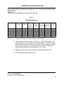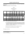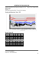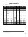
1
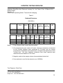
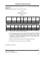
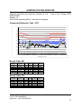
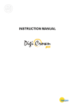
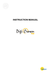
ShenZhen Aoni Electronic Industry Co., Ltd.
Application
For
Certification
(FCC ID: Z63-AONI80601)
Bluetooth headset
Model: BT806, AF52
2.4GHz Transceiver
Report No.: 130312018SZN-001
We hereby certify that the sample of the above item is considered to comply with the
requirements of FCC Part 15, Subpart C for Intentional Radiator,
mention 47 CFR [10-1-12]
Prepared and Checked by:
Approved by:
Digitally signed
by Billy Li
Location: Intertek
Testing Services
Sign on file
Chris Chen
Engineer
Billy Li
Supervisor
Date: 15 March 2013
•
The test results reported in this test report shall refer only to the sample actually tested and shall not refer or be deemed to refer to bulk from which such a sample
may be said to have been obtained.
•
This report is for the exclusive use of Intertek's Client and is provided pursuant to the agreement between Intertek and its Client. Intertek's responsibility and liability
are limited to the terms and conditions of the agreement. Intertek assumes no liability to any party, other than to the Client in accordance with the agreement, for
•
•
any loss, expense or damage occasioned by the use of this report. Only the Client is authorized to copy or distribute this report. Any use of the Intertek name or
one of its marks for the sale or advertisement of the tested material, product or service must first be approved in writing by Intertek. The observations and test
results referenced from this report are relevant only to the sample tested. This report by itself does not imply that the material, product, or service is or has ever
been under an Intertek certification program.
For Terms And Conditions of the services, it can be provided upon request.
The evaluation data of the report will be kept for 3 years from the date of issuance.
TRF No.: FCC 15C_TX_b
Intertek Testing Services Shenzhen Ltd. Kejiyuan Branch
6F, D Block, Huahan Building, Langshan Road, Nanshan District, Shenzhen, P. R. China
Tel: (86 755) 8601 6288
Fax: (86 755) 8601 6751 Website: www.china.intertek-etlsemko.com
INTERTEK TESTING SERVICES
LIST OF EXHIBITS
INTRODUCTION
EXHIBIT 1:
General Description
EXHIBIT 2:
System Test Configuration
EXHIBIT 3:
Emission Results
EXHIBIT 4:
Equipment Photographs
EXHIBIT 5:
Product Labelling
EXHIBIT 6:
Technical Specifications
EXHIBIT 7:
Instruction Manual
EXHIBIT 8:
Miscellaneous Information
EXHIBIT 9:
Confidentiality Request
EXHIBIT 10:
Test Equipment List
TRF No.: FCC 15C_TX_b
FCC ID: Z63-AONI80601
Report No.: 130312018SZN-001
i
INTERTEK TESTING SERVICES
MEASUREMENT/TECHNICAL REPORT
ShenZhen Aoni Electronic Industry Co., Ltd.
Model: BT806, AF52
FCC ID: Z63-AONI80601
This report concerns (check one:)
Original Grant X
Class II Change
Equipment Type: DXX - Part 15 Low Power Communication Device Transmitter
Deferred grant requested per 47 CFR 0.457(d)(1)(ii)?
Yes
No
X
If yes, defer until:
date
Company Name agrees to notify the Commission by:
date
of the intended date of announcement of the product so that the grant can be issued on that
date.
Transition Rules Request per 15.37?
Yes
No
X
If no, assumed Part 15, Subpart C for intentional radiator − the new 47 CFR [10-1-12
Edition] provision.
Report prepared by:
Billy Li
Intertek Testing Services Shenzhen Ltd.
Kejiyuan Branch
6F, Block D, Huahan Building, Langshan Road,
Nanshan District, Shenzhen, P. R. China
Phone: (86 755) 8601 0645
Fax:
(86 755) 8601 6751
TRF No.: FCC 15C_TX_b
FCC ID: Z63-AONI80601
Report No.: 130312018SZN-001
ii
INTERTEK TESTING SERVICES
Table of Contents
1.0 General Description ............................................................................................ 2
1.1 Product Description ............................................................................................ 2
1.2 Related Submittal(s) Grants ............................................................................... 2
1.3 Test Methodology............................................................................................... 2
1.4 Test Facility ........................................................................................................ 2
2.0 System Test Configuration ................................................................................. 4
2.1 Justification ........................................................................................................ 4
2.2 EUT Exercising Software .................................................................................... 4
2.3 Special Accessories ........................................................................................... 4
2.4 Equipment Modification ...................................................................................... 5
2.5 Measurement Uncertainty .................................................................................. 5
2.6 Support Equipment List and Description ............................................................. 5
3.0 Emission Results ................................................................................................ 7
3.1Radiated Test Results…………………………………………………………………. 8
3.1.1 Field Strength Calculation ................................................................................ 8
3.1.2 Radiated Emission Configuration Photograph .................................................. 9
3.1.3 Radiated Emissions ......................................................................................... 9
3.1.4 Transmitter Spurious Emissions (Radiated)…………………………………….. 12
3.2 Conducted Emission at Mains Terminal…………………………………………… 16
3.2.1 Conducted Emissions Configuration Photograph………………………………..16
3.2.2 Conducted Emissions………………………………………………………………16
4.0 Equipment Photographs ................................................................................... 20
5.0 Product Labelling .............................................................................................. 22
6.0 Technical Specifications ................................................................................... 24
7.0 Instruction Manual ............................................................................................ 26
8.0 Miscellaneous Information ............................................................................... 28
8.1 Bandedge Plot ................................................................................................. 29
8.2 Discussion of Pulse Desensitizatio ................................................................... 31
8.3 Transmitter Duty Cycle Calculation ......................................................................32
8.4 Emissions Test Procedures .............................................................................. 33
9.0 Confidentiality Request ........................................................................................36
10.0 Test Equipment List ............................................................................................38
TRF No.: FCC 15C_TX_b
FCC ID: Z63-AONI80601
Report No.: 130312018SZN-001
iii
INTERTEK TESTING SERVICES
List of attached file
Exhibit type
Test Report
Test Setup Photo
Test Setup Photo
Test Report
Test Report
External Photo
Internal Photo
Block Diagram
Schematics
Operation Description
ID Label/Location
User Manual
Cover Letter
Cover Letter
File Description
Test Report
Radiated Emission
Conducted Emission
Bandedge Plot
20dB BW Plot
External Photo
Internal Photo
Block Diagram
Circuit Diagram
Technical Description
Label Artwork and Location
User Manual
Confidentiality Letter
Letter of Agency
Filename
report.pdf
radiated photos.pdf
conducted photos.pdf
bandedge.pdf
bw.pdf
external photos.pdf
internal photos.pdf
block.pdf
circuit.pdf
descri.pdf
label.pdf
manual.pdf
request.pdf
agency.pdf
TRF No.: FCC 15C_TX_b
FCC ID: Z63-AONI80601
Report No.: 130312018SZN-001
iv
INTERTEK TESTING SERVICES
EXHIBIT 1
GENERAL DESCRIPTION
TRF No.: FCC 15C_TX_b
FCC ID: Z63-AONI80601
Report No.: 130312018SZN-001
1
INTERTEK TESTING SERVICES
1.0
General Description
1.1
Product Description
The equipment under test (EUT) is a Bluetooth headset with Bluetooth
function. The EUT was powered by DC 3.7V Internal rechargeable battery
which can be charged by USB Port. For more detail information pls. refer to
the user manual.
Antenna Type: Integral antenna
Modulation Type: GFSK, π/4 –DQPSK and 8-DPSK
The Model: AF52 is the same as the Model: BT806 in hardware aspect, the
difference in model number serves as marketing strategy.
For electronic filing, the brief circuit description is saved with filename:
descri.pdf.
1.2
Related Submittal(s) Grants
This is an application for certification of a transceiver for the Bluetooth headset
which has Bluetooth function, and there is no corresponding unit for certification.
1.3
Test Methodology
Both AC mains line-conducted and radiated emission measurements were
performed according to the procedures in ANSI C63.4 (2009). Radiated
emission measurement was performed in Semi-anechoic chamber and
conducted emission measurement was performed in shield room. For radiated
emission measurement, preliminary scans were performed in the semianechoic chamber only to determine the worst case modes. All radiated tests
were performed at an antenna to EUT distance of 3 meters, unless stated
otherwise in the "Justification Section" of this Application. All other
measurements were made in accordance with the procedures in part 2 of
CFR 47.
1.4
Test Facility
The Semi-anechoic chamber and shielding room used to collect the radiated
data and conducted data are Intertek Testing Services Shenzhen Ltd.
Kejiyuan Branch and located at 6F, D Block, Huahan Building, Langshan
Road, Nanshan District, Shenzhen, P. R. China. This test facility and site
measurement data have been fully placed on file with the FCC(Registration
Number: 242492).
TRF No.: FCC 15C_TX_b
FCC ID: Z63-AONI80601
Report No.: 130312018SZN-001
2
INTERTEK TESTING SERVICES
EXHIBIT 2
SYSTEM TEST CONFIGURATION
TRF No.: FCC 15C_TX_b
FCC ID: Z63-AONI80601
Report No.: 130312018SZN-001
3
INTERTEK TESTING SERVICES
2.0
System Test Configuration
2.1
Justification
The system was configured for testing in a typical fashion (as a customer would
normally use it), and in the confines as outlined in ANSI C63.4 (2009).
The EUT was powered by a 3.7 VDC fully charged Li-ion rechargeable battery
charged by PC USB source and the PC was powered by an AC/DC Adapter
with AC 120V, 60Hz input during the test.
All packets DH1, DH3 & DH5 mode in modulation type GFSK, π/4 –DQPSK and
8-DPSK were tested, and only the worst data was reported in this report.
For maximizing emissions, the EUT was rotated through 360°, the antenna
height was varied from 1 meter to 4 meters above the ground plane, and the
antenna polarization was changed. This step by step procedure for maximizing
emissions led to the data reported in Exhibit 3.
The rear of unit shall be flushed with the rear of the table.
The equipment under test (EUT) was configured for testing in a typical fashion
(as a customer would normally use it). The EUT was placed on a turn table,
which enabled the engineer to maximize emissions through its placement in the
three orthogonal axes.
2.2
EUT Exercising Software
The EUT exercise program (provided by client) used during testing was
designed to exercise the various system components in a manner similar to a
typical use.
2.3
Special Accessories
N/A
TRF No.: FCC 15C_TX_b
FCC ID: Z63-AONI80601
Report No.: 130312018SZN-001
4
INTERTEK TESTING SERVICES
2.4
Equipment Modification
Any modifications installed previous to testing by ShenZhen Aoni Electronic
Industry Co., Ltd. will be incorporated in each production model sold / leased
in the United States.
2.5
No modifications were installed by Intertek Testing Services Shenzhen Ltd
Kejiyuan Branch.
Measurement Uncertainty
When determining the test conclusion, the Measurement Uncertainty of test has
been considered.
2.6
Support Equipment List and Description
Description
Manufacturer
Model No.
iPod
Apple
A1367
Laptop
Lenovo
T420
Aux Cable
Aoni
Unshielded, Length 155cm
USB Cable
Aoni
Unshielded, Length 85cm
TRF No.: FCC 15C_TX_b
FCC ID: Z63-AONI80601
Report No.: 130312018SZN-001
5
INTERTEK TESTING SERVICES
EXHIBIT 3
EMISSION RESULTS
TRF No.: FCC 15C_TX_b
FCC ID: Z63-AONI80601
Report No.: 130312018SZN-001
6
INTERTEK TESTING SERVICES
3.0
Emission Results
Data is included worst-case configuration (the configuration which resulted in the
highest emission levels). A sample calculation, configuration photographs and
data tables of the emissions are included.
TRF No.: FCC 15C_TX_b
FCC ID: Z63-AONI80601
Report No.: 130312018SZN-001
7
INTERTEK TESTING SERVICES
3.1
Radiated Test Results
A sample calculation, configuration photographs and data tables of the
emissions are included.
3.1.1 Field Strength Calculation
The field strength is calculated by adding the reading on the Spectrum Analyzer
to the factors associated with preamplifiers (if any), antennas, cables, pulse
desensitization and average factors (when specified limit is in average and
measurements are made with peak detectors). A sample calculation is
included below.
FS = RA + AF + CF - AG + PD + AV
Where
FS = Field Strength in dBµV/m
RA = Receiver Amplitude (including preamplifier) in dBµV
CF = Cable Attenuation Factor in dB
AF = Antenna Factor in dB
AG = Amplifier Gain in dB
PD = Pulse Desensitization in dB
AV = Average Factor in -dB
In the radiated emission table which follows, the reading shown on the data
table may reflect the preamplifier gain. An example of the calculations, where
the reading does not reflect the preamplifier gain, follows:
FS = RA + AF + CF - AG + PD + AV
Assume a receiver reading of 62.0 dBµV is obtained. The antenna factor of 7.4
dB and cable factor of 1.6 dB is added. The amplifier gain of 29 dB is
subtracted. The pulse desensitization factor of the spectrum analyzer was 0
dB, and the resultant average factor was -10 dB. The net field strength for
comparison to the appropriate emission limit is 32 dBµV/m. This value in dBµV/m
was converted to its corresponding level in µV/m.
RA = 62.0 dBµV
AF = 7.4 dB
CF = 1.6 dB
AG = 29.0 dB
PD = 0 dB
AV = -10 dB
FS = 62 + 7.4 + 1.6 - 29 + 0 + (-10) = 32 dBµV/m
Level in µV/m = Common Antilogarithm [(32 dBµV/m)/20] = 39.8 µV/m
TRF No.: FCC 15C_TX_b
FCC ID: Z63-AONI80601
Report No.: 130312018SZN-001
8
INTERTEK TESTING SERVICES
3.1.2 Radiated Emission Configuration Photograph
For electronic filing, the worst case radiated emission configuration photograph
is saved with filename: radiated photos. pdf.
3.1.3 Radiated Emissions
The data on the following page lists the significant emission frequencies, the
limit and the margin of compliance. Numbers with a minus sign are below the
limit.
Worst Case Radiated Emission
at
32.050 MHz
Judgement: Passed by 17.3 dB
TEST PERSONNEL:
Sign on file
Chris Chen, Engineer
Typed/Printed Name
15 March 2013
Date
TRF No.: FCC 15C_TX_b
FCC ID: Z63-AONI80601
Report No.: 130312018SZN-001
9
INTERTEK TESTING SERVICES
Applicant: ShenZhen Aoni Electronic Industry Co., Ltd.
Model: BT806
Sample: 1/1
Worst Case Operating Mode: Transmit with charging
Date of Test: 15 March 2013
Table 1
Radiated Emissions
Polarization Frequency Reading
(MHz)
(dBµV)
Horizontal
Horizontal
Horizontal
Vertical
Vertical
Vertical
31.455
184.700
355.920
32.050
113.905
419.940
24.0
31.5
30.8
25.0
30.1
27.5
PreAmp
Gain
(dB)
20.0
20.0
20.0
20.0
20.0
20.0
Antenna
Net
Limit
Margin
Factor
at 3m
at 3m
(dB)
(dB)
(dBµV/m) (dBµV/m)
18.2
10.8
16.0
17.7
8.1
15.9
22.2
22.3
26.8
22.7
18.2
23.4
40.0
43.5
46.0
40.0
43.5
46.0
-17.8
-21.2
-19.2
-17.3
-25.3
-22.6
NOTES: 1. Quasi-Peak detector is used except for others stated.
2.
All measurements were made at 3 meters. Harmonic emissions not
detected at the 3-meter distances were measured at 0.3-meter and an
inverse proportional extrapolation was performed to compare the signal
level to the 3-meter limit. No other harmonic emissions than those
reported were detected at a test distance of 0.3-meter.
3. Negative value in the margin column shows emission below limit.
4. All emissions are below the QP limit.
TRF No.: FCC 15C_TX_b
FCC ID: Z63-AONI80601
Report No.: 130312018SZN-001
10
INTERTEK TESTING SERVICES
3.1.4 Transmitter Spurious Emissions (Radiated)
Worst Case Radiated Emission
at
7440.000 MHz
For electronic filing, the worst case radiated emission configuration
photograph is saved with filename: radiated photos. pdf.
The data on the following page lists the significant emission frequencies, the
limit and the margin of compliance. Numbers with a minus sign are below the
limit.
Judgement: Passed by 18.8 dB
TEST PERSONNEL:
Sign on file
Chris Chen, Engineer
Typed/Printed Name
15 March 2013
Date
TRF No.: FCC 15C_TX_b
FCC ID: Z63-AONI80601
Report No.: 130312018SZN-001
12
INTERTEK TESTING SERVICES
Applicant: ShenZhen Aoni Electronic Industry Co., Ltd.
Model: BT806
Sample: 1/1
Worst Case Operating Mode: Transmit with charging
Date of Test: 15 March 2013
Table 2
Radiated Emissions
(2402MHz)
Polarization
Frequency
(MHz)
Reading
(dBµV)
Horizontal
Horizontal
Horizontal
2402.000
4804.000
7206.000
100.5
53.7
53.2
PreAmp
Gain
(dB)
36.7
36.7
36.1
Antenna
Net
Peak Limit
Factor
at 3m
at 3m
(dB)
(dBµV/m) (dBµV/m)
28.5
35.0
37.0
92.3
52.0
54.1
114.0
74.0
74.0
Polarization Frequency Reading Pre- Antenna Average
Net
Average Limit
(MHz)
(dBµV) Amp Factor Factor
at 3m
at 3m
Gain
(dB)
(-dB) (dBµV/m) (dBµV/m)
(dB)
Horizontal 2402.000
100.5
36.7
28.5
30.1
62.2
94.0
Horizontal 4804.000
53.7
36.7
35.0
30.1
21.9
54.0
Horizontal 7206.000
53.2
36.1
37.0
30.1
24.0
54.0
Notes:
Margin
(dB)
-21.7
-22.0
-19.9
Margin
(dB)
-31.8
-32.1
-30.0
1. Peak Detector Data unless otherwise stated.
2. All measurements were made at 3 meter. Harmonic emissions not detected
at the 3-meter distance were measured at 0.3-meter and an inverse
proportional extrapolation was performed to compare the signal level to the
3-meter limit. No other harmonic emissions than those reported were
detected at a test distance of 0.3-meter.
3. Negative value in the margin column shows emission below limit.
4. Horn antenna is used for the emission over 1000MHz.
Test Engineer: Chris Chen
TRF No.: FCC 15C_TX_b
FCC ID: Z63-AONI80601
Report No.: 130312018SZN-001
13
INTERTEK TESTING SERVICES
Applicant: ShenZhen Aoni Electronic Industry Co., Ltd. Date of Test: 15 March 2013
Model: BT806
Sample: 1/1
Worst Case Operating Mode: Transmit with charging
Table 3
Radiated Emissions
(2441MHz)
Polarization
Frequency
(MHz)
Reading
(dBµV)
Horizontal
Horizontal
Horizontal
2441.000
4882.000
7323.000
101.6
52.6
53.0
Polarization Frequency Reading
(MHz)
(dBµV)
Horizontal
Horizontal
Horizontal
2441.000
4882.000
7323.000
101.6
52.6
53.0
PreAmp
Gain
(dB)
36.7
36.7
36.1
PreAmp
Gain
(dB)
36.7
36.7
36.1
Antenna
Net
Peak Limit
Factor
at 3m
at 3m
(dB)
(dBµV/m) (dBµV/m)
28.5
35.0
37.0
93.4
50.9
53.9
114.0
74.0
74.0
Margin
(dB)
-20.6
-23.1
-20.1
Antenna Average
Net
Average Limit Margin
Factor
Factor
at 3m
at 3m
(dB)
(dB)
(-dB) (dBµV/m) (dBµV/m)
28.5
35.0
37.0
30.1
30.1
30.1
63.3
20.8
23.8
94.0
54.0
54.0
-30.7
-33.2
-30.2
Notes: 1. Peak Detector Data unless otherwise stated.
2. All measurements were made at 3 meter. Harmonic emissions not detected
at the 3-meter distance were measured at 0.3-meter and an inverse
proportional extrapolation was performed to compare the signal level to the
3-meter limit. No other harmonic emissions than those reported were
detected at a test distance of 0.3-meter.
3. Negative value in the margin column shows emission below limit.
4. Horn antenna is used for the emission over 1000MHz.
Test Engineer: Chris Chen
TRF No.: FCC 15C_TX_b
FCC ID: Z63-AONI80601
Report No.: 130312018SZN-001
14
INTERTEK TESTING SERVICES
Applicant: ShenZhen Aoni Electronic Industry Co., Ltd.
Model: BT806
Sample: 1/1
Worst Case Operating Mode: Transmit with charging
Date of Test: 15 March 2013
Table 4
Radiated Emissions
(2480MHz)
Polarization
Frequency
(MHz)
Reading
(dBµV)
Horizontal
Horizontal
Horizontal
2480.000
4960.000
7440.000
102.4
52.1
54.3
Polarization
Horizontal
Horizontal
Horizontal
Frequency Reading
(MHz)
(dBµV)
2480.000
4960.000
7440.000
102.4
52.1
54.3
PreAmp
Gain
(dB)
36.7
36.7
36.1
PreAmp
Gain
(dB)
36.7
36.7
36.1
Antenna
Net
Limit
Margin
Factor
at 3m
at 3m
(dB)
(dB)
(dBµV/m) (dBµV/m)
28.3
35.3
37.0
94.0
50.7
55.2
114.0
74.0
74.0
-20.0
-23.3
-18.8
Antenna Average
Net
Average Limit Margin
Factor
Factor
at 3m
at 3m
(dB)
(dB)
(-dB)
(dBµV/m)
(dBµV/m)
28.3
35.3
37.0
30.1
30.1
30.1
63.9
20.6
25.1
94.0
54.0
54.0
-30.1
-33.4
-28.9
Notes: 1. Peak Detector Data unless otherwise stated.
2. All measurements were made at 3 meter. Harmonic emissions not detected
at the 3-meter distance were measured at 0.3-meter and an inverse
proportional extrapolation was performed to compare the signal level to the
3-meter limit. No other harmonic emissions than those reported were
detected at a test distance of 0.3-meter.
3. Negative value in the margin column shows emission below limit.
4. Horn antenna is used for the emission over 1000MHz.
Test Engineer: Chris Chen
TRF No.: FCC 15C_TX_b
FCC ID: Z63-AONI80601
Report No.: 130312018SZN-001
15
INTERTEK TESTING SERVICES
3.2
Conducted Emission at Mains Terminal
3.2.1 Conducted Emissions Configuration Photograph
For electronic filing, the worst case conducted emission configuration
photograph is saved with filename: conducted photos.pdf.
3.2.2 Conducted Emissions
Worst Case Neutral-Conducted Configuration
At
1.362 MHz
Judgement: Passed by 12.0 dB margin
TEST PERSONNEL:
Sign on file
Chris Chen, Engineer
Typed/Printed Name
15 March 2013
Date
TRF No.: FCC 15C_TX_b
FCC ID: Z63-AONI80601
Report No.: 130312018SZN-001
16
INTERTEK TESTING SERVICES
Applicant: ShenZhen Aoni Electronic Industry Co., Ltd.
Model: BT806
Sample: 1/1
Worst Case Operating Mode: Transmit with charging
Date of Test: 15 March 2013
Conducted Emission Test - FCC
Level in dBuV
80
70
FCC Part 15 Class B Voltage on Mains QP
60
FCC Part 15 Class B Voltage on Mains AV
50
40
30
20
10
0
150k
300 400 500
800 1M
2M
3M
4M 5M 6
8 10M
20M
30M
Frequency in Hz
Result Table QP
Frequency
(MHz)
0.170
0.498
0.586
3.589
18.256
25.652
QuasiPeak
(dBμV)
43.1
38.2
38.6
42.1
43.1
41.6
Line
L1
L1
L1
L1
L1
L1
Corr.
(dB)
9.6
9.6
9.6
9.7
9.8
10.4
Margin
(dB)
21.9
17.8
17.4
13.9
16.9
18.4
Limit
(dBμV)
65.0
56.0
56.0
56.0
60.0
60.0
Result Table AV
Frequency
(MHz)
0.170
0.498
0.586
3.589
18.256
25.652
Average
(dBμV)
36.2
33.2
32.8
29.5
36.2
34.5
Line
L1
L1
L1
L1
L1
L1
Corr.
(dB)
9.6
9.6
9.6
9.7
9.8
10.4
Margin
(dB)
18.8
12.8
13.2
16.5
13.8
15.5
Limit
(dBμV)
55.0
46.0
46.0
46.0
50.0
50.0
TRF No.: FCC 15C_TX_b
FCC ID: Z63-AONI80601
Report No.: 130312018SZN-001
17
INTERTEK TESTING SERVICES
Applicant: ShenZhen Aoni Electronic Industry Co., Ltd.
Model: BT806
Sample: 1/1
Worst Case Operating Mode: Transmit with charging
Date of Test: 15 March 2013
Conducted Emission Test - FCC
Level in dBuV
80
70
FCC Part 15 Class B Voltage on Mains QP
60
FCC Part 15 Class B Voltage on Mains AV
50
40
30
20
10
0
150k
300 400 500
800 1M
2M
3M
4M 5M 6
8 10M
20M
30M
Frequency in Hz
Result Table QP
Frequency
(MHz)
0.166
0.194
0.486
1.362
3.146
27.685
QuasiPeak
(dBμV)
45.8
46.2
38.5
37.1
35.8
37.4
Line
N
N
N
N
N
N
Corr.
(dB)
9.7
9.6
9.6
9.8
9.7
10.4
Margin
(dB)
19.4
17.7
17.7
18.9
20.2
22.6
Limit
(dBμV)
65.2
63.9
56.2
56.0
56.0
60.0
Result Table AV
Frequency
(MHz)
0.166
0.194
0.486
1.362
3.146
27.685
Average
(dBμV)
39.5
41.2
31.2
34.0
30.3
30.2
Line
N
N
N
N
N
N
Corr.
(dB)
9.7
9.6
9.6
9.8
9.7
10.4
Margin
(dB)
15.7
12.7
15.0
12.0
15.7
19.8
Limit
(dBμV)
55.2
53.9
46.2
46.0
46.0
50.0
TRF No.: FCC 15C_TX_b
FCC ID: Z63-AONI80601
Report No.: 130312018SZN-001
18
INTERTEK TESTING SERVICES
EXHIBIT 4
EQUIPMENT PHOTOGRAPHS
TRF No.: FCC 15C_TX_b
FCC ID: Z63-AONI80601
Report No.: 130312018SZN-001
19
INTERTEK TESTING SERVICES
4.0
Equipment Photographs
For electronic filing, the photographs of the tested EUT are saved with filename:
external photos.pdf & internal photos.pdf.
TRF No.: FCC 15C_TX_b
FCC ID: Z63-AONI80601
Report No.: 130312018SZN-001
20
INTERTEK TESTING SERVICES
EXHIBIT 5
PRODUCT LABELLING
TRF No.: FCC 15C_TX_b
FCC ID: Z63-AONI80601
Report No.: 130312018SZN-001
21
INTERTEK TESTING SERVICES
5.0
Product Labelling
For electronic filing, the FCC ID label artwork and the label location are saved
with filename: label.pdf.
TRF No.: FCC 15C_TX_b
FCC ID: Z63-AONI80601
Report No.: 130312018SZN-001
22
INTERTEK TESTING SERVICES
EXHIBIT 6
TECHNICAL SPECIFICATIONS
TRF No.: FCC 15C_TX_b
FCC ID: Z63-AONI80601
Report No.: 130312018SZN-001
23
INTERTEK TESTING SERVICES
6.0
Technical Specifications
For electronic filing, the block diagram and schematics of the tested EUT are
saved with filename: block.pdf and circuit.pdf respectively.
TRF No.: FCC 15C_TX_b
FCC ID: Z63-AONI80601
Report No.: 130312018SZN-001
24
INTERTEK TESTING SERVICES
EXHIBIT 7
INSTRUCTION MANUAL
TRF No.: FCC 15C_TX_b
FCC ID: Z63-AONI80601
Report No.: 130312018SZN-001
25
INTERTEK TESTING SERVICES
7.0
Instruction Manual
For electronic filing, a preliminary copy of the Instruction Manual is saved with
filename: manual.pdf.
This manual will be provided to the end-user with each unit sold/leased in the
United States.
TRF No.: FCC 15C_TX_b
FCC ID: Z63-AONI80601
Report No.: 130312018SZN-001
26
INTERTEK TESTING SERVICES
EXHIBIT 8
MISCELLANEOUS INFORMATION
TRF No.: FCC 15C_TX_b
FCC ID: Z63-AONI80601
Report No.: 130312018SZN-001
27
INTERTEK TESTING SERVICES
8.0
Miscellaneous Information
This miscellaneous information includes details of the measured bandedge, the
test procedure and calculation of factor such as pulse desensitization.
TRF No.: FCC 15C_TX_b
FCC ID: Z63-AONI80601
Report No.: 130312018SZN-001
28
INTERTEK TESTING SERVICES
8.1
Bandedge Plot
For electronic filing, the plot shows the fundamental emission when modulated
is saved with filename: bandedge.pdf. From the plot, the field strength of any
emissions outside of the specified frequency band are attenuated to the general
radiated emission limits in section 15.209. It fulfils the requirement of 15.249(d).
Peak Measurement
Bandedge compliance is determined by applying marker-delta method, i.e
( Bandedge Plot).
(i) Lower channel 2402MHz:
Peak Resultant field strength = Fundamental emissions (peak value) – delta
from the bandedge plot
= 92.3 dBµv/m-50.9 dB
= 41.4 dBµv/m
(ii) Upper channel 2480MHz:
Peak Resultant field strength = Fundamental emissions (peak value) – delta
from the bandedge plot
= 94.0 dBµv/m-61.2 dB
= 32.8 dBµv/m
The resultant field strength meets the general radiated emission limit in section
15.209, which does not exceed 74dBµv/m (Peak Limit) and 54dBµv/m (Average
Limit).
TRF No.: FCC 15C_TX_b
FCC ID: Z63-AONI80601
Report No.: 130312018SZN-001
29
INTERTEK TESTING SERVICES
8.1
Bandedge Plot (cont'd)
Pursuant to FCC part 15 Section 15.215(c), the 20dB bandwidth of the emission
was contained within the frequency band designated (mentioned as above)
which the EUT operated. The effects, if any, from frequency sweeping,
frequency hopping, other modulation techniques and frequency stability over
excepted variations in temperature and supply voltage were considered.
Figure 8.1 Bandwidth
TRF No.: FCC 15C_TX_b
FCC ID: Z63-AONI80601
Report No.: 130312018SZN-001
30
INTERTEK TESTING SERVICES
8.2
Discussion of Pulse Desensitization
Pulse desensitivity is not applicable for this device. The effective period (Teff) is
approximately 625µs for Bluetooth. With a resolution bandwidth (3dB) of 1MHz,
so the pulse desensitivity factor is 0dB.
TRF No.: FCC 15C_TX_b
FCC ID: Z63-AONI80601
Report No.: 130312018SZN-001
31
INTERTEK TESTING SERVICES
8.3 Transmitter Duty Cycle Calculation, FCC Rule 15.35(b, c)
Based on the Bluetooth Specification (BT version: 3.0 + EDR, disable AFH
mode), transmitter ON time is independent of packet type (DH1, DH3 and DH5)
and packet length (single-slot and multi-slot). The maximum transmitter ON time
for the Bluetooth is 625µs.
Each TX and RX time slot is 625µs in length. A TDD scheme is used where
master and slave alternately transmit. For one period for a pseudo-random
hopping through all 79 RF channels, for DH5:
Time of 1 hopset (5 TX slots + 1 RX slot) = 0.625 ms x 6 = 3.75 ms
Time of 1 cycle =3.75 ms x 79 = 296.25 ms
Average factor = 20 log (3.125 / 100) = -30.1 dB
TRF No.: FCC 15C_TX_b
FCC ID: Z63-AONI80601
Report No.: 130312018SZN-001
32
INTERTEK TESTING SERVICES
8.4
Emissions Test Procedures
The following is a description of the test procedure used by Intertek Testing
Services in the measurements of transmitters operating under Part 15, Subpart
C rules.
The test set-up and procedures described below are designed to meet the
requirements of ANSI C63.4 - 2009.
The transmitting equipment under test (EUT) is placed on a wooden turntable
which is four feet in diameter and approximately one meter in height above the
ground plane. During the radiated emissions test, the turntable is rotated and
any cables leaving the EUT are manipulated to find the configuration resulting in
maximum emissions. The EUT is adjust through all three orthogonal axes to
obtain maximum emission levels. The antenna height and polarization are
varied during the testing to search for maximum signal levels.
Detector function for radiated emissions is in peak mode. Average readings,
when required, are taken by measuring the duty cycle of the equipment under
test and subtracting the corresponding amount in dB from the measured peak
readings.
The frequency range scanned is from the lowest radio frequency signal
generated in the device which is greater than 9 kHz to the tenth harmonic of the
highest fundamental frequency or 40 GHz, whichever is lower.
Detector function for conducted emissions is in QP & AV mode and IFBW
setting is 9 kHz from the frequency band 150 kHz to 30MHz.
TRF No.: FCC 15C_TX_b
FCC ID: Z63-AONI80601
Report No.: 130312018SZN-001
33
INTERTEK TESTING SERVICES
8.4
Emissions Test Procedures (cont'd)
The EUT is warmed up for 15 minutes prior to the test.
AC power to the unit is varied from 85% to 115% nominal and variation in the
fundamental emission field strength is recorded. If battery powered, a new,
fully charged battery is used.
Conducted measurements are made as described in ANSI C63.4 - 2009.
The IF bandwidth used for measurement of radiated signal strength was 10 kHz
for emission below 30 MHz and 120 kHz for emission from 30 MHz to 1000
MHz. Where pulsed transmissions of short enough pulse duration warrant, a
greater bandwidth is selected according to the recommendations of Hewlett
Packard Application Note 150-2. Above 1000 MHz, a resolution bandwidth of 1
MHz is used.
Transmitter measurements are normally conducted at a measurement distance
of three meters. However, to assure low enough noise floor in the restricted
bands and above 1 GHz, signals are acquired at a distance of one meter or
less. All measurements are extrapolated to three meters using inverse scaling,
but those measurements taken at a closer distance are so marked.
TRF No.: FCC 15C_TX_b
FCC ID: Z63-AONI80601
Report No.: 130312018SZN-001
34
INTERTEK TESTING SERVICES
EXHIBIT 9
CONFIDENTIALITY REQUEST
TRF No.: FCC 15C_TX_b
FCC ID: Z63-AONI80601
Report No.: 130312018SZN-001
35
INTERTEK TESTING SERVICES
9.0
Confidentiality Request
For electronic filing, the confidentiality request of the tested EUT is saved with
filename: request.pdf.
.
TRF No.: FCC 15C_TX_b
FCC ID: Z63-AONI80601
Report No.: 130312018SZN-001
36
INTERTEK TESTING SERVICES
EXHIBIT 10
TEST EQUIPMENT LIST
TRF No.: FCC 15C_TX_b
FCC ID: Z63-AONI80601
Report No.: 130312018SZN-001
37
INTERTEK TESTING SERVICES
10.0
Test Equipment List
Equipment
No.
SZ061-03
SZ185-01
SZ061-08
SZ061-07
SZ061-06
SZ056-03
Equipment
BiConiLog
Antenna
EMI
Receiver
Horn
Antenna
Horn
Antenna
Active Loop
Antenna
Spectrum
Analyzer
Manufacturer
Model No.
Serial No.
Cal. Date
Due Date
ETS
3142C
00066460
02-Jul-11
02-Jul-13
R&S
ESCI
100547
22-Mar-12
22-Mar-13
ETS
3115
00092346
11-Jul-12
11-Jul-13
ETS
3160-09
00083067
11-Jul-12
11-Jul-13
Electro-Metrics
EM-6876
217
22-Mar-12
22-Mar-13
R&S
FSP 30
101148
22-Mar-12
22-Mar-13
SZ181-04
Preamplifier
Agilent
8449B
3008A02474
22-Mar-12
22-Mar-13
SZ188-01
Anechoic
Chamber
ETS
RFD-F/A100
4102
03-Dec-12
03-Dec-13
SZ062-02
RF Cable
RADIALL
RG 213U
--
17-Sep-12
17-Mar-13
SZ062-06
RF Cable
RADIALL
--
17-Sep-12
17-Mar-13
SZ062-12
RF Cable
RADIALL
--
17-Sep-12
17-Mar-13
SZ067-04
Notch Filter
Micro-Tronics
--
15-Jul-12
15-Jul-13
SZ185-02
SZ187-01
SZ187-02
SZ188-03
EMI Test
Receiver
Two-Line VNetwork
Two-Line VNetwork
Shielding
Room
0.0426.5GHz
0.0426.5GHz
BRM5070
2-02
R&S
ESCI
100692
05-Nov-12
05-Nov-13
R&S
ENV216
100072
05-Nov-12
05-Nov-13
R&S
ENV216
100073
05-Nov-12
05-Nov-13
ETS
RFD-100
4100
16-Sep-10
16-Sep-13
TRF No.: FCC 15C_TX_b
FCC ID: Z63-AONI80601
Report No.: 130312018SZN-001
38