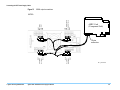
1
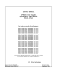
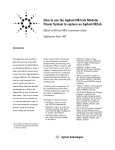
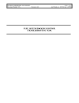
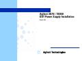
Agilent 3070 / 79000
DUT Power Supply Installation
October 2003
Contents
DUT Power Supply Installation
E4000-90021 Rev. J 10/2003
DUT Power Supply Installation 1
DUT Power Supply Installation
Introduction......................................................................................................................................2
Introduction................................................................................................................................2
Tools Needed .............................................................................................................................3
Preparation .................................................................................................................................3
Setting the DUT Power Supply Line Voltage .................................................................................8
Introduction................................................................................................................................8
6621A and 6624A Line Voltage Settings ................................................................................13
6634A Line Voltage Settings...................................................................................................16
6634B Line Voltage Settings ...................................................................................................18
6642A Line Voltage Settings...................................................................................................20
Installing DUT Power Supplies .....................................................................................................22
Introduction..............................................................................................................................22
Installing the DUT Power Supply in a 307X System ..............................................................23
Installing the DUT Power Supply in a 317X System ..............................................................24
Installing the DUT Power Supply in a 327X System ..............................................................30
Installing the DUT Power Supplies in a 79000 System...........................................................35
Connecting the DUT Power Supply Cables ..................................................................................41
Introduction..............................................................................................................................41
Connecting the Output Cables .................................................................................................41
Connecting the Overvoltage Shutdown Cables .......................................................................59
Connecting the Power and GPIB Cables .................................................................................69
Connecting Output, Overvoltage, Power and GPIB Cables in the 79000 ...............................74
Completing the Installation............................................................................................................76
6642A - Changing the Programming Mode ............................................................................76
Updating the Configuration Files ............................................................................................76
© Agilent Technologies 2000, 2002, 2003 Agilent 3070 / 79000 DUT Power Supply Installation
1
Table of Contents
Verifying Operation.................................................................................................................78
In Case of Difficulty ................................................................................................................78
Replacing the Covers ...............................................................................................................78
Installation Billing Information ...............................................................................................78
© Agilent Technologies 2000, 2002, 2003 Agilent 3070 / 79000 DUT Power Supply Installation
2
DUT Power Supply Installation
E4000-90021 Rev. J 10/2003
In this Manual...
© Agilent Technologies 2000–2003
■
Introduction, 2
■
Setting the DUT Power Supply Line Voltage, 8
■
Installing DUT Power Supplies, 22
■
Connecting the DUT Power Supply Cables, 41
■
Completing the Installation, 76
Agilent 3070 / 79000 DUT Power Supply Installation
1
Introduction
Introduction
This section contains:
■
Introduction, 2
■
Tools Needed, 3
■
Preparation, 3
Introduction
This document describes how to install DUT (device
under test) power supplies in the Agilent 3070 and
Agilent 79000 family systems. A DUT power supply
can be either a physical supply or a logical supply. A
physical supply is a box that might have one or more
logical supplies in it. For example, the 6624A has four
independent outputs, or four logical supplies. Logical
supplies can be split between two modules. Each logical
supply is assigned a unique number in the system and
board config files.1
The Agilent 3070 / 79000-supported DUT power
supplies are listed below (product no. (model no.)):
■
E3784A (6642A) 1-Output High-Current DUT
Power Supply
■
E3785A (faceless 6624A) 4-Output DUT Power
Supply
For ease of recognition, the supplies will be referred to
by their model numbers, as the 6624A, 6621A, 6634A,
6634B, 6642A, and faceless 6624A. Each kit includes
the power supply, a rack mount kit, overvoltage
protection cables, and in some cases, radiation shields.
The cables to connect the power supply to the ASRU
(Analog Stimulus and Response Unit) Card are included
with the testhead module. The ASRU and ASRU-B
cards used in most Series I testheads have only four
DUT power supply channels; the ASRU-C card in most
Series II testheads systems has six channels.
There are four basic steps to follow when installing one
or more DUT power supplies:
■
44940A (6624A) 4-Output DUT Power Supply
1 Determine the ac supply line voltage for the DUT
power supply and set up the DUT power supply line
input for this voltage.2
■
44941A (6621A) 2-Output High-Current DUT
Power Supply
2 Install the DUT power supply into the 3070 / 79000
testhead or support bay.
■
E4034A (6634A/B) 1-Output High-Voltage DUT
Power Supply
3 Connect the DUT power supply cables to the ASRU
Cards and DUT power supplies.
1 You set a logical supply’s value using the sps statement. See the Agilent 3070 Syntax Reference Manual for more information on using
the sps statement.
2 This changed in June 1999. See Setting the DUT Power Supply Line Voltage on page 8.
© Agilent Technologies2000–2003
Agilent 3070 / 79000 DUT Power Supply Installation
2
Introduction
4 Update the system configuration file for the
additional DUT power supply.
Each step might be simple or complex depending on
your application and system. Choose the appropriate
instructions for each step from the pages that follow.
Tools Needed
© Agilent Technologies2000–2003
Preparation
CAUTION
procedures in this document must be
✸ The
performed by personnel who are trained and
qualified to service Agilent 3070 / 79000 Family
systems.
■
Anti-static wrist strap
■
2.5-millimeter hex wrench
■
3-millimeter hex wrench
■
5-millimeter hex wrench
■
#2 Pozidriv screwdriver
■
1/4-inch flat blade screwdriver
■
T20 Torx driver
1 If the system is in use, notify the operator and system
administrator that testing must be suspended while
the DUT supply is installed. The testhead must be
shut down, but the controller can remain active for
use by programmers. Obtain permission before
shutting down the testhead.
■
Diagonal cutters
2 Remove any test fixture that may be on the testhead.
■
System cabinet key
■
Testhead key
3 Remove the board handler if it is installed on the
testhead.
■
Right-angle ratchet driver
■
T15 Torx bit for ratchet driver
■
T20 Torx bit for ratchet driver
■
Needle-nose pliers
■
7/16-inch box-end or open-end wrench
■
#2 Pozidriv ratchet or offset screwdriver
Agilent 3070 / 79000 DUT Power Supply Installation
Follow the steps below before beginning the
installation:
CAUTION
NOT rotate the testhead if an 44990A EFS
✸ DO
Board Handler is installed. The added weight of
the board handler might damage the testhead’s
rotating mechanism or cause the testhead to tip
over.
3
Introduction
Tools for removing the handler:
■
2.5-millimeter hex wrench
■
5-millimeter hex wrench
■
EFS removal cart and blower
NOTE
For instructions on removing the board handler,
refer to the procedure in the 44990A EFS Board
Handler Manual (44990-90004), Chapter 5. Save
all hardware.
4 Run Diagnostics, especially the DUT power supply
tests with a pin verification fixture. Correct any
problems detected before installing the DUT supply.
5 Turn power to the testhead OFF using these steps:
Execute testhead power off and switch the system
PDU(s) OFF.
CAUTION
beginning these installation procedures,
✸Before
verify that power to the testhead and support bay
is turned OFF. Execute a testhead power off
and switch the system PDU(s) OFF.
© Agilent Technologies2000–2003
Agilent 3070 / 79000 DUT Power Supply Installation
6 For 307X systems, it is not necessary but may be
helpful to remove the support bay covers as
described below (save all hardware):
a Using a cabinet key, open the front and rear doors.
You may remove the doors, but it’s not necessary.
b Using a #2 Pozidriv screwdriver, first remove the
top cover; it is held by two screws in the rear.
Then remove the left and right side covers; they
are each held by two screws at the top.
7 For 317X systems, remove the testhead covers (save
all hardware):
a Rotate the testhead to the 0-degree (shipping)
position.
b If the probe is in the probe holder on the safety
skirt, move it to a safe location.
c Using a 5-millimeter hex wrench, remove the
safety skirt.
d Using a T20 Torx driver, remove the top and
bottom covers; they are each held by one screw on
the front of the testhead.
e Rotate the testhead to the 90-degree (service)
position.
f Using a 1/4-inch flat blade screwdriver, remove
the rear cover.
4
Introduction
8 For 327X systems, remove the testhead covers (save
all hardware):
a Rotate the testhead to the 0-degree (shipping)
position.
b If the probe is in the probe holder on the safety
skirt, move it to a safe location.
c Using a 5-millimeter hex wrench, remove the
safety skirt.
79000 systems or the support bay of the 307X
system. The cables included in the various systems
and expansion kits are listed in Table 1 on page 6.
The cable ends are illustrated in Figure 1 on page 7.
11 If the DUT supply includes shorting straps on the
output terminals, remove them. Otherwise, remote
sensing will not work and the supply will fail
Diagnostics.
d Using a T20 Torx driver, remove the top cover.
e Rotate the testhead to the 90-degree (service)
position.
f Using a 1/4-inch flat blade screwdriver, remove
the rear cover.
9 For 79000 systems, remove the left pod cover (save
all hardware):
a If the probe is in the probe holder on the safety
skirt, move it to a safe location.
b Rotate the testhead to the 90-degree (service)
position.
c Using a 1/4-inch flat blade screwdriver, remove
the rear cover.
10 Inventory the kit. All bags in the kit are labeled.
Compare the part numbers and quantities of parts to
the Parts List in the kit. Report any discrepancies to
MTD before starting the installation. Find the cables
used to connect the DUT power supply to the ASRU
card, which were included with the module(s). They
should be coiled in the testhead of 317X, 327X or
© Agilent Technologies2000–2003
Agilent 3070 / 79000 DUT Power Supply Installation
5
Introduction
.
Table 1
DUT power supply output cable part numbers
System
Cable for ASRU Channels 1-4
Cable for ASRU Channels 5 & 6
307X
E4000-61602
E4000-61602
307X SI1
E4000-616212
E4000-616213
317X
E1170-61607
E4000-61606
327X
E1170-61607
E4000-61606
79000
E2190-61607
E2190-61606
1. Series I
2. This cable is provided in the kit E4000-80617, 307X Module Expansion Cables, which is used when adding a module to a
307X Series I to Series II expansion.
3. This cable is used for Channels 5 and 6 only if the system has ASRU-C cards.
© Agilent Technologies2000–2003
Agilent 3070 / 79000 DUT Power Supply Installation
6
Introduction
Figure 1
Illustrations of cable ends. Top left: DUT power supply end of E4000-61602, E1170-61607, E2190-61607 and
E4000-61621 cables with four 4-spade lug connectors and a ground banana plug. Top Right: ASRU Card end of the same cables
with a 34-pin connector and ground lug connector. Bottom Left: DUT power supply end of E4000-61602, E4000-61606,
E2190-61606 and E4000-61621 cables with spade lug connectors; note that each wire is labeled and numbered.
Bottom Right: ASRU-C Card end of the same cables with a 20-pin connector.
cables.wpg
© Agilent Technologies2000–2003
Agilent 3070 / 79000 DUT Power Supply Installation
7
Setting the DUT Power Supply Line Voltage
Setting the DUT
Power Supply Line
Voltage
This section contains:
■
Introduction, 8
■
6621A and 6624A Line Voltage Settings, 13
■
6634A Line Voltage Settings, 16
■
6634B Line Voltage Settings, 18
■
6642A Line Voltage Settings, 20
Introduction
Based on the power option of the system, determine the
DUT supply line voltage using Table 3 on page 10.
Then proceed with the instructions for the model of
DUT power supply you are installing on the pages that
follow the table.
NOTE
Beginning with the serial number shown in Table
2 on page 9, all DUT power supplies in Agilent
3070 / 79000 Series 3 systems are factory
configured to 220 volts or 240 volts, as shown in
Table 3 on page 10. The outlets where the DUT
power supplies are connected to power may also
have been modified, as described in Repair >
Power Subsystems > DUT Power Supplies.
© Agilent Technologies2000–2003
Agilent 3070 / 79000 DUT Power Supply Installation
8
Setting the DUT Power Supply Line Voltage
Table 2
Series 3 / 79000 power requirement reduction beginning serial numbers
System Type
79000
327X
317X
307X
Testhead Product
E2190A
E9997A
E9998A
E9900A
Serial Number
US38050109
US38240151
US38240242
US38240239
The Testhead product number and serial number are
located on the rear, lower right side on the
cross-member of the testhead.
© Agilent Technologies2000–2003
Agilent 3070 / 79000 DUT Power Supply Installation
9
Setting the DUT Power Supply Line Voltage
Table 3
DUT power supply line voltage setting
3-Phase Wye with Neutral
L1
N
L2
L3
G
Three-Phase Delta
L3
L2
L1
Power Option
Phase Voltage
DUT Supply Line Voltage
AWW
208V
220V
05E
220V
220V
0E5
380V
220V
05L
400V
240V
0E7
415V
240V
0ED
200V
220V
05C
220V
220V
05H
230V
240V
0E6
240V
240V
05B
220V
220V
05G
230V
240V
05K
240V
240V
G
Single-Phase Wye with
Neutral
L1
L2
N
G
© Agilent Technologies2000–2003
Agilent 3070 / 79000 DUT Power Supply Installation
10
Setting the DUT Power Supply Line Voltage
Table 3
DUT power supply line voltage setting (continued)
Single-Phase Earthed
L1
Power Option
Phase Voltage
DUT Supply Line Voltage
05M
220V
220V
05F
230V
240V
05J
240V
240V
AWX
200V
220V
0EB
220V
220V
0EJ
230V
240V
0EC
240V
240V
AWY
200V
220V
0E3
220V
220V
0EG
230V
240V
0EH
240V
240V
N
G
Single-Phase Non-Earthed
L1
L2
G
Single-Phase Center-Tap
Neutral
L1
N
L2
G
© Agilent Technologies2000–2003
Agilent 3070 / 79000 DUT Power Supply Installation
11
Setting the DUT Power Supply Line Voltage
NOTE
Option 05A is not available on the Corporate
Price List (CPL) after June 1999. The DUT power
supplies input voltage for Japanese systems are set
to 220 volts at the factory and the neutral center
tap is no longer used.
If 3-phase delta (0ED) power is not available, use
1-phase 200-volt option (AWY) and two PDUs.
For 3070 Series II systems, see Appendix A,
"Power Requirements for Older Systems."
© Agilent Technologies2000–2003
Agilent 3070 / 79000 DUT Power Supply Installation
12
Setting the DUT Power Supply Line Voltage
6621A and 6624A Line Voltage Settings
The 6621A and 6624A supplies can be set to accept ac
input voltage of 100, 120, 220, or 240 volts by
Figure 2
positioning the voltage selector card located inside of
the line module. Figure 2 shows the location of the
power module.
6624A and 6621A line input power module location
Line input power module
rear662x.wpg
© Agilent Technologies2000–2003
Agilent 3070 / 79000 DUT Power Supply Installation
13
Setting the DUT Power Supply Line Voltage
The procedure for changing the input line voltage is as
follows.
1 Remove the power card from the ac input socket on
the back of the power supply.
2 To open the power module, move the plastic door on
the module aside. If your line voltage change
requires a change in rating of the fuse, rotate FUSE
PULL to the left and remove the fuse (see Figure 3
on page 15).
3 Grasp the voltage selector PC board with a pair of
needle-nose pliers and slide it out of its slot.
4 To select a voltage, orient the PC board so that the
desired voltage appears on the top left side of the
board (see Figure 3 on page 15). Push the board all
the way back into its slot. The desired line voltage
must be visible through the module window when the
board is installed.
© Agilent Technologies2000–2003
Agilent 3070 / 79000 DUT Power Supply Installation
14
Setting the DUT Power Supply Line Voltage
Figure 3
6624A and 6621A voltage select PC board
s
ice
o
h des
rd
Vo
on ltage
of p both c
c b si
oa
Line input
power module
F1
Voltage Select PC Board
Operating voltage is shown in module window
6628pow.wpg
© Agilent Technologies2000–2003
Agilent 3070 / 79000 DUT Power Supply Installation
15
Setting the DUT Power Supply Line Voltage
5 Install the correct fuse in the door of the line module
if your line voltage change also requires a change in
the rating of the fuse (see Table 4).
Table 4
Agilent 6624A and 6621A fuse requirements
Line Voltage
Fuse Needed
Part Number
100/120 V
8 AF/250V
2110-0342
220/240 V
4 AF/250V
2110-0055
WARNING
✸
Make sure the replacement fuse type (size) and
rating (current, speed, and voltage) is consistent
with the voltage level you are operating at. Using
a substitute fuse could result in a fire hazard.
6 Close the door of the line module and insert the
power cord in the ac input socket. Your power supply
is now configured to operate at the voltage you
selected.
© Agilent Technologies2000–2003
Agilent 3070 / 79000 DUT Power Supply Installation
6634A Line Voltage Settings
The 6634A supply can be set to accept 100, 120, 220 or
240 volts ac input. You can convert line voltage by
setting three components: two line select switches (S2
and S3) and the rear panel fuse (F1). To convert the
supply from one line voltage to another, proceed as
follows:
1 Turn off the supply and use a #2 Pozidriv screwdriver
to remove the top cover by removing five screws:
two M5 on each side and one M4 on the rear panel.
2 Locate the line voltage select switches S2 and S3 (see
Figure 4 on page 17).
16
Setting the DUT Power Supply Line Voltage
Figure 4
6634A line voltage selection
T1
S2
U1
C26
S3
U2
Terminal
Block
U3
GPIB
Connector
Fuse (F1)
© Agilent Technologies2000–2003
Agilent 3070 / 79000 DUT Power Supply Installation
Line Receptacle
6632ps.wpg
17
Setting the DUT Power Supply Line Voltage
3 Note that each switch has two positions.
Representations of these positions are silkscreened
on the PC board next to the switches. To change the
line voltage, consult the silkscreen drawing and set
the switches accordingly.
Table 5
4 Check the rating of the fuse (F1) installed in the rear
panel fuse holder and replace with the correct fuse if
necessary. Use Table 5 to determine the proper fuse.
6634A fuse requirements
Line Voltage
Fuse Needed
Part Number
100/120 V
4 AF/250V
2110-0055
220/240 V
2 AF/250V
2110-0002
WARNING
sure the replacement fuse type (size) and
✸Make
rating (current, speed, and voltage) is consistent
with the voltage level you are operating at. Using
a substitute fuse could result in a fire hazard.
6634B Line Voltage Settings
3 Slightly spread the bottom rear of the cover and pull
it back to disengage it from the unit.
4 Locate the ac input wiring harness on the left side of
the transformer.
5 Use needlenose pliers and connect the ac input
wiring harness according to the information in
Figure 5.
The 6634B supply is set at the factory for 120 volt line
power. The 6634B supply can be set to accept 100, 120,
220 or 240 volts ac input by setting the jumpers on the
power transformer as shown in Figure 5 on page 19.
1 Turn off power to the supply and disconnect the
power cord from the power source.
2 Remove the four screws that secure the two carrying
straps and outer cover.
© Agilent Technologies2000–2003
Agilent 3070 / 79000 DUT Power Supply Installation
18
Setting the DUT Power Supply Line Voltage
Figure 5
© Agilent Technologies2000–2003
6634B line voltage selection
Agilent 3070 / 79000 DUT Power Supply Installation
19
Setting the DUT Power Supply Line Voltage
6642A Line Voltage Settings
The 6642A supply can be set to accept 100, 120, 220 or
240 volts ac input by setting the line voltage select
switches.
1 Turn off power to the supply and disconnect the
power cord from the power source.
Figure 6
2 Remove the four screws that secure the two carrying
straps and outer cover.
3 Slightly spread the bottom rear of the cover and pull
it back to disengage it from the front panel.
4 Slide the dust cover back far enough to expose the
select switches (see Figure 6).
6642 line voltage selection
AC line voltage
switch settings
6642pow.wpg
5 Move the line voltage select switches to the positions
corresponding to the desired line voltage.
6 Replace the top cover and secure the carrying straps.
7 Change the line fuse (on the rear panel) to the proper
value for the new line voltage (see Table 6 on
page 21).
© Agilent Technologies2000–2003
Agilent 3070 / 79000 DUT Power Supply Installation
20
Setting the DUT Power Supply Line Voltage
Table 6
6642A fuse requirements
Line Voltage
Fuse Needed
Part Number
100 V
6 AF/250V
2110-0056
120 V
5 AF/250V
2110-0010
220/230/240 V
3 AF/250V
2110-0003
WARNING
sure the replacement fuse type (size) and
✸Make
rating (current, speed, and voltage) is consistent
with the voltage level you are operating at. Using
a substitute fuse could result in a fire hazard.
© Agilent Technologies2000–2003
Agilent 3070 / 79000 DUT Power Supply Installation
21
Installing DUT Power Supplies
Installing DUT
Power Supplies
Introduction
This section contains:
■
Introduction, 22
■
Installing the DUT Power Supply in a 307X System, 23
■
Installing the DUT Power Supply in a 317X System, 24
■
Installing the DUT Power Supply in a 327X System, 30
■
Installing the DUT Power Supplies in a 79000 System,
35
This section describes how to install the DUT power
supply in the module or support bay. Proceed to the
section with instructions for a particular 3070 System.
To identify which model of system you are working on,
read the Common Testhead Product Number, which is
printed on the serial number label on the rear of the
cradle. Refer to Table 7 to relate the Common Testhead
product number to a model number.
The 79000 Functional Test System does not have a
common testhead number.
Table 7
Common testhead product numbers
System Model
Series I Testhead
Series II Testhead
Series III Testhead
307X (4-module Testhead)
E1171A
E4026A
E9900A
317X (2-module Testhead)
E1170A
E4025A
E9998A
327X (1-module Testhead)
N/A
E3770A
E9997A
In the 307X, 317X and 327X systems, you must install a
radiation shield along with the DUT power supply. The
79000 system does not require the radiation shield.
When installing a high-voltage 6634A/B DUT power
supply in a 317X, you must install the shield
E4034-00601, shown in Figure 7 on page 23. When
installing a Faceless 6624A or a high-voltage 6634A/B
in a 327X, you must install the shield E3770-00601
© Agilent Technologies2000–2003
Agilent 3070 / 79000 DUT Power Supply Installation
(also shown in Figure 8 on page 25) unless one is
already installed.
22
Installing DUT Power Supplies
Figure 7
Radiation shields for the DUT power supplies 6634A/B and 6624A
Shield No.
E4034-00601
for 6634A in
317X
Testheads
Shield No.
E3770-00601 for
DUT Power
Supplies in the
327X Testhead
shields.wpg
These shields prevent the DUT power supply from
radiating into the nearby ASRU cards causing
measurement failures. Instructions for installing these
shields are included in the procedures below, where
appropriate.
3 From the front of the support bay, slide the power
supply onto the support rails at the exposed location.
4 Using a #2 Pozidriv screwdriver, secure the power
supply rack-mount ears to the front of the support
bay using 4 each dress screws (0570-1366)
Installing the DUT Power Supply in a 307X
System
1 Remove the adhesive-backed trim strips from the
sides of the power supply’s front frame. Then, using
a #2 Pozidriv screwdriver, install rack-mount ears on
both sides of the power supply. Pan-head screws are
included with the rack-mount ears.
2 Remove the filler panel from the lowest available
slot.
© Agilent Technologies2000–2003
Agilent 3070 / 79000 DUT Power Supply Installation
23
Installing DUT Power Supplies
Installing the DUT Power Supply in a 317X
System
These procedures describe how to install the DUT
power supply in a 317X testhead. If you are installing an
6634A/B DUT power supply, there are some additional
steps described below to install a radiation shield
(E4034-00601), which is integrated into a new power
supply support rail.
1 Using a #2 Pozidriv screwdriver, remove the side
handles from both sides of the power supply. Discard
these parts.
2 Remove the adhesive-backed trim strips from the
sides of the power supply’s front frame. Then, using
a #2 Pozidriv screwdriver, install rack-mount ears on
both sides of the power supply. Pan-head screws are
included with the rack-mount ears.
3 On the top of the testhead is a sheet metal cover
(E1170-01208) over the bank containing the power
supplies. Remove the four T15 screws that attach the
cover to the testhead frame.
4 Using a 7/16-inch box or open-end wrench, remove
the hex-head screws, split lockwashers, and flat
washers from the rear of the testhead (see Figure 8
on page 25).
5 Using a #2 Pozidriv offset or ratchet screwdriver,
remove the DUT power supply mounting bars from
the support rails shown in Figure 8. Save the
flat-head Pozidriv screws.
© Agilent Technologies2000–2003
Agilent 3070 / 79000 DUT Power Supply Installation
24
Installing DUT Power Supplies
Figure 8
Locating the DUT power supply mounting bars in a 317X system
Support Rails
Mounting Bars
Hex-Head Screws
dutrail.wpg
© Agilent Technologies2000–2003
Agilent 3070 / 79000 DUT Power Supply Installation
25
Installing DUT Power Supplies
6 Using a #2 Pozidriv screwdriver and the screws
removed in step 4, install the mounting bars on the
sides of the power supply.
7 If installing a 6634A/B power supply, remove the
existing support rail on the left side of the rack;
otherwise, skip this step. Install the new combination
shield/support rail (E4034-00601) on the left side of
the rack. The orientation of the shield/support rail in
the testhead is illustrated in Figure 9 on page 27.
© Agilent Technologies2000–2003
Agilent 3070 / 79000 DUT Power Supply Installation
26
Installing DUT Power Supplies
Figure 9
Front view of the testhead showing the orientation of an E4034-00601 shield/support rail used with an 6634A/B
E4034-00601
Combination
Shield/Support Rail
Slot where
6634A/B Power
Supply will be
added
Existing Power Supply
© Agilent Technologies2000–2003
Agilent 3070 / 79000 DUT Power Supply Installation
shld_ft.wpg
27
Installing DUT Power Supplies
8 Slide the power supply into the testhead from the
front.
9 Using a #2 Pozidriv screwdriver, secure the power
supply rack-mount ears to the front of the testhead
using 4 each dress screws (0570-1366).
10 Replace the sheet metal cover (E1170-01208) on the
top of the testhead using the four T15 screws
removed in step 3 on page 24.
11 Using a 7/16-inch box or open-end wrench, replace
the hardware removed in step 3, securing the power
supply mounting bars in the testhead as shown in
Figure 10 on page 29.
© Agilent Technologies2000–2003
Agilent 3070 / 79000 DUT Power Supply Installation
28
Installing DUT Power Supplies
Figure 10
Installing the DUT power supply in a 317X system
Mounting Bars
dutinsta.wpg
© Agilent Technologies2000–2003
Agilent 3070 / 79000 DUT Power Supply Installation
29
Installing DUT Power Supplies
Installing the DUT Power Supply in a 327X
System
These procedures describe how to install the DUT
power supply in a 327X testhead. If you are installing a
Faceless 6624A or an 6634A/B DUT power supply,
there are some additional procedures, as indicated
below. If it is not already present, a radiation shield
(E3770-00601) must be mounted onto the existing
support rails. Without this shield in place, the power
supply might radiate into nearby ASRU cards causing
measurement failures. This procedure is to be done only
by Agilent 3070 / 79000 service-trained customer
engineers.
1 Use a #2 Pozidriv screwdriver to remove the side
handles from both sides of the power supply.
Discard these parts.
2 Determine the location for the power supply using
Figure 11 on page 31.
© Agilent Technologies2000–2003
Agilent 3070 / 79000 DUT Power Supply Installation
30
Installing DUT Power Supplies
Figure 11
327X DUT power supply locations
HP 6634A
Top or
Slot
HPfor6642A
6634A/B or 6642A
Location of
Radiation Shield
E3770-00601
Bottom Slot for
HP 6624A
6621A
6624AororHP
6621A
6634A
parsps1.wpg
© Agilent Technologies2000–2003
Agilent 3070 / 79000 DUT Power Supply Installation
31
Installing DUT Power Supplies
3 Determine whether the radiation shield
(E3770-00601) is installed in the bottom DUT power
supply slot. Figure 11 on page 31 shows the location
of the radiation shield. If the shield is not in place,
you must remove the power supply in the bottom slot
(if one is present) and install the shield, as described
in the next step; if the shield is in place, skip the next
step.
4 To install the radiation shield, remove all wires and
the power cord from the rear of the 6624A or 6621A
power supply, noting where they were connected.
Remove the power supply from the front of the
testhead. Install the radiation shield as shown in
Figure 12 on page 33, and fasten with the four
screws provided using a #2 Pozidriv screwdriver.
Reinstall the power supply. Reconnect the wires and
power cord to the power supply.
© Agilent Technologies2000–2003
Agilent 3070 / 79000 DUT Power Supply Installation
32
Installing DUT Power Supplies
Figure 12
Location of the DUT power supply shield E3770-00601
Slot for the 6624A or 6621A
power supply with the E377000601 DUT power supply
shield in place in the
327X Testhead
327Xshield.wpg
5 If the supply will be placed in the side slot, use a #2
Pozidriv screwdriver to install rack-mount ears on
© Agilent Technologies2000–2003
Agilent 3070 / 79000 DUT Power Supply Installation
both sides of the power supply so that the front of the
ears are back from the front of the power supply (see
33
Installing DUT Power Supplies
Figure 13). Pan-head screws are included with the
rack-mount ears. Using a #2 Pozidriv screwdriver,
secure the power supply rack-mount ears to the
Figure 13
mounting bars in the testhead using 4 dress screws
(0570-1366).
Attaching the rack mount ear to a side mounted 6634A/B power supply
Front of Power Supply
Rack Mount Ear
RACKEAR.WPG
6 If the supply will be placed in the top slot, use a #2
Pozidriv screwdriver to install rack mount brackets
on both sides of the power supply in the normal way
with the ears flush with the front panel of the power
© Agilent Technologies2000–2003
Agilent 3070 / 79000 DUT Power Supply Installation
supply. Pan-head screws are included with the
rack-mount ears. Using a #2 Pozidriv offset or ratchet
screwdriver, attach the DUT power supply mounting
brackets to the rack slides.
34
Installing DUT Power Supplies
Installing the DUT Power Supplies in a 79000
System
These procedures describe how to install a DUT supply
in a 79000 testhead. The cables for both the 6624A and
6634A/B are installed in all 79000 testheads, even if
DUT supplies are not factory installed. All necessary
hardware is shipped attached to the cradle in the left pod
to install each of DUT supplies.
In the 79000 system, the DUT supplies are mounted in
the pod on the right end, when viewed from the back of
the system, as shown in Figure 14 on page 36. The
6624A (E3785A faceless DUT power supply), and up to
two 6634A/Bs (1-output high voltage E4034A DUT
power supply) may be installed in the 79000 system. If
there is only one 6634A/B, it is installed in the middle
position. The face down 6634A/B is installed next to the
cradle wall. The 6624A is installed in the outside
position.
NOTE
If two 6634A/Bs are installed, the face down
6634A/B must be installed before the middle
6634A/B due to access constraints.
© Agilent Technologies2000–2003
Agilent 3070 / 79000 DUT Power Supply Installation
35
Installing DUT Power Supplies
Figure 14
79000 DUT power supply locations
P.S. Mounting
Bracket #1
P.S. Mounting
Bracket #2
Outside 6624A
Middle
6634A/B
Installed
Face down
6634A/B
Installed
© Agilent Technologies2000–2003
Agilent 3070 / 79000 DUT Power Supply Installation
79k_
36
Installing DUT Power Supplies
Middle 6634A/B DUT Supply Installation
Figure 15
Power supply rear mounting bracket
NOTE
If two 6634A/Bs (E4034A) are to be installed,
install the face down power supply nearest the
cradle first. Access to the face down supply is not
possible after the middle 6634A/B is installed.
The middle 6634A/B is installed first, if there is
only one 6634A/B in the system, to improve
access to the front panel.
Power
plug
Mounting
Bracket
1 If you have not already done so, using a #2 Pozidriv
screwdriver remove power supply mounting bracket
#1, shown in Figure 14 on page 36, from power
supply mounting bracket #2.
2 Using a #2 Pozidriv screwdriver, remove the screw
nearest the ac power plug. It is on the side of the
6634A/B where there is not a handle. This is the side
that will mount next to the bottom of the pod.
3 Using a #20 Torx driver, remove the mounting
bracket from the cradle DUT mounting support,
shown in Figure 15. Attach the bracket to the
6634A/B using the mounting screw removed in
step 1. The mounting bracket should be oriented as
shown in Figure 15.
Mounting Screws
Cradle DUT
Mounting Support
6634r_mt
4 Mount the rack mount ear on the front of the
6634A/B on the front of the power supply on the side
with no handle. The other rack mount ear included in
the kit will not be used.
© Agilent Technologies2000–2003
Agilent 3070 / 79000 DUT Power Supply Installation
37
Installing DUT Power Supplies
5 Install the 6634A/B in the middle location, shown in
Figure 14, by setting the power supply in the middle
slot and using two screws to secure the mounting
bracket to the cradle DUT mounting support.
6 Using a #1 Pozidriv screwdriver and 2 dress screws
(0570-1366), secure the 6634A/B to the cradle DUT
mounting support using the rack mount ears as
shown in Figure 16.
Figure 16
Power supply front mounting
Cradle DUT
Mounting Support
6624
7 If a 6624A supply needs mounted, go to 6624A DUT
Supply Installation. If a 6624A does not need
mounted, reinstall mounting bracket number #1. The
correct mounting is shown in Figure 14 on page 36.
Agilent 3070 / 79000 DUT Power Supply Installation
1 Using a #2 Pozidriv screwdriver remove power
supply mounting bracket #1, shown in Figure 14 on
page 36, from power supply mounting bracket #2. If
a middle 6634A/B or an 6624A is already installed,
remove power supply mounting bracket #1 from
them and set the bracket and the screws aside for
later use. The middle 6634A/B will need to be
removed to install the face down 6634A/B.
2 Plug in the face down 6634A/B and set the GPIB
address to 3. Since front panel access is not possible
after mounting, this must be done before mounting
the power supply. See the section Programming the
GPIB Address on Supplies with Front Panels on
page 72 for instructions.
Rack Mount Ears
with Dress Screws
© Agilent Technologies2000–2003
Face Down 6634A/B DUT Supply Installation
3 The face down 6634A/B is mounted next to the
cradle. There are two mounting brackets included in
each Agilent 79000, one on each end of where the
face down 6634A/B is installed. Remove the
mounting brackets from the cradle frame, front and
rear, and attach them to the power supply using the
0515-0383 screws in the plastic bag tied to the cradle
DUT mounting support. First attach the 6634A/B
mounting bracket to the power supply using the
slotted holes, but do not tighten them. Insert the face
down 6634A/B with the GPIB connector toward the
front of the system and re-attach the mounting
brackets to the cradle frame, shown in Figure 17 on
page 39, using two screws in both the front and rear
to secure the power supply to the cradle. Next tighten
the screws in the slotted holes to secure the power
supply to the cradle.
38
Installing DUT Power Supplies
Figure 17
Second 6634A front mounting bracket
number #1. The correct mounting of mounting
bracket #1 is shown in Figure 14 on page 36.
6624A DUT Supply Installation
1 If you have not already done so, using a #2 Pozidriv
screwdriver remove power supply mounting bracket
#1, shown in Figure 14, from power supply
mounting bracket #2.
6634A/B Mounting
Brackets with Screws
2 Using a #2 Pozidriv screwdriver, remove the side
handle nearest the ac power plug. This is the side that
will mount next to the cradle DUT mounting support.
3 Using a #20 Torx driver, remove the mounting
bracket from the cradle DUT mounting support,
shown in Figure 18. Attach the bracket to the 6624A
using the mounting hole which originally held the
bottom side handle nearest the 6624 power plug.
Cradle Frame
6634#2mt
4 If additional supplies require mounting, use the
mounting instructions for the middle 6634A/B or
6624A as appropriate. If no additional DUT supplies
are to be mounted, reinstall mounting bracket
© Agilent Technologies2000–2003
Agilent 3070 / 79000 DUT Power Supply Installation
39
Installing DUT Power Supplies
Figure 18
6624A rear mounting bracket
Mounting
Bracket
Power
plug
Mounting Screws
Cradle DUT
Mounting Support
5 Install the 6624A in the outside most location, shown
in Figure 18 on page 40 by setting the power supply
in the outside slot and using two screws to secure the
mounting bracket to the cradle DUT mounting
support.
6 Using a #1 Pozidriv screwdriver and 2 dress screws
(0570-1366), secure the 6624A to the cradle DUT
mounting support using the rack mount ears, as
shown in Figure 16 on page 38.
7 If additional supplies require mounting, use the
mounting instructions for that power supply. If no
additional DUT supplies are to be mounted, reinstall
mounting bracket number #1. The correct mounting
of mounting bracket #1 is shown in Figure 14 on
page 36.
4 Mount a rack mount ear on the front of the 6624A
power supply on the side with the handle removed.
The other rack mount ear included in the kit will not
be used.
© Agilent Technologies2000–2003
Agilent 3070 / 79000 DUT Power Supply Installation
40
Connecting the DUT Power Supply Cables
Connecting the DUT
Power Supply
Cables
This section contains:
Output, Overvoltage, Power and GPIB Cables in the
79000 on page 74.
■
Introduction, 41
■
Connecting the Output Cables, 41
Connecting the Output Cables
■
Connecting the Overvoltage Shutdown Cables, 59
■
Connecting the Power and GPIB Cables, 69
■
Connecting Output, Overvoltage, Power and GPIB
Cables in the 79000, 74
This section describes how to connect the output cables
for the DUT power supplies. These instructions are for a
system being configured for the first time. Table 8
shows the various models of programmable DUT power
supplies available.
Introduction
NOTE
You install four types of cables with the DUT power
supply: the output cable, overvoltage cable, power cord,
and GPIB cable. These sections describe how to connect
each of these cables, as well as how to program the
GPIB address in the DUT power supply.
The 79000 system has the cables for two 6634A/Bs and
one 6624A installed in the testhead in the factory. The
cable connections for the output cables, over voltage
cables and GPIB cables are shown in Connecting
Table 8
© Agilent Technologies2000–2003
When adding a supply, the configuration of
existing supplies may prevent you from following
all of these procedures. Do not reconfigure
existing supplies. Reconfiguring existing supplies
is likely to cause previously developed board tests
to fail.
DUT power supplies
Product No.
Model No.
Description
44940A
E3785A1
6624A
4 outputs: 2 @ 0-7 V, 0-5 A or 0-20 V,
0-2 A and
2 @ 0-20 V, 0-2 A or 0-50 V, 0-0.8 A
44941A
6621A
2 outputs: 0-7 V, 0-10 A or 0-20 V, 0-4 A
E4034A
6634A/B2
1output: 1-100 V, 0-1 A
Agilent 3070 / 79000 DUT Power Supply Installation
41
Connecting the DUT Power Supply Cables
Table 8
DUT power supplies
Product No.
Model No.
Description
E3784A
6642A
1 output:0-20 V, 0-10 A
1. The 44940A is a standard 6624A supply; the E3785A is a faceless 6624A supply.
2. This supply requires the 03066-66532 ASRU-C Card.
The cables used to connect the DUT power supplies
were included with the module(s). You should find the
cables coiled in the testhead of 317X or 327X systems
or in the support bay of the 307X system. The cable
numbers are listed in Table 1 on page 6. The cable
connector ends are illustrated in Figure 1 on page 7; the
ASRU Card end of the cable can be either a 34-pin
connector or a 20-pin connector. The 34-pin connector
is for ASRU channels 1-4, and the 20-pin connector is
for channels 5-6, found only on ASRU-C Cards.
The ASRU Card is illustrated in Figure 19 on page 43.
The DUT power supply connections are J4 and J9. J9 is
present only on ASRU-C Cards.
© Agilent Technologies2000–2003
Agilent 3070 / 79000 DUT Power Supply Installation
42
Connecting the DUT Power Supply Cables
Figure 19
ASRU card connectors
1
78
P1 - To Mother Card
J2 - Fixture Interface Pins
J156
ASRU Card
Probe
J155
WHT
RED
(Component Side)
J8 J7 J5 J6
1
2
3
4
Functional Ports
33
34
J4
1
2
19
J9
20
1
2
DUT Power Supply Connectors
Figure 20 on page 44 provides a close-up view of one
side of the rear of two Agilent 6624A four-output DUT
power supplies with the output cables, overvoltage
cables, and GPIB cables installed. (The power cord
© Agilent Technologies2000–2003
Agilent 3070 / 79000 DUT Power Supply Installation
Calibration Jumper
Connector
ASRU.wpg
connects to the right side of the rear of the power supply
and is out of view in this illustration).
43
Connecting the DUT Power Supply Cables
Figure 20
Left rear view of two 6624A DUT power supplies with cables installed
GPIB
connector
Two 4-spade
lug connectors
Banana plug
Overvoltage
cables
Two GPIB
connectors
DUTback.wpg
© Agilent Technologies2000–2003
Agilent 3070 / 79000 DUT Power Supply Installation
44
Connecting the DUT Power Supply Cables
© Agilent Technologies2000–2003
Agilent 3070 / 79000 DUT Power Supply Installation
45
Connecting the DUT Power Supply Cables
NOTE
The pins in the DUT power supply connector on
the rear of the ASRU Card are easily bent. Always
check them before plugging in the DUT power
supply cable. When installing a connector, align
the connector with the plugs carefully, and apply
pressure evenly across the connector to keep from
bending pins.
Proceed with the instructions for the model of power
supply you are installing on the pages that follow.
© Agilent Technologies2000–2003
Agilent 3070 / 79000 DUT Power Supply Installation
46
Connecting the DUT Power Supply Cables
6624A (44940A and E3785A) Supplies
The 6624A is a 4-output DUT power supply. One
ASRU channel is required for each output.
1 Locate the highest numbered module with channels 1
through 4 available on the ASRU Card; if channels 1
through 4 are not available, go to step 2. Connect the
DUT Power Supply cable (E4000-61602 for a 307X
system or E1170-61607 for a 317X or 327X system)
to the ASRU Card and to the 6624A supply, as
illustrated in Figure 21.
© Agilent Technologies2000–2003
Agilent 3070 / 79000 DUT Power Supply Installation
47
Connecting the DUT Power Supply Cables
Figure 21
6624A output connections
GRN
RED & WHT/RED
BLK & WHT/BLK
WHT
WHT
ORN/WHT
RED/WHT
RED
6624A
ASRU Card
(Component Side)
© Agilent Technologies2000–2003
Agilent 3070 / 79000 DUT Power Supply Installation
BLK
BLK/WHT
BRN/WHT
WHT
WHT
GRN/WHT
BLU/WHT
BLU
34-pin
connector
DUT_PS1.WPG
48
Connecting the DUT Power Supply Cables
2 If channels 1 through 4 are not available in any
module, cable the 6624A supply to a bank where
both modules have channels 5 and 6 available. Split
the outputs as shown in Figure 22 on page 50. Notice
that output 2 goes to channel 5 and output 4 goes to
channel 6 on the ASRU Card in the higher numbered
module. It is possible that there will not be enough
ASRU Card channels available to use all of the
power supply outputs. Output 1 goes to channel 5
and output 3 goes to channel 6 on the ASRU Card in
the lower numbered module in the same bank. To
connect all of the outputs, two cables are necessary
since the outputs will go to two modules. Use two
E4000-61602 cables for a 307X system or two
E4000-61606 cables for a 317X system; remember to
connect the banana plug ground on the back of the
power supply and the ground lug connector to the
ASRU Card.
NOTE
A 6624A would not normally be connected to
ports 5 and 6 in a 327X system since these are
reserved for the higher voltage 6634A/B power
supplies.
© Agilent Technologies2000–2003
Agilent 3070 / 79000 DUT Power Supply Installation
49
Connecting the DUT Power Supply Cables
Figure 22
Alternate 6624A output connections
5-BLU
8-RED/WHT
7-ORN/WHT
6-WHT
E1170-61606 colors
Channel 6
E4000-61602 colors
5-BLU
8-BRN/BLK
7-ORN
6-WHT
Channel 5
2-WHT
3-BRN
4-BRN/BLK
1-GRN
2-WHT
3-BRN/WHT
4-BLK/WHT
1-GRN
6624A
ASRU card of
higher numbered
module
20-pin connector
E1170-61606 colors
1-GRN
4-BRN/BLK
3-BRN
2-WHT
E4000-61602 colors
Channel 5
20-pin connector
1-GRN
4-BLK/WHT
3-BRN/WHT
2-WHT
6-WHT
7-ORN/WHT
8-RED/WHT
5-BLU
Channel 6
6-WHT
7-ORN
8-BRN/BLK
5-BLU
ASRU card of
lower numbered
module
DUT_PS3.WPG
© Agilent Technologies2000–2003
Agilent 3070 / 79000 DUT Power Supply Installation
50
Connecting the DUT Power Supply Cables
6621A (44941A) Supply
The 6621A is a 2-output, high-current DUT power
supply. Two ASRU channels are required for each
output to handle the high current.
1 Cable the 6621A supplies starting in the highest
numbered module. If the 6621A is the first supply for
the module, use channels 1 through 4 on the ASRU
Card with output 1 going to channels 1 and 4 and
output 2 going to channels 2 and 3. Connect cable
E4000-61602 for a 307X system or E1170-61607 for
a 317X or 327X system as shown in Figure 23 on
page 52.
© Agilent Technologies2000–2003
Agilent 3070 / 79000 DUT Power Supply Installation
51
Connecting the DUT Power Supply Cables
Figure 23
6621A output connections
Channels
2 and 3
WHT
ORN/WHT
RED/WHT
RED
WHT
GRN/WHT
BLU/WHT
BLU
6621A
Two 4-spade lug
connectors with
these colors stacked
ASRU Card
(Component Side)
34-pin
connector
GRN
RED
BLK
WHT
BLK
BLK/WHT
BRN/WHT
WHT
Channels
1 and 4
© Agilent Technologies2000–2003
Agilent 3070 / 79000 DUT Power Supply Installation
Two 4-spade lug
connectors with
these colors
stacked
DUT_PS4.WPG
52
Connecting the DUT Power Supply Cables
2 If you are using ASRU Card channels 1 through 4,
connect the 6621A so output 2 goes to channels 5 and
6 in the higher numbered module, and output 1 goes
to channels 5 and 6 in the lower numbered module in
the same bank. It is possible that there will not be
enough ASRU Card channels available to use both of
the power supply outputs. To connect all of the
outputs, two cables are necessary since the outputs
will go to two modules. Use two E4000-61602 cables
for a 307X system or two E4000-61606 cables for a
317X system and connect the cables as shown in
Figure 24 on page 54.
NOTE
A 6621A can not be connected to ports 5 and 6 in
a 327X system.
© Agilent Technologies2000–2003
Agilent 3070 / 79000 DUT Power Supply Installation
53
Connecting the DUT Power Supply Cables
6621A
Channels
5 and 6
Alternate 6621A output connections
6-WHT
2-WHT
3-BRN/RED 7-ORN/RED
4-BLK/RED 8-RED/BLK
1-GRN
5-BLU
Figure 24
Two 4 spade lug
connectors with
these colors stacked
ASRU card of
higher numbered
module
20-pin connector
ASRU card of
lower numbered
module
1-GRN
5-BLU
8-RED/BLK 4-BLK/RED
7-ORN/RED 3-BRN/RED
2-WHT
6-WHT
Channel 5
and 6
© Agilent Technologies2000–2003
Agilent 3070 / 79000 DUT Power Supply Installation
20-pin connector
Two 4 spade
lug connectors
with these
colors stacked
DUT_PS5.WPG
54
Connecting the DUT Power Supply Cables
6634A/B (E4034A) Supply
The 6634A/B DUT Power Supply is a one-output,
high-voltage supply. It can only be connected to channel
5 or 6 on the ASRU Card. Connect the supply to the
highest numbered module with channel 5 or 6 available.
Figure 25
Use cable E4000-61602 for a 307X system or
E4000-61606 for a 317X or 327X system, or
E2190-61606 for a 79000 system and connect the cables
as shown in Figure 25 on page 55. 79000 cable
connections are also shown in Figure 37 on page 75.
6634A/B output connections
6634A
ASRU card of higher
numbered module
Channel 5
OR
1 - GRN
4 - BLK/RED
3 - BRN/RED
2 - WHT
HP-IB
20-pin
connector
Connect one set of wires only.
Unused wires should be tied out
of the way.
5 - BLU
8 - RED/BLK
7 - ORN/RED
6 - WHT
Channel 6
© Agilent Technologies2000–2003
Fuse
Agilent 3070 / 79000 DUT Power Supply Installation
DUT_PS6.wpg
55
Connecting the DUT Power Supply Cables
6642A (E3784A) Supply
with channel 5 and 6 available. Use cable E4000-61602
for a 307X system or E4000-61606 for a 317X or 327X
system. The spade lugs for the sense lines must be
removed, the wires stripped and attached to the
connector shipped with the power supply as shown in
Figure 26.
The 6642A DUT Power Supply is a one-output,
high-current supply. It can only be connected to
channels 5 and 6 on the ASRU Card. Two ASRU
channels are required to handle the high current.
Connect the supply to the highest numbered module
Channel 5
© Agilent Technologies2000–2003
Agilent 3070 / 79000 DUT Power Supply Installation
WHT and WHT
Sense line connections for the 6642A DUT power supply
GRN and BLU
Figure 26
Channel 6
connect.wpg
56
Connecting the DUT Power Supply Cables
Connect the cables to the supply as shown in Figure 27
on page 58.
© Agilent Technologies2000–2003
Agilent 3070 / 79000 DUT Power Supply Installation
57
Connecting the DUT Power Supply Cables
Figure 27
Agilent 6642A output connections
6642A
HP-IB
+V -V GND
+S -S
Fuse
1 - GRN
2 - WHT
Channel 5
4 - BRN/BLK
3 - BRN
ASRU card
AND
5 - BLU
6 - WHT
1 - GRN
2 - WHT
Channel 5
8 - BRN/BLK
7 - ORN
Channel 6
4 - BLK/WHT
3 - BRN/WHT
E4000-61602 colors
AND
© Agilent Technologies2000–2003
Agilent 3070 / 79000 DUT Power Supply Installation
5 - BLU
6 - WHT
E1170-61606 colors
8 - RED/WHT
7 - ORN/WHT
Channel 6
20-pin
connector
DUT_PS7.wpg
58
Connecting the DUT Power Supply Cables
Connecting the Overvoltage Shutdown Cables
■
This section describes how to connect the overvoltage
shutdown cables for 6624A and 6621A DUT Power
Supplies. (The 6634A/B and 6642A do not have
overvoltage shutdown terminals.)
Interconnect (chain) the overvoltage terminals for
output 3 of each 6624A connected to ASRU ports
1 through 4. Do not interconnect the chains for
output 3 and output 2.
■
Interconnect (chain) the overvoltage terminals for
output 3 of each 6624A connected to ASRU ports
5 and 6. Do not interconnect the chains for
supplies connected to ASRU ports 1 through 4
and supplies connected to ASRU ports 5 and 6
and do not interconnect the chains for output 3
and output 2.
■
Interconnect (chain) the overvoltage terminals for
output 2 of each 6621A connected to ASRU ports
1 through 4.
■
Interconnect (chain) the overvoltage terminals for
output 2 of each 6621A connected to ASRU ports
5 and 6. Do not interconnect the chains for
supplies connected to ASRU ports 1 through 4
and supplies connected to ASRU ports 5 and 6.
■
Do not interconnect chains of different supply
types.
■
Connect extra cables in parallel on the back of
supplies, so they are available if more supplies are
added in the future.
Each output of the 6624A and the 6621A power
supplies has two overvoltage terminals. These terminals
are labeled +OV and -OV. By connecting the overvoltage
terminals in parallel, an overvoltage shutdown on any
one output will trigger an overvoltage shutdown on the
remaining outputs. Each 44940A (6624A) includes 4
cables (03066-61622) for this purpose. Each 44941A
(6621A) includes 2 cables (03066-61622). Use the
guidelines below to connect the overvoltage cables.
■
In all cases, ensure that the brown wire is
connected to the +OV terminal and the white wire
is connected to the -OV terminal.
■
On each supply, connect the overvoltage terminals
for output 1 to the overvoltage terminals of output
2.
■
© Agilent Technologies2000–2003
On each 6624A supply, connect the overvoltage
terminals for output 3 to the overvoltage terminals
for output 4.
■
Interconnect (chain) the overvoltage terminals for
output 2 of each 6624A connected to ASRU ports
1 through 4.
■
Interconnect (chain) the overvoltage terminals for
output 2 of each 6624A connected to ASRU ports
5 and 6. Do not interconnect the chains for
supplies connected to ASRU ports 1 through 4
and supplies connected to ASRU ports 5 and 6.
Agilent 3070 / 79000 DUT Power Supply Installation
Figure 28 on page 61 through Figure 35 on page 68
illustrate examples of how to connect the overvoltage
terminals using 6624A, 6621A, and 6634A/B supplies.
Figure 35 on page 68 illustrates how to connect the
terminals using four 6624A supplies connected to ports
1 though 4 in four modules and two 6621A supplies
connected to ports 5 and 6. The overvoltage cable
59
Connecting the DUT Power Supply Cables
(03066-61622) has two 2-wire lugs, one brown and one
white.
© Agilent Technologies2000–2003
Agilent 3070 / 79000 DUT Power Supply Installation
60
Connecting the DUT Power Supply Cables
Figure 28
DUT power supply overvoltage cabling example
Two Wiring Configurations with 6624A Supplies
One DUT Supply Only - One Module system
03066-61622
03066-61622
Two or more DUT Supplies - One DUT per module
NOTE: No more than 2 lugs on any single screw.
Watch polarity. Note that BRN is always on the inside.
© Agilent Technologies2000–2003
Agilent 3070 / 79000 DUT Power Supply Installation
61
Connecting the DUT Power Supply Cables
Figure 29
DUT power supply overvoltage cabling example
Wiring For Configuration With Three 6624As in 2 Modules
Module 2
6624A
ASRU 5
Module 3
ASRU 6
Module 3
6624A
ASRU 6
Module 2
ASRU 5
Module 2
Module 3
6624A
03066-61622
Cable
© Agilent Technologies2000–2003
NOTE: No more than 2 lugs on any single screw.
Watch polarity. Note that BRN is always on the inside.
Agilent 3070 / 79000 DUT Power Supply Installation
62
Connecting the DUT Power Supply Cables
Figure 30
DUT power supply overvoltage cabling example
Wiring Configuration with Two 6634A/Bs and Two 6624As in Two Modules
Module 2
6624A
ASRU 5
Module 3
6634A/B
ASRU 6
Module 3
6634A/B
Module 3
6624A
03066-61622
Cable
NOTE: No more than 2 lugs on any single screw.
Watch polarity. Note that BRN is always on the inside.
© Agilent Technologies2000–2003
Agilent 3070 / 79000 DUT Power Supply Installation
63
Connecting the DUT Power Supply Cables
Figure 31
DUT power supply overvoltage cabling example
Wiring For Configuration With Two 6621As and Two 6624As in 2 Modules
One DUT Per Module
03066-61622
Cable
6621A
Module 0
6621A
Module 1
6624A
Module 2
6624A
Module 3
NOTE: No more than 2 lugs on any single screw. Watch
polarity. Note that BRN is always on the inside.
© Agilent Technologies2000–2003
Agilent 3070 / 79000 DUT Power Supply Installation
64
Connecting the DUT Power Supply Cables
Figure 32
DUT power supply overvoltage cabling example
Wiring For Configuration With One 6621A and Two 6624As in 2 Modules
Module 2
6624A
ASRU 5 and 6
Module 3
6621A
ASRU 5 and 6
Module 2
Module 3
6624A
03066-61622
Cable
OVRV 6.wpg
© Agilent Technologies2000–2003
NOTE: No more than 2 lugs on any single screw.
Watch polarity. Note that BRN is always on the inside.
Agilent 3070 / 79000 DUT Power Supply Installation
65
Connecting the DUT Power Supply Cables
Figure 33
DUT power supply overvoltage cabling example
Wiring For Configuration With One 6621A, Two Output Option and
Configuration With Two or More DUT Supplies
From 1000-1179
in 03066-61620
Umbilical
One DUT
Supply
From 1000-1179
in 03066-61620
Umbilical
3066-61622
Cable
Two or
More DUT
Supplies
NOTE: No more than 2 lugs on any single screw.
Watch polarity. Note that BRN is always on the inside.
© Agilent Technologies2000–2003
Agilent 3070 / 79000 DUT Power Supply Installation
66
Connecting the DUT Power Supply Cables
Figure 34
DUT power supply overvoltage cabling example
Wiring For Configuration With One 6634A/B and Two 6624As
in Two Modules
Module 2
6624A
ASRU 6
Module 3
6634A/B
Module 3
HP 6624A
6624A
3066-61622
Cable
NOTE: No more than 2 lugs on any single screw.
Watch polarity. Note that BRN is always on the inside.
© Agilent Technologies2000–2003
Agilent 3070 / 79000 DUT Power Supply Installation
67
Connecting the DUT Power Supply Cables
Figure 35
DUT power supply overvoltage cabling example
ovrv_4.wpg
© Agilent Technologies2000–2003
Agilent 3070 / 79000 DUT Power Supply Installation
68
Connecting the DUT Power Supply Cables
Connecting the Power and GPIB Cables
Plug the DUT Power Supply’s power cord (8120-5244)
into the nearest power outlet box, with the proper
voltage, in the testhead or support bay. In the 79000, the
power outlet for the DUT power supplies is at the rear of
the pod. The power outlet boxes in the Series I, Series
II/3 testhead shipped prior to June 1999 do not always
have the same voltage. Each outlet box is marked with
its voltage. The recommended location to plug in DUT
power supplies varies with the system type and system
power option. The Repair Manuals, Chapter 1,
"Troubleshooting" contains tables which show desired
the desire location to plug in DUTS for load balancing
for all system types and power options. The Site Prep
Manual, Appendix B, "Power Reduction Conversion"
has diagrams showing the same information for Series 3
systems shipped after June 1999.
Add GPIB cables (8120-3444) by connecting them to
existing supplies. The DUT supplies handshake faster
than most other devices on the bus. If they are cabled
directly to the controller, the glitches they generate can
cause GPIB timeout errors.
NOTE
In 3070 systems, the DUT Power Supply GPIB
cables must be at the end of the GPIB cable string
(see Figure 36 on page 70) to prevent GPIB
timeout errors.
In 79000 systems, due to the E1421A VXI
mainframe being on the GPIB bus, the DUT
power supplies can be connected as shown.
© Agilent Technologies2000–2003
Agilent 3070 / 79000 DUT Power Supply Installation
69
Connecting the DUT Power Supply Cables
Figure 36
© Agilent Technologies2000–2003
Connecting the GPIB cable
Agilent 3070 / 79000 DUT Power Supply Installation
70
Connecting the DUT Power Supply Cables
POTS Bay or
Instrument Rack
Controller
External Instruments
in the Support Bay or
Testhead
VXI
Mainframe
DUT Supplies in the
Support Bay or
Testhead
Instrument 1
Instrument 2
NO
POTS Bay or
Instrument Rack
External Instruments
in the Support Bay or
Testhead
Controller
VXI
Mainframe
DUT Supplies in the
Support Bay or
Testhead
Instrument 1
Instrument 2
POTS Bay or
Instrument Rack
NO
External Instruments
in the Support Bay or
Testhead
Controller
VXI
Mainframe
DUT Supplies in the
Support Bay or
Testhead
Instrument 1
Instrument 2
YES - 3070
POTS Bay or
Instrument Rack
Controller
E1421B VXI
Mainframe
Face down
6634A/B
VXI
Mainframe
Middle
6634A/B
Instrument 1
Outside
6624A
Instrument 2
Additional
6624A
VXI Mainframe and
DUT Supplies in the
Testhead
YES - 79000
79K-HPIB.WPG
© Agilent Technologies2000–2003
Agilent 3070 / 79000 DUT Power Supply Installation
71
Connecting the DUT Power Supply Cables
Programming the GPIB Address on Supplies with Front
Panels
From the front panel of the supply, program the GPIB
address by pressing ADDR, entering the address, and
pressing ENTER. Be certain not to duplicate a GPIB
address. Table 9 shows the default GPIB addresses.
Table 9
© Agilent Technologies2000–2003
NOTE
If a supply is split between two modules, use the
device file address and GPIB address of the lower
numbered module.
DUT power supply GPIB addresses
Power Supply Connection
GPIB Address
Device File Address
Module 0, ASRU channels 1-4
22
/dev/ps0
Module 1, ASRU channels 1-4
23
/dev/ps1
Module 2, ASRU channels 1-4
24
/dev/ps2
Module 3, ASRU channels 1-4
25
/dev/ps3
Module 0, ASRU channel 5 or 5-6
26
/dev/ps4
Module 0, ASRU channel 6
27
/dev/ps5
Module 1, ASRU channel 5 or 5-6
28
/dev/ps6
Module 1, ASRU channel 6
29
/dev/ps7
Module 2, ASRU channel 5 or 5-6
1
/dev/ps8
Module 2, ASRU channel 6
2
/dev/ps9
Module 3, ASRU channel 5 or 5-6
3
/dev/ps10
Module 3, ASRU channel 6
4
/dev/ps11
Agilent 3070 / 79000 DUT Power Supply Installation
72
Connecting the DUT Power Supply Cables
Programming the GPIB Address on Faceless Supplies
To program a new GPIB address on a faceless supply
you must first determine its current address. Since the
current address for the supply is unknown, start by
turning off all other power supplies in the system to
assure that you do not have two devices at the same
GPIB address.
To determine the current GPIB address of the faceless
supply, type:
btio -hpib -scan Return (For the 725 controller)
btio -lanhpib -scan Return (For the 712 controller)
Once you know the current address of the faceless
supply, you can change its address with the following
command:
btio -hpib -set_addr <old address> <new
address> Return (For the 725)
btio -lanhpib -set_addr <old address> <new
address> Return (For the 712)
See Table 9 on page 72 for the default GPIB addresses.
© Agilent Technologies2000–2003
Agilent 3070 / 79000 DUT Power Supply Installation
73
Connecting the DUT Power Supply Cables
Connecting Output, Overvoltage, Power and
GPIB Cables in the 79000
The DUT power supply cables in the 79000 are factory
installed in the cradle. The E2190-61607 cable connects
to the 6624A power supply, as show in Figure 37 on
page 75. The E2190-61606 connects to the 6634A/Bs as
shown. Unused cables should be tied out of the way.
The power cables are plugged into the outlet in the back
of the pod.1 The GPIB cables must be connected as
shown both in Figure 36 on page 70, and Figure 37
with the DUT supplies on the end of the GPIB cable
string.
1 The DUT power supply line voltages are set according to the instructions in Setting the DUT Power Supply Line Voltage on page 8.
© Agilent Technologies2000–2003
Agilent 3070 / 79000 DUT Power Supply Installation
74
Connecting the DUT Power Supply Cables
Figure 37
79000 DUT power supply cables
System
Cradle
Face Down
6634B*
GPIB to E1421A
6-Slot Mainframe
Middle
6634A
Outside 6624A
Wht
Brn
Wht
Wht/Grn
Wht/Blu
Blu
Wht
Brn
Wht
Org/Wht
Red/Wht
Red
ASRU card
34-pin
connector
Lug #2
Lug #3
Lug #4
Lug #1
Lug #6
Lug #7
Lug #8
Lug #5
E2190-60607
Blk
Wht/Blk
Wht/Brn
Wht
Brn
Wht
To Port 6
To Port 5
© Agilent Technologies2000–2003
Agilent 3070 / 79000 DUT Power Supply Installation
20-pin connector
Grn
Red, Red/Wht
Blk, Blk/Wht
Wht
Brn
Wht
E2190-61606
* 6634A/B are interchangeable in the
79000 but have different rear panel
connectors.
79K_ps.wpg
75
Completing the Installation
Completing the
Installation
This section contains:
6642A - Changing the Programming Mode
6642A - Changing the Programming Mode, 76
The 6642A defaults to TMSL/SCPI1 programming
mode. If the power supply is installed at the factory in a
3070 / 79000 system, the mode will be set correctly;
however exchanged or new 6642A power supplies must
be set to COMP (compatibility) mode. The 3070 / 79000
cannot communicate with the 6642A in TMSL/SCPI
programming mode.
Updating the Configuration Files, 76
Verifying Operation, 78
In Case of Difficulty, 78
Replacing the Covers, 78
Installation Billing Information, 78
To set the programming mode to COMP mode, install
the 6642A in the system according to the previous
instructions. Then, from a BT-BASIC window, execute
the following commands:
assign @ps<#> to btgetenv$(“AGILENT3070_ROOT”)&“/dev/ps<#>”
assign @ps<#> to “/dev/ps<#>” ! for UNIX system
! for MS Windows system
output @ps<#>; “SYST:LANG COMP”
Updating the Configuration Files
The power supply connections must be defined in the
system and standard config files:
UX: /var/hp3070/diagnostics/th1/config and
/var/hp3070/standard/config
WN: \Agilent3070\diagnostics\th1\config and
\Agilent3070\standard\config
Use the supplies statement.
supplies <type> <#> asru channel <#>
The type is either hp6624, hp6621, hp6634, or hp6642
depending on which supply was added.
The first number or range of numbers gives the testhead
supply number (1 through 24). The numbering of the
supplies in the supplies statement is arbitrary. The
software will accept any mapping of supply numbers to
modules. However, you cannot assign a power supply
number more than once in a testhead. If the customer
has more than one system, make the new supplies
statement compatible with the other system.
The second number or range of numbers gives the
ASRU Card DUT channel. This must match the
1 Test and Measurement System Language/Standard Commands for Programmable Instruments
© Agilent Technologies2000–2003
Agilent 3070 / 79000 DUT Power Supply Installation
76
Completing the Installation
physical connection of the supply to the ASRU card.
You cannot assign a channel number (1 through 6) more
than once in a module.
Table 10 on page 77 shows the default and alternate
power supply mapping for each module and the proper
syntax for each type of power supply.
Table 10 Default and alternate power supply mapping
Module 0
Module 2
supplies hp6624 13 to 16 asru channels 1 to 4
! supplies hp6621 13 to 14 asru channels 1 to 4
! supplies hp6624 23 to 24 asru channels 5 to 6
supplies hp6621 23 asru channels 5 to 6
! supplies hp6634 23 asru channels 5
! supplies hp6634 24 asru channels 6
! supplies hp6642 23 asru channels 5 to 6
! supplies hp6624 5 to 8 asru channels 1 to 4
supplies hp6621 5 to 6 asru channels 1 to 4
! supplies hp6624 19 to 20 asru channels 5 to
6
! supplies hp6621 19 asru channels 5 to 6
supplies hp6634 19 asru channels 5
supplies hp6634 20 asru channels 6
! supplies hp6642 19 asru channels 5 to 6
Module 1
Module 3
supplies hp6624 9 to 12 asru channels 1 to 4
! supplies hp6621 9 to 10 asru channels 1 to 4
! supplies hp6624 21 to 22 asru channels 5 to 6
! supplies hp6621 21 asru channels 5 to 6
supplies hp6634 21 asru channels 5
supplies hp6634 22 asru channels 6
! supplies hp6642 21 asru channels 5 to 6
supplies hp6624 1 to 4 asru channels 1 to 4
! supplies hp6621 1 to 2 asru channels 1 to 4
supplies hp6624 17 to 18 asru channels 5 to 6
! supplies hp6621 17 asru channels 5 to 6
! supplies hp6634 17 asru channels 5
! supplies hp6634 18 asru channels 6
! supplies hp6642 17 asru channels 5 to 6
After the config files have been updated, compile both
files. If the new power supply is incompatible with its
location (e.g., an E4034A (6634A/B) or E3784A
(6642A) has been placed on a wrong channel), you will
get a compiler error.
© Agilent Technologies2000–2003
Agilent 3070 / 79000 DUT Power Supply Installation
77
Completing the Installation
Verifying Operation
1 Look at the Testhead Config screen and verify that the
official configuration agrees with the actual
configuration.
service-trained and qualified Agilent-authorized service
representative.
2 Run Diagnostics, especially the DUT power supply
tests with a pin verification fixture.
NOTE
If Diagnostics fails, verify that there are no
shorting straps on the terminals. Some supplies
come from the factory with shorting straps. They
must be removed to do remote sensing.
In Case of Difficulty
Contact Agilent’s Customer Support Center. Go to the
Agilent Automated Test Equipment Contacts website
and select your country:
www.agilent.com/see/contact_info
Replacing the Covers
After verifying that the newly-installed power supply
functions properly, replace all covers on the support bay
and testhead.
Installation Billing Information
Up to two hours of installation time can be charged
(time and materials) to Agilent’s Manufacturing Test
Business Unit (MTBU) for installing a DUT power
supply if the installation was performed by a
© Agilent Technologies2000–2003
Agilent 3070 / 79000 DUT Power Supply Installation
78
E4000-90021 Rev. J 10/2003
Printed in Singapore