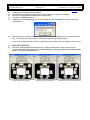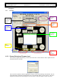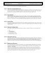
1
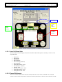
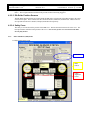
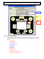
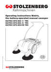
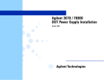
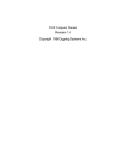
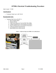
Docking Troubleshooting Tool Guide.doc
Document Number: N/A
Revision: wk 3
Page 1 of 14
Last Printed on: 02/19/04 @ 3:45 PM
FLEX SYSTEM DOCKING CONTROL
TROUBLESHOOTING TOOL
Docking Troubleshooting Tool Guide.doc
Document Number: N/A
Revision: wk 3
Page 2 of 14
Last Printed on: 02/19/04 @ 3:45 PM
1
Table of Contents
1
TABLE OF CONTENTS ............................................................................................................................................... 2
2
OVERVIEW.................................................................................................................................................................... 3
2.1
2.2
2.3
3
DOCUMENT OBJECTIVES....................................................................................ERROR! BOOKMARK NOT DEFINED.
REVISION HISTORY .................................................................................................................................................... 4
GLOSSARY ................................................................................................................................................................. 5
TEST PROCESSES (BACK)......................................................................................................................................... 6
Docking Troubleshooting Tool Guide.doc
Document Number: N/A
Revision: wk 3
2
Page 3 of 14
Last Printed on: 02/19/04 @ 3:45 PM
Overview
The FLEX Testhead Interface contains both docking mechanics and docking controls. The
interface mechanics has two separate sets of mechanisms that will be used for a complete docking
solution. The two mechanisms include the docking Outer Pull-Down modules (OPD module), and
the DIB (Device Interface Board) Inner Pull-Down (IPD). The control portion of the interface,
unlike the Tiger system’s, is completely independent to the manipulator.
IPD
Fences
OPDs
PHSB
Motor
Outer Ring
IPD
Testhead
Backplane
Figure 1
The IPD mechanism will be used to secure the DIB to the Testhead during production test and
customer test. This is achieved by the movement of four synchronized rollers (refer to Figure 1
above). The rollers are linked to a chain, which are moved by the motor. To ensure the chain is
positioned along the outer ring and all the gear wheels are engaged a spring tensioner is present
(Located next to the motor. Refer to Figure 2).
The OPD modules are similar to the Catalyst K-Dock modules. They are pneumatic activated by
solenoid valves mounted to the outer ring. This is actual control is provided by the controller
board. The control board will send signals to the solenoid valves resulting in the switching the
airflow to the different ports of the OPD units.
Docking Troubleshooting Tool Guide.doc
Document Number: N/A
Revision: wk 3
Page 4 of 14
Last Printed on: 02/19/04 @ 3:45 PM
Spring Tentioner
Motor
Solenoid
OPD
Chain
Figure 2
The control consists of one unit, the controller board. The controller will be used to detect the
status of the sensors as well as the control the motor and solenoid for IPD and OPD respectively.
The controller also contains control code to ensure the docking sequences occur properly.
2.1 Revision History
Date
01-23-04
Author
Steve Ford
Description of Change
Created
Docking Troubleshooting Tool Guide.doc
Document Number: N/A
Revision: wk 3
2.2
Page 5 of 14
Last Printed on: 02/19/04 @ 3:45 PM
Glossary
CV
DIB
DIB Clamped
DIB Neutral
DIB Released
Drive Clutch
Eng
Fences
IPD
K-Dock
OPD
OPD Extended
OPD Latched
OPD Retracted
Outer
Ring/Interface
Plate
PHSB (Pogo
Header Support
Beam)
Customer Verification similar to PV, but not as thorough
Device Interface Board
DIB position where the DIB is secured to the interface, roller are located in
the outer position
DIB install position where the IPD rollers are located in the middle range
position
DIB position where the RF connector forceses are released, rollers are located
in the inner position
Clutch used to not allow excessive force to be applied to chain by the motor
Engineer
Device used to align Interface cables to DIB
Inner Pull Down (also known as DIB pull down)
Catalyst version of an Outer pull down module
Outer Pull Down unit that mounts a peripheral to the testhead
Stage where the OPD pin is elongated to accept the groove module
Stage where the OPD pin locks the groove module to the testhead
Stage where the OPD pin pulls the groove module down
Describes the plate in which all mechanics and boards mount
Device used to mount interface cables and align the interface assembly
Docking Troubleshooting Tool Guide.doc
Document Number: N/A
Revision: wk 3
3
LAUNCHING TOOL
Page 6 of 14
Last Printed on: 02/19/04 @ 3:45 PM
(back)
3.1
3.2
3.3
3.4
3.5
UnZip the sock on the left top of the testhead.
The Hookup serial cable from testhead sock to either serial port A or B on tester computer.
Browse to C:\Program Files\Teradyne\IG-XL\<version>\bin
Search for SystemDockingGUI.exe.
Double click on SystemDockingGUI.exe or select and hit enter (GUI will display error if not connected to
controller first).
3.6
Once the tool starts you may see an msgbox (shown above). This is prompting for you to select an interface
type. You should only see this if you are working with Teradyne or Engineering interfaces.
If you see this on Intest then there is either a communication issue or there is an issue reading the Gusset sensors.
4
4.1
TOOL DESCRIPTION
The tool is customized based on the interface type. Each type falls into three classes, these classes are
Teradyne Dock (866-764-00), Engineering Dock (866-660-00), and Intest Dock (866-661-00, and 866-662-00).
Below is an example of the three classes.
Teradyne Dock (866-764-00)
Engineering Dock (866-660-00)
Intest Dock (866-661-00, 866-662-00)
Docking Troubleshooting Tool Guide.doc
Document Number: N/A
Revision: wk 3
4.2
Page 7 of 14
Last Printed on: 02/19/04 @ 3:45 PM
There are Four systems to this tool. Controller, Inner Pull Down (IPD), Outer Pull Down (OPD), and
Manipulator.
4.2.1
Controller
Sensor
refresh and
firmware
load
Controller
ID and SW
info
Layout
View
Controller
Actions
State
Controller
fault log
Key
Switches
Rotation
and
Pressure
4.2.1.1 Sensor Refresh and Firmware Load
The tool doesn’t update automatically you will need to click on the “refresh” button in order to update the latest
information from the controller.
The tool also has included a method of updating the firmware located on the Docking Control Board. The tool
will launch the PIC downloader, which defaults to the version shipped with the version of IG-XL. This can be
changed by clicking browse and locating the version of software. This also defaults to COM 1, but can be
Docking Troubleshooting Tool Guide.doc
Document Number: N/A
Revision: wk 3
Page 8 of 14
Last Printed on: 02/19/04 @ 3:45 PM
changed based on the port that is connected. The baud rate should also be filled in automatically to 19200. If
this is not correct then just select it through the pulldown menu.
4.2.1.2 Controller ID and Software Info
There are two fields located on the tool that display the controller info. The first is the info centered at the top of
the black interface outline. This displays the HW rev and current firmware version label “SW”. The second is
located on the tool’s bottom left witch contains the control board serial number and date code.
4.2.1.3 Key Switches
There are two key switches located on the front of the interface. These two switches are maintenance and the
safety cover bypass. The maintenance mode switch is used often to reset controller faults and return the system
back to a default state. The safety cover bypass allows the user to operate the system without the presents of the
safety cover or TUV cover. The tool option button will fillin in the presents of the key being “ON” or enabled.
4.2.1.4 Layout View
The layout view allows the user to determine how they would like to display the interface items. The two modes
are DUT UP and DUT DOWN. This feature is meant to aid in troubleshooting and avoid confusion of left right
sensors mix-ups.
4.2.1.5 Controller Actions State
The Controller Actions State displays the state the controller is currently in. Below is a list of possible states.
•
•
•
•
•
Idol
Pressure Normal
Low Pressure - Error
Pressure Shut Off - Error
Disconnected Hose – Error
4.2.1.6 Controller Fault Log
The fault log contains a list of the faults the controller has encounter during operation. The faults are numbered
and listed earliest to latest. To aid in identifying the fault they are date and time stamped with a brief description
of the fault. The date and time does have a limitation where time the system is shutdown (main power) the
controller is not aware of. The result is the date and time maybe inaccurate if the system is off for multiple days.
4.2.1.7 Rotation and Pressure
The controller measures the rotation of the testhead, to prevent IPD undocking so DIB doesn’t fall on the floor.
The angle is represented in the tool, DUT UP is considered 0 degrees. This doesn’t represent direction, so you
will not see +/- indications.
The Pressure is read from the sensor in the support cabinet. This pressure is required to activate the cutoff
solenoid. The cutoff solenoid is on the output of the regulator, so this could read within the specified pressure,
but no air could be provided to the interface. NOTE: the controller counts the number of times the pressure
drops below the cutoff and locks the cutoff value if the pressure drops more than three times.
Docking Troubleshooting Tool Guide.doc
Document Number: N/A
Revision: wk 3
4.2.2
Page 9 of 14
Last Printed on: 02/19/04 @ 3:45 PM
Inner Pull Down (IPD) Items
IPD State
Corner
Dib
Sensors
Safety
Cover
Present
Dib Roller
Position
Sensors
4.2.2.1 Inner Pull Down State
The Inner Pull Down State displays the state the controller reads the IPD system is currently in. Below is a list
of possible states.
•
•
•
•
•
•
•
•
•
•
•
•
Dib Present
IPD Docking
IPD Docked
IPD Undocking
IPD Undocking (Push Off)
IPD Undocking
Missing Dib In Place - Error
Gravity Sensor - Interlock
Timeout - Error
IPD Motor Overcurrent - Error
Missing Dib In Place - Error
Missing Dib Present - Error
4.2.2.2 Corner Dib Sensors
There are 4 sensors mounted on the interface located in the area of each corners of the DIB. The corner dib
sensors are used to detect the presents of a dib and if the dib is pulled down. The terms used to describe if a DIB
Docking Troubleshooting Tool Guide.doc
Document Number: N/A
Revision: wk 3
Page 10 of 14
Last Printed on: 02/19/04 @ 3:45 PM
is placed on the testhead is “Dib Present”, and the term used to describe if a DIB is pulled down is “Dib In
Place”. The tool option button will fillin in the presents of that sensor being triggered.
4.2.2.3 Dib Roller Position Sensors
The Dib Roller Position Sensors are located under the IPD rollers on both sides of the IPD opening in the center
of the interface plate. These sensors have three locations Docked, UnDocked, and Released. Theses locations
are represented in the tool as Neutral, Clamped, and Push Off respectively.
4.2.2.4 Safety Cover
The safety cover item detects the presents of the DIB cover. This has been also known as the TUV cover. The
tool option button will fillin in the presents of the cover. Note in order for the cover to be detected the DIB
must be fully docked.
4.2.3
Outer Pull Down (OPD) Items
Terdadyne Dock OPD system
OPD State
OPM
Sensors
Coarse
Alignment
Sensor
Docking Troubleshooting Tool Guide.doc
Document Number: N/A
Revision: wk 3
Page 11 of 14
Last Printed on: 02/19/04 @ 3:45 PM
Intest Dock OPD System
OPD State
Gusset
Sensors
CAM
Sensor
4.2.3.1 Outer Pull Down State
The OPD State displays the state the controller reads the OPD system is currently in. Below is a list of possible
states. (Intest states only represented in RED, Teradyne states only represented in BLUE, Common states are in
BLACK)
•
•
•
•
•
•
•
•
•
•
•
•
•
•
Manual OPD State
Manual Docking
Manual Undocking
Coarse Alignment Present
OPD Latch Made
All OPD Latches Made
OPD Docked
OPD UnDocked
Gusset Made
All Gussets Made
Power Assist Dock
OPD Between States (gussets)
OPD Between States (no gussets) - Error
OPD Between States (gusset) - Error
Docking Troubleshooting Tool Guide.doc
Document Number: N/A
Revision: wk 3
Page 12 of 14
Last Printed on: 02/19/04 @ 3:45 PM
4.2.3.2 Outer Pulldown Modules Sensors / Gusset Sensors
The outer pulldown module sensors for Teradyne Docking interfaces and gusset sensors for Intest dock
interfaces are the same item except of the label. These detect the presents of the peripheral plate. The tool
option button will fillin in the presents of that sensor being triggered.
4.2.3.3 Coarse Alignment Sensor
The coarse alignment sensor is only contained on the Teradyne Dock interface. The sensor provides the ability
to detect if the peripheral is close to interface. The tool option button will fillin in the presents of that sensor
being triggered.
4.2.3.4 CAM Sensors
The CAM sensors are used to determine the state the Intest Dock. Due to the manual capability of the intest this
is important for the control to identify the state. Below is the sensor output verse docking state diagram.
CAM 1
CAM 2
UNDOCK
DOCK
Docking Troubleshooting Tool Guide.doc
Document Number: N/A
Revision: wk 3
4.2.4
Page 13 of 14
Last Printed on: 02/19/04 @ 3:45 PM
Manipulator
Z Power
and Speed
Z Motion
Interlocks
Z Motor
State
4.2.4.1 Z Motor State
The Z Motor State displays the state the controller reads the Z motion system is currently in. Below is a list of
possible states.
•
•
•
•
•
•
•
•
Pwr Off - Idol
Pwr On - Idol
Slow Up
Slow Down
Pwr On - Idol
Fast Up
Fast Down
Z Motor Fault – Error
4.2.4.2 Z Power and Speeds
The Z power and Speeds show the user what state the Z motion power and speed the system is currently at.
There is two speeds to the interface High or FAST and low or SLOW. The tool option button will fillin to
indicate the current mode. Another feature of this tool in regards to the manipulator is the ability to click ON or
OFF the power and change the controller mode.
Docking Troubleshooting Tool Guide.doc
Document Number: N/A
Revision: wk 3
Page 14 of 14
Last Printed on: 02/19/04 @ 3:45 PM
4.2.4.3 Z Motor Interlocks
The Z Motor system has three features of fault detection. These features are limit switch UP, limit switch
DOWN, and Motor Fault, represented by “UP”, “DWN”, and “Motor” on the tool user interface. A fault is
indicated by the filling in of the option button.