1
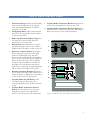
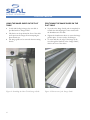
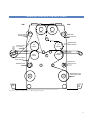
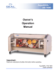
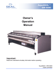
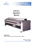
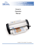
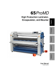
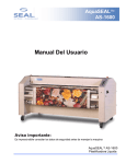
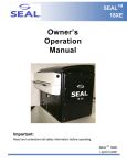
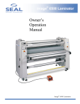
Image ® 6500 XT Laminator Owner’s Operation Manual Addendum for 6500 XT Please read the SEAL® Image® 6500 Owner’s Manual for the basic operating procedures before using this addendum. 2 TABLE OF CONTENTS TABLE OF CONTENTS........................................................................................................................................................................... 3 INTRODUCTION ..................................................................................................................................................................................... 4 6500 XT BACK CONTROL PANEL....................................................................................................................................................... 5 FEEDING IMAGES................................................................................................................................................................................. 6 ONE PASS DRY TRANSFER AND OVERLAMINATE.................................................................................................................... 7 TRANSFER PROCESS CONTROL CHART.......................................................................................................................................... 9 6500 XT PROCESS CONTROL CHART................................................................................................................................................. 10 6500 XT TECHNICAL SPECIFICATIONS ........................................................................................................................................... 11 3 INTRODUCTION The purpose of this addendum is to outline the differences in operation and features of the SEAL Image 6500 XT laminator in addition to the SEAL Image 6500 laminator model. IMPORTANT! All information regarding WARNINGS and Safety Information contained in the SEAL Image 6500 Owner’s Manual is valid for the operation of the SEAL Image 6500 XT laminator. 6500 XT Additional Features: • Higher temperature and transfer capabilities (300°F/149°C) Main Roller Temperature • Third heated top rear roller for additional processing capabilities (250°F/120°C) Top Rear Roller Temperature • Rear Table Image Guide • Single pass over-lamination and transfer processing • Faster Laminating and Mounting Speed 15 fpm (4.6 mpm) • Outfeed Slitter System 4 6500 XT BACK CONTROL PAN EL 1. Air Pressure Gauge: Indicates the PSI reading for the downward pressure of the top pull roller. The standard setting for the normal operation is 35-55 PSI. 2. Air Regulator Knob: Adjusts the downward pressure of the top pull roller. Turn clockwise to increase the pressure. 3. Roller Up/Down Switch (Rear, Top): Press the switch up to raise the roller. Press the switch down to lower the roller. 4. Reset Button: Press this button to reset the material total usage counter to zero. Totalizer Display must be showing to be able to zero out. 5. Ratemeter /Totalizer Button: Pressing this button will toggle between the roller speed readout or total material usage. Press this button to track and display the total number of feet or meters run in a given period, which can help to monitor film usage. The total will be stored even after the laminator is turned off, and adds to the total whenever the bottom main roller is turning. The corresponding LED will be lit when the Totalizer is being used. 6. Ratemeter/Totalizer Readout: Displays the rate of speed of the main rollers in either feet or meters per minute, or displays the total number of feet or meters run in a given period. 7. Top Rear Roller On/Off Button: Turns On/Off the top rear roller heater. The corresponding LED will be lit when the heater is ON. 8. Top Rear Roller Temperature Increase Button: Press this button once to view the temperature set point. Press and hold the button to raise the top rear roller temperature. 9. Top Rear Roller Temperature Readout: Displays both the set and actual temperature of the top rear roller. 10. Top Rear Roller Temperature Decrease Button: Press this button once to view the set point. Press and hold the button to lower the top rear roller temperature. 1 80 2 3 60 40 20 0 100 120 140 160 4 5 6 7 8 9 10 Figure 1. 6500 XT Top Heat Back Control Panel 5 FEEDING IMAGES USING THE IMAGE GUIDE ON THE FLAT TABLE POSITIONING THE IMAGE GUIDE ON THE FLAT TABLE • To aid with feeding in images, the rear table is provided with an “Image Guide”. • • This device can be positioned in front of the roller and it prevents the images from interrupting the photoelectric eyes. To position the Image Guide, push it completely in towards the roller aligning the outer notches with the thumbscrews in the table. • Tighten the thumbscrews down to secure the image guide in place. You are ready to feed images. • The image guide can be removed when mounting boards. • To assist with this, the edge of the image can be seen through the windows in the “Image Guide”, which is in front of the rollers. Figure 2. Installing the Rear Table Image Guide 6 Figure 3. Placement of the Image Guide ONE PASS DRY TRANSFER AND OVERLAMINATE The One-Pass Dry Transfer process involves transferring an image onto a flexible Marking film and applying an over laminate to the image transfer. Applying the over laminate to the top of the image transfer increases the longevity of your image transfer and allows for outdoor applications. Some types of Transfer Media do not require an over-laminate; please refer to the product literature for recommendations. • Rear of the Laminator: pull the overlapped film through the main roller nip, over the first chill idler and under the second. • Pull the film through the pull rollers making sure the film is tracking centered through all rollers evenly. • Pull the film down and tape it securely to a cardboard core placed over the bottom rear take-up shaft. This will automatically wind up the finished product. Set-Up for the Transfer Process NOTE: Heat-up time is approximately 45 minutes. NOTE: Check if the film widths of the lower and upper web are the same! • Refer to the Process Control chart for settings and set the laminator up accordingly. • NOTE: the cooling tube is in the lower position. • IMPORTANT! The main roller should be down and turning to prevent uneven hot spots on the roller. A stationary heated roller will develop concentrated heat in one area, which will damage the roller. TRANSFER MEDIA: Load and center on the front top unwind shaft with the (toners) facing out and the unwind brake tension released. • Adjust and align the roll of Transfer Media to the roll of Marking film. • Pass a length of Transfer Media behind the front top idler, and pull the media forward, again allowing extra to overlap for hand protection from the heated top roller and feed into the nip area. • Rear of the Laminator: pull the overlapped media through the main roller nip, over the first chill idler and under the second. • Pull the Transfer Media upward, around the rear, top unwind shaft, over the roll of transfer media on the front top unwind shaft and tape it securely to a cardboard core placed over the front top take-up shaft. This will automatically wind-up the media paper after toners have been removed. • PRESSURE-SENSITIVE OVERLAMINATE: Load and center the over-laminate on the rear roll easel shaft aligning it with the finished output. • Pull the overlaminate upward and tape the release liner to a cardboard core placed over the rear top take-up shaft. • Raise the top rear roller and pass the overlaminate over the back of the roller and into the nip. • Pull the overlaminate down to the lower rear takeup shaft and adhere over the Marking film. • Adjust the web tensions on the unwind and take-up shafts according to the recommended settings. • • Once the bottom roller has reached about 140° F (60°C), raise the top roller and every 5 to 10 minutes hand spin the top roller using a soft cloth for skin protection until it reaches the required temperature. CAUTION! The top roller is very hot; use care when reaching over or touching the roller to prevent burns. Once the laminator reaches correct operating temperature follow the webbing procedure. Refer to the Webbing Diagram on the corresponding page. Webbing for the Transfer Process • MARKING FILM (VINYL): Load and center on the front bottom unwind shaft with the toner receiving side (shiny side) facing out and the unwind brake tension released. • Pull a length of film off the bottom unwind shaft and pass it behind the front bottom idler. • Pull the film forward to feed into the main roller nip. To protect your hands from the heat of the rollers, pull an additional 2 to 3 feet of film, overlapping the film over your hands and feed into the nip area. 7 TRANSFER PROCESS CONTROL CHART MEDIA: Electrostatic Transfer Webbing Settings FILMS: Web Tension Marking Film: Light to Medium -- -- -- Front Bottom Unwind Shaft: Marking Film (Vinyl) Web Tension Transfer Media: Heavy Web Tension Over-laminate: None to Light _____ Front Top Unwind Shaft: Transfer Media Chill Idlers: Over 1st / Under 2nd . . . . . Roll Easel Shaft: Over-laminate (Optional) Front Shim Wheel Settings: -1/16 (-2mm) Rear Shim Wheel Settings: -1/16 (-2mm) TRANSFER PROCESS SETTINGS: Front Control Panel Top Roller Temp.: 300°F (149°C) Bottom Roller Temp.: 120°F (49°C) Main Roller Pressure: 85-90 PSI Cooling Fan: ON, Under Chill Idlers Back Control Panels Top Rear Roller Temp.: Over-laminate Determined Pull Rollers: Down Pull Roller Pressure: 35-40 PSI Pull Clutch Tension: 40-60 PSI IMPORTANT! We recommend maintaining these temperatures during long runs to ensure the highest-quality output. Do not allow the top roller temperature to drop below 290° F (143°C). Allow the bottom roller to cool down if the temperature exceeds 160° F (71°C) before continuing the process. NOTE: The speed can be adjusted (slower or faster) depending on at what speed you have the best total transfer of the toner into the film. NOTE: Low temperature heat assist (120° F/49°C) on the Over-laminate will reduce silvering on the final output. NOTE: The clutch tension pressure should not exceed 40 psi. This will prevent excessive pull on the film, affecting the output. Motor Control Panels Motor Direction: Forward Motor Speed Setting: 1-10 fpm (.3-3.0 mpm) 8 NOTE: The settings are general recommendations. Refer to your media specific Product Literature for their recommended settings. NOTE: If you are not applying an over-laminate or prefer to do the transfer as a two-step process (applying the over-laminate in a 2nd pass) the tonerremoved transfer media can be taken up on the rear, top take-up shaft. TRANSFER PROCESS CONTROL CHART Shim Wheel Rear Over-laminate Release Liner Rear Top Wind-up Front Shim Wheel Rear Top Supply Shaft Front Top Supply Shaft Front Top Wind-up Media after toners removed Top Idler Rear Roll Easel Pressure-sensitive Over-laminate Transfer Media Toners facing in Top Main Roller Top Pull Roller Chill Idler Rear Table Removed Bottom Pull Roller Print Guide Front Table Chill Idler Bottom Main Roller Fan Tube Pressure-sensitive Over-laminate Finished Product Rear Bottom Wind-up Bott Idler Rear Bottom Supply Shaft Covered Foot Switch Bott Idler X Front Bottom Wind-up Front Bottom Supply Shaft Remove front bottom wind-up Marking Film (Vinyl) Toner receiving side Covered Foot Switch Figure 4. Dry Transfer Process Webbing Diagram 9 6500 XT PROCESS CONTROL CHART Process: _________________________________ Motor Control Panel Settings Application Use: ___________________________ Motor Direction: Forward _______/ Reverse _______ Top Unwind Shaft:__________________________ Motor Speed Setting: ________________________ Bottom Unwind Shaft: _______________________ Webbing Settings Front Control Panel Settings Top Roller Temp: __________________________ Bottom Roller Temp: ________________________ Main Roller Pressure: ________________________ Cooling Fan: On ___ Off ___ Above ____ Below ____ Chill Idlers: [Over/Under] 1st / 2nd ______________ Web Tension Top Unwind Shaft: Light ________/ Med. _________/ Heavy _________ Web Tension Bottom Unwind Shaft: Light ________/ Med. _________/ Heavy _________ Back Control Panel Settings Shim Wheel Settings: Front ________/ Rear________ Top Pull Roller Temp: _______________________ Images: Sheet Fed ___________/ Roll Easel _______ Pull Rollers: Up ___________/ Down ___________ Shim Wheel Rear Pull Roller Pressure: ________________________ Pull Clutch Tension: ________________________ Rear Top Wind-up Front Shim Wheel Rear Top Supply Shaft Front Top Supply Shaft Front Top Wind-up Top Idler NOTE: We recommend that you make a photocopy of this page. With each successfully run application, record the process and settings and a diagram of the webbing procedure. Keep the record so the application can be repeated at a later date. HINT: If a standard image is made available for each new process then sales materials and samples can be developed for reference. Top Pull Roller Rear Roll Easel Top Main Roller Front Roll Easel Fan Tube Chill Idler Rear Table Bottom Pull Roller Rear Bottom Wind-up Rear Bottom Supply Shaft Chill Idler Print Guide Front Table Bottom Main Roller Fan Tube Bott Idler Bott Idler Front Bottom Wind-up Front Bottom Supply Shaft Covered Foot Switch Covered Foot Switch Figure 5. Blank Webbing Diagram 10 6500 XT TECHNICAL SPECIFICATIONS Mechanical Dimensions (H x W x D) 56” x 85” x 57” (1423 mm x 2159 mm x 1448 mm) Net Weight 1,710 lbs. (775 kg) Shipping Weight 2,260 lbs. (1025 kg) Roller Construction Four high release silicone-covered rollers Process Max. Working Width 61” maximum (1550 mm) Max. Roller Speed 15 ft/min. (4.6 m/min.) Max. Roller Opening 1.75” (44 mm) Maximum Main Roller Force 42.8 lbs./in. (7.5 N/mm) @ 90 PSI Maximum Substrate Thickness 1” (25.4 mm) Nip Settings 0, 1/16, 1/8, 3/16, 1/4, 3/8, 1/2, 3/4, 1 and –1/16” (0, 2, 3, 5, 6, 10, 13, 19, 25 and -2 mm) Max. Main Roller Temperature 300°F (149°C) Max. Rear Roller Temperature 250°F (120°C) Core Inner Diameter 3” (76 mm) Electrical Electrical Requirements Single Phase Version 200-240 Vac, 50/60 Hz, 48A, 2/G Three Phase Version 230-400 Vac, 50/60 Hz, 22A, 3N/PE Maximum Power consumption 11,000 watts NOTE: Airborne Noise Less than 70DB(A) Order Codes SEAL ® Image® 6500 XT Single phase 63040 SEAL ® Image® 6500 XT International Three phase 63041 SEAL ® Image® 6500 XT International Single phase 63042 11 SEAL ® CONTACT INFORMATION SEAL Brands Technical Service SEAL Brands Technical Service – Europe and Asia Pacific (For technical assistance & service) (For technical assistance & service) Tel: 1-800-486-6502 For UK: Tel: +44 1268 722 400 Fax: 1-800-966-4554 Fax: +44 1268 729 442 or +44 870 125 5798 For NL: Tel: +31 572 345 500 Fax: +31 572 345 501 SEAL Brands Customer Service SEAL Brands Customer Service – Europe and Asia Pacific (For information and placing orders) (For information and placing orders) Tel: 1-800-257-7325 Tel: +31 572 345 500 Fax: 1-800-966-4554 Fax: +31 572 345 501 Note: SEAL Graphics recommends that your main power be installed by a licensed electrician in accordance with electrical codes in your area. Specifications subject to change without notice. Seal Graphics Americas Corporation 7091 Troy Hill Drive Elkridge, MD 21075 Tel: 410-379-5400 Fax: 410-579-8960 Seal Graphics Canada 1601 Matheson Blvd. E. Unit #4 Mississauga, Ontario Canada, L4W 1H9 Tel: 905-212-9232 Fax: 905-212-9313 Seal Graphics U.K. Ltd Unit 1, 1 Watkins Close Burnt Mills Industrial Estate Basildon, Essex SS13 1BJ United Kingdom Tel: +44 1268 722 400 Fax: +44 1268 729 442 www.sealbrands.com © 2002 SEAL Graphics SEAL and Image are registered trademarks of SEAL Graphics Part #OM6500XT-E Rev. B (11/02) 12 Seal Graphics Europe BV Kanaaldijk O.Z.3 P.O. Box 29, 8100 AA Raalte The Netherlands Tel: +31 572 345 500 Fax: +31 572 345 501 Seal Graphics Pacific Limited Unit A, 13th Floor, Block 1 Leader Industrial Centre Tsuen Wan, New Territories, Hong Kong Tel: +852 2407 3738 Fax: +852 2408 0973