1
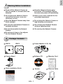
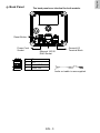
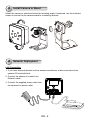
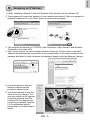
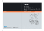
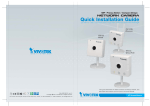
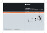
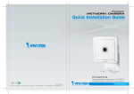
English
Warning Before Installation
Power off the Network Camera as
soon as smoke or unusual odors are
detected.
Keep the Network Camera away
from water. If the Network Camera
becomes wet, power off immediately.
Do not place the Network Camera
around heat sources, such as a
television or oven.
Refer to your user’s manual for the
operating temperature.
Keep the Network Camera away from
direct sunlight.
Do not place the Network Camera in
high humidity environments.
Do not place the Network Camera on
unsteady surfaces.
Do not touch the Network Camera
during a lightning storm.
Do not disassemble the Network
Camera.
Do not drop the Network Camera.
Do not insert sharp or tiny objects
into the Network Camera.
1
Package Contents
IP8130
IP8131
Power Adaptor (+12V, 1A)
Camera Stand
Software CD
Warranty Card
500024701G
Quick Installation Guide
Screws
EN - 1
Ethernet Cable
2
Physical Description
Front Panel
IP8130
Status LED
Lens
Microphone
MicroSD/SDHC/
SDXC Card Slot
IP8131
Lens
Status LED
IR LEDs
Microphone
Item
LED status
Description
1
Steady Red
Red LED off
Blink Green every 1 sec.
Steady Red
Power on and system boot
Power off
Network connected
Network failed
Blink Green, RED, and Orange
intermittently
Blink Orange every 0.15 sec.
Restoring default
2
3
4
EN - 2
The back panels are identical for both models.
Reset Button
Power Cord
Socket
1
2
3
4
Ethernet 10/100
RJ45 Socket
General I/O
Terminal Block
DIDI+
Audio GND
Audio Out
Audio out cable is user-supplied.
EN - 3
English
Back Panel
3
Install Camera to Stand
Attach the camera to stand and orient the shooting angle. If preferred, use the included
screws to secure the the camera stand to a mounting surface.
4
Network Deployment
LAN Connection
1. If you have external devices such as sensors and alarms, make connections from
general I/O terminal block.
2. Connect the camera to a switch via
Ethernet cable.
3. Connect the supplied power cable from
the camera to a power outlet.
POWER
EN - 4
COLLISION
1
2
3
4
5
LINK
RECEIVE
PARTITION
English
5
Assigning an IP Address
1. Install “Installation Wizard 2” from the Software Utility directory on the software CD.
2. The program will conduct an analysis of your network environment. After your network is
analyzed, please click on the “Next” button to continue the program.
Installation
Wizard 2
3. The program will search for VIVOTEK Video Receivers, Video Servers, and Network
Cameras on the same LAN.
4. After a brief search, the main installer window will pop up. Double-click on the MAC
address that matches the one printed on the camera label or the serial number on the
package box label to open a browser management session with the Network Camera.
IP8130
MAC:0002D132C353
00-02-D1-32-C3-53
192.168.5.151
IP8130
0002D132C353
This device complies with part 15 of the FCC rules. Operation is subject to the following two conditions:
(1)This device may not cause harmful interference, and
(2) this device must accept any interference received, including interference that may cause undesired operation.
Pat. 6,930,709
5. A browser session with the
Network Camera should
prompt as shown below.
6. You should be able to see live
video from your camera. You
may also install the 32-channel
recording software from the
software CD in a deployment
consisting of multiple cameras.
For its installation details,
please refer to its related documents.
2012/11/05 01:50:28
EN - 5