1
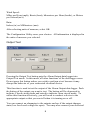
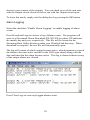
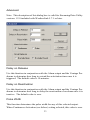
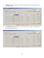
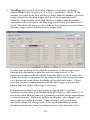
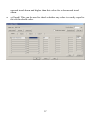
WeatherLink® for Alarm Output
Addendum
Introduction
This Streaming Data Logger is designed to provide an electrical interface
between a Vantage Pro™ or Vantage Pro2™ weather station console or
Weather Envoy™ and an electrical device. You may set a series of
thresholds for various parameters that will trigger if any of them are met (OR
condition), all of them are met (AND condition), one and only one is met
(XOR condition). You may also test whether a parameter is within (between
condition) or outside of (not between condition) a certain range, or changing
at a certain rate (trending), or how far apart (or close) two like parameters are
from each other. Finally, you may also test various parameters to see if they
are reporting a valid number. This can be used to signal a bad data
connection or malfunctioning sensor.
This product also contains the functionality of the WeatherLink for Vantage
Pro Serial version. Please consult the WeatherLink for Vantage Pro Getting
Started Guide and on-line Help files for information on the use of the
WeatherLink program (including its hardware requirements and typical
installation), package contents, and optional accessories for this product.
If you plan to install this product in a Vantage Pro or Vantage Pro2 console,
use the notch in the battery door located adjacent to where the PC connector
protrudes and above the AC power connector to bring out the Connector
Block wire.
If you plan to install this product in a Weather Envoy, it is recommended that
you knock out the left-most tab with the Weather Envoy’s PC connector
facing you and loop the Connector Block wire around the datalogger
connector to the Weather Envoy and bring it out where this tab was removed.
1
Hardware Installation and Requirements
In addition to the requirements for WeatherLink, the Alarm Output capability
of this product has the following additional hardware requirements.
•
One Free Serial Port or One Free USB port with the Serial to USB
adapter (Part # 8434) connected to a Windows PC.
• Computer running any version of Windows with at least 3 MB free
of RAM and 512 KB free of hard disk space.
• Small Slotted Screwdriver
• (Optional) Relays: You may need to obtain relays in order to switch
equipment at voltages higher than 28 Volts or power levels above 10
Watts. Not available from Davis Instruments.
Note: Due to its normal operation, this product will draw more current from
the console and Envoy than in typical use. Davis recommends you use the
power adapter provided with your product if you are concerned about battery
life. Additionally, you can optimize battery life by setting your outputs to
normally open, particularly those you do not plan to use.
Software Installation and Setup
Installing the Software
Follow the installation instructions for WeatherLink. This will also install
the configuration software. The install file contains this program as well as
WeatherLink if you ever need to install the program manually.
Running the Configuration Software
To run the configuration software, double-click on the Streaming Data Utility
icon in the Streaming Data Utility directory of the WeatherLink directory or
select the Streaming Data Utility from the Start Menu under the WeatherLink
directory.
Finding the Correct Serial Port
The configuration software includes a procedure for locating the serial port to
which your streaming data logger is connected or determining whether that
serial port is working.
2
Use the Serial Port Settings dialog box to select the correct COM port and
baud rate to communicate to the streaming data logger. The correct baud rate
will be the one set in your Vantage console, and in WeatherLink. The
default value is 19200 baud. You may manually set the COM port setting or
use the Auto Detect button to automatically find where your streaming data
logger is connected.
Note: If you have more than one streaming data logger connected to your
system, it is highly recommended that you manually set the Com Port and
Baud Rate.
3
Logger Type
The software indicates the logger type and firmware revision level of the
streaming data logger in the logger type box.
4
Time Out Period
The Alarm Output data logger will always hold an attached device in the
appropriate state (On or Off) as dictated by the alarm settings. However, the
Alarm Output data logger utilizes a time-out period for ceasing checking the
alarm conditions whenever software attempts to communicate to the logger.
The default and minimum setting is 5 seconds. Once the time out period
ends, the data logger will again check the alarm conditions to determine
whether to leave an output open or closed. You may adjust this value if you
want the alarm checking functions to resume later after communicating to the
logger using WeatherLink or the Streaming Data Utility.
Press OK to configure this setting in the dialog box. Press Cancel to exit the
dialog box and preserve the original settings.
Note: Once communications to WeatherLink are initiated and successful, the
streaming data logger will be unable to communicate with the Streaming
Data Utility until the Time Out Period expires. If you need to communicate
to the logger with both the Streaming Data Utility and WeatherLink, you
should communicate using the Streaming Data Utility first.
5
Station Configure
Before setting alarms, use this function to indicate what sensors you have
with your Vantage Pro or Vantage Pro2 system. The Configuration Utility
uses your choices to determine what parameters to show in the list. Note that
you can only enter this dialog box when no alarms are set. This prevents a
user from hiding a parameter that is set as an alarm condition.
Selecting Vantage Pro Plus automatically checks the Solar Radiation and UV
check boxes. You can also check them separately.
The Leaf Wetness, Soil Moisture, Leaf Temperature, and Soil Temperature
selections refer to the sensors on the Leaf & Soil Moisture Temperature
Station or Soil Moisture/Temperature Station. Temp 1, Temp 2, Humidity 1,
Humidity 2 refer to the sensors on the Wireless Temperature or Wireless
Temperature/Humidity Stations. Indicate the sensor by selecting the number
that corresponds to the transmitter ID on your Wireless Temperature or
6
Temperature/Humidity Station. Please note that the Alarm Output data
logger makes no distinction between Vantage Pro and Vantage Pro2.
The temperature and humidity readings are numbered according to their
station transmitter ID. So, for example, if you have an ISS on Transmitter ID
# 1 and a Temperature/Humidity Station on ID # 4, and a Temperature
Station on ID # 2, you would check the following dialog boxes in the
example shown below. There is no need to indicate your ISS Temperature
and Humidity sensors because they always appear under “Outside
Temperature” and “Outside Humidity” in the parameter pick list.
7
Units
Next, select the units of measure in which data is displayed within this
Configuration Utility software. Choosing units of measure in this software
does not affect the units of measure displayed on the console, which may be
changed independently of this software.
You may select from the following settings:
Temperature:
Fahrenheit (°F) or Celsius (°C)
Note: Wind chill, dewpoint, degree-days, and temperature indexes are all
displayed in the same unit of measure as temperature.
Barometer:
Inches of Hg (in), Millimeters of Hg (mm), Millibars (mb), or HectoPascals
(hPa).
8
Wind Speed:
Miles per Hour (mph), Knots (knot), kilometers per Hour (km/hr), or Meters
per Second (m/s)
Rain:
Inches (in) or Millimeters (mm)
After selecting units of measure, select OK.
The Configuration Utility saves your choices. All information is displayed in
the units of measure you selected.
Output Test
Pressing the Output Test button puts the Alarm Output data logger into
Output Test mode. In this mode, all other functions of the data logger cease.
Do not press this button unless you wish to perform a test because it may
disrupt the behavior of your connected electrical device.
This function is used to test the output of the Alarm Output data logger. Push
the button of the output you want to test. The button will be depressed to
indicate Closed circuit mode and raised to indicate Open circuit mode. To
utilize this function effectively, you will need to connect a device to the
appropriate output so that you can tell when it is turning on or off.
You can connect an ohmmeter to the outputs and see if the output changes
state (low for closed or high for open). You may also connect your electrical
9
device to one or more of the outputs. You can check to see if the unit runs
with the Output circuit closed or fails to run with the Output circuit open.
To leave this mode, simply exit the dialog box by pressing the OK button.
Alarm Logging
Select the checkbox “Enable Alarm Logging” to enable logging of alarm
events.
Press Download Logs to retrieve a log of alarm events. The program will
write to a file named Alarm Download XX-XX-XX.txt where XX indicates
the month, day and year, respectively. This file will be located in the
Streaming Data Utility directory under your WeatherLink directory. When
download is complete, the text file will automatically open.
The log will consist of which output became active, which parameters caused
the alarm to become active (useful for the AND type alarm) along with the
date and time that the alarm became active. This log is cleared whenever any
of the output alarms are cleared.
Press Clear Logs to erase any logged alarm events.
10
Advanced
Note: This description of this dialog box is valid for Streaming Data Utility
versions 1.2.0 included with WeatherLink 5.7.1 or later.
Delay on Release
Use this function in conjunction with the Alarm output and the Vantage Pro
alarms to determine how long to extend the activitation time once it is
triggered. The default value is 10 minutes.
Delay on Reactivation
Use this function in conjunction with the Alarm output and the Vantage Pro
alarms to determine how long to delay the reactivation of an alarm once it is
inactive. The default value is zero.
Pulse Width
This function determines the pulse width for any of this selected output.
When Continuous Activation (see below) setting selected, this value is zero.
11
In the case of consecutive pulses, it also determines the time between pulses.
In most cases, there is no need to alter this value unless directed to do so by
the manufacturer of the electrical device you plan to connect to the Alarm
Output data logger.
Alarm Activation
This command determines whether an output for an activated alarm is
continuous throughout the activation time or a one time pulse. The default is
continuous activation. Pulsed relay oriented devices will require the onetime pulse.
Circuit Behavior
This command determines whether the circuit stays open or closed when no
alarms are active. The opposite behavior occurs for an active alarm
condition. Default is normally open. Choose normally open if you want the
Alarm Output data logger to leave an electrical device OFF unless an alarm
condition occurs. Choose normally closed if you want the Alarm Output data
logger to leave an electrical device ON unless an alarm condition occurs.
Normally open mode conserves console or Envoy battery power.
Default
Press this button to restore the data entries to their default values. You must
still hit OK to save the settings in the data logger.
Output
Select the appropriate tab (Output 1 – 4) to configure the alarm settings for
each output.
For each output, first select the first parameter you want to test. For the
Minus check type, you will need to select a second parameter after you select
the Minus check type.
12
Then, select what type of test condition you want to check it against:
•
A Greater Than or = or high alarm checks for greater than or equal to.
•
A Less Than or = or low alarm checks for less than or equal to.
13
•
A Between alarm checks to see if the current value is between the two
threshold values.
•
A Not Between alarm checks to see if the current value is not between
the two threshold values.
14
•
True or False check (Boolean). This is used for the Low Transmitter
and Repeater Battery Status parameters, which are not numeric. This
check type can also be used with the Bar Trend parameters.
15
•
Trending allows you to determine whether a particular variable is
approaching a value of concern. It is like a “predictive” alarm. If the
number you enter in the first edit box is lower than the number you enter
in the second box, the data logger will check for an upward trend.
Likewise, if the number in the first edit box is higher than the number
you enter in the second box, the data logger will check for a downward
trend. The third edit box is used to indicate the maximum period of time
that may elapse before this alarm is no longer valid.
For this type of alarm to be valid, the parameter of interest must pass
through both thresholds within the specified time period. If the
parameter is between the thresholds when the alarm is set, or above the
higher threshold for an upward trend alarm or below the lower threshold
for a downward trend alarm, the alarm will not become active. Please
note that frequent communication with the data logger will cause the
timing function of this alarm type to run long.
For guidance on how to use this alarm, it may be best to consult
historical weather data from WeatherLink plot data (or other sources) to
determine what kind of behavior a parameter exhibits before approaching
a value of concern. Make note of how quickly the value changes over
time before it reaches that value. These changes will govern your
threshold values and time period. Your second threshold probably
should not match this value, but rather be lower than this value for a
16
upward trend alarm and higher than this value for a downward trend
alarm.
•
= (Equal) This can be used to check whether any value is exactly equal to
the set threshold value.
17
•
Minus or “Difference” alarm allows you to compare the difference
between two like variables. For this check type, the two variables must
be measured in the same units of measure in order to be compared. If
this check type is selected, the software will use the parameter pick list
on the row below for the second of the two like variables to indicate.
Enter a positive difference you want to compare in the available edit box
on the second of the two lines (this software will only allow you to enter
a positive difference). Select whether you want to check a “Greater Than
or =” or “Less Than or =” difference. Make sure the equation you create
results in the check that you want. Some examples are provided below:
1. A user wants to activate a fan to bring in cooler outside air to
passively cool their house. This affect only works if the temperature
outside is 5°F lower than the inside temperatures. Additionally, you
don’t want to cool your house if the inside temperature is 70°F or
lower. This can be expressed as:
“IF Inside Temperature Minus Outside Temperature IS Greater Than
or = 5.0°F. AND Inside Temperature IS Greater Than or = 70°F
DONE.”
2. A user wants to activate their sprinkler system when the Daily ET
exceeds the Daily Rainfall by 0.05”:
“IF Daily ET Minus Daily Rain IS Greater Than or = 0.05 DONE”.
3. A user wants to activate environmental controls whenever the
temperature outside differs from the inside temperature by 20°F or
more. Whether it is hotter or colder outside does not matter, but if
18
the inside temperature is between 68°F and 72°F, there is no need to
alter the inside temperature:
“IF Outside Temperature Minus Inside Temperature IS Greater Than
or = 20.0°F OR Inside Temperature Minus Outside Temperature IS
Greater Than or = 20.0°F AND Inside Temperature IS Between 68°F
& 72°F DONE”.
•
Missing: This is used to check whether a given parameter is missing or
invalid.
19
Finally, choose your Logical Grouping (whether you want to test this
condition along with any other conditions).
Choose DONE if this is the only condition you want to check. Choose OR if
you want this condition or any of the other conditions you set to trigger an
alarm. Choose AND if you require this condition and all of the other
conditions you set be present to trigger an alarm. Choose XOR if you want
an alarm to trigger if only one of the conditions you are checking becomes
valid. You may use this selection for the Minus check type except that every
use of the Minus check type takes up two lines.
Press OK to save all your Alarm Output settings (except the Advanced
settings), Cancel to preserve your previous settings. Please note that the
Configuration Utility only makes changes to any settings that are different
from the previous settings. Thus, you may notice the program takes longer
times than others to set values.
Note on parameters:
• Barometer Trend parameters: Use the True check type for this
parameter. Each of the four barometer trends (rising rapidly, rising
slowly, steady, falling slowly, and falling rapidly) when used will
alarm separately. If you wish to trigger an alarm if the barometer is
falling slowly or rapidly you will need to select the first parameter on
one line and then the second parameter on the second line and link
them together using the OR grouping type.
20
•
•
•
•
Wind Chill and Heat Index formulas the streaming data logger uses
are the same as the May 2005 revision of the Vantage Pro2 console
firmware. Wind Chill uses the 10-minute average wind for
calculation. Your console must be powered for at least 10 minutes to
utilize a valid wind chill value.
Dewpoint formula is also the same as what the Vantage Pro and
Vantage Pro2 console uses, but this has not changed from the
original firmware version to present.
Time: Time is entered in 24-hour format. For example, 10 pm is
entered as 22:00. Enter am values of 1 am or later as they are, enter
pm values of 1 pm or later by adding 12 to the hour. 12 am values
should be entered as 00:00. When using the between and notbetween check types, the Alarm Output data logger is intelligent
enough to handle the midnight rollover. For example, if you set “IF
Time is between 22:00 and 02:00”, the alarm will active when the
time of day is between 10 pm and 2 am including 11 pm, Midnight,
and 1 am and any times in between. Reversing the entries will cause
the alarm to be active nearly all day excluding the period around
midnight.
Wind Direction: When using the between and not-between check
types, the Alarm Output data logger is intelligent enough to handle
the North rollover. For example, if you set “IF Wind Direction is
between 350° and 10°”, the alarm will active when the wind
direction is between 350° and 10° including 355°, 0°, and 5° and any
directions in between. Reversing the entries will cause the alarm to
be active for most wind directions excluding those around north.
Consult Application Note 28 for more detailed information on how derived
parameters are calculated. This could be found at the Davis Instruments
website:
http://www.davisnet.com/product_documents/weather/app_notes/apnote_28.
pdf .
Clear
Press the Clear button to clear the alarms for this output only. This function
clears both the dialog box entries and the settings in the datalogger. You
must press this button for each of the individual outputs you want to clear.
21
Contact Specifications
The “contact” closure is provided by a photo-coupled MOS device. Because
it is a solid-state device, it is not subject to arcing and contact-welding as are
mechanical relays. However, since it is a solid-state device, it will be
damaged by operation beyond its ratings, which are:
Nominal Load Voltage: 28 V AC or 48 V DC, Maximum
Peak Voltage:
± 60 V, Maximum
Load Current:
± 1.8 A, continuous Maximum at 77°F (25°C),
derated to 0.7 A at 185°F (85°C)
ON Resistance:
0.12 Ohm, Maximum
Note: Upon power up (powering the console or Envoy), the datalogger will
briefly test all four outputs by closing the circuit (turning on the output). It is
recommended that you disconnect any equipment attached to the datalogger
outputs before rebooting the console or Envoy.
22
23
Product Number: 06544
Davis Instruments Part Number: 07395.219
WeatherLink for Alarm Output
Rev. C Addendum (2/5/07)
24