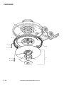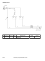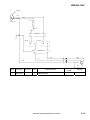
1
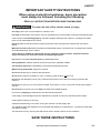
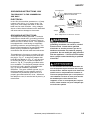
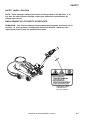
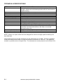
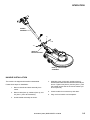
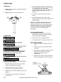
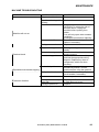
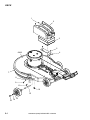
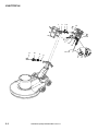
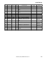
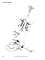
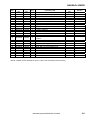
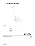
HIGH SPEED BURNISHER
MODELS:
LB2000I
LB2000IA UB2000F LB2000
10090200 10090210 10090620 10090190
Operating Instructions (ENG)
86309600-K
05/30/12
MACHINE DATA LOG/OVERVIEW
Model:
Date of Purchase:
Serial Number:
Sales Representative:
Address:
Phone Number:
OVERVIEW
The High Speed Burnisher is a mains powered, portable floor burnisher intended for commercial
use. The appliance can be fitted with a variety of pads to perform various floor care functions. The
appliance employs active dust control, and automatically adjusted pad pressure.
Warranty Registration
Thank you for choosing our product. Warranty registration is quick and easy.
Your registration will allow us to serve you better over the lifetime of the product.
To register your product go to:
http://warranty.karcherna.com/warrantyregistration.aspx
2
86309600 (2000) BURNISHER 08/15/11
TABLE OF CONTENTS
Machine Data Log/Overview................................2
Table of Contents.................................................3
HOW TO USE THIS MANUAL
How to use this Manual........................................1-1
SAFETY
Important Safety Instructions ...............................2-1
Hazard Intensity Level..........................................2-3
Grounding Instructions. ........................................2-5
OPERATION
Technical Specifications.......................................3-1
Handle Installation................................................3-2
Operation..............................................................3-3
Pad Driver Installation ..........................................3-3
MAINTENANCE
Machine Troubleshooting.....................................4-1
Wiring Diagram/Service Schedule .......................4-2
GROUP PARTS LIST
Deck Group ..........................................................5-1
Electrical...............................................................5-3
Handle-Lower.......................................................5-5
Handle-Upper.......................................................5-7
Motor ....................................................................5-9
Pad/driver ........................................................... 5-11
Wiring-120V ....................................................... 5-13
Wiring-230V ....................................................... 5-14
Suggested Spare Parts ...................................... 5-15
86309600 (2000) BURNISHER 10/08/08
3
HOW TO USE THIS MANUAL
This manual contains the following sections:
-
HOW TO USE THIS MANUAL
SAFETY
OPERATIONS
MAINTENANCE
PARTS LIST
The HOW TO USE THIS MANUAL section will tell
you how to find important information for ordering
correct repair parts.
Parts may be ordered from authorized dealers.
When placing an order for parts, the machine
model and machine serial number are important.
Refer to the MACHINE DATA box which is filled
out during the installation of your machine. The
MACHINE DATA box is located on the inside of
the front cover of this manual.
The OPERATIONS section is to familiarize the
operator with the operation and function of the
machine.
The MAINTENANCE section contains preventive
maintenance to keep the machine and its
components in good working condition. They are
listed in this general order:
The PARTS LIST section contains assembled
parts illustrations and corresponding parts list. The
parts lists include a number of columns of
information:
-
The SAFETY section contains important
information regarding hazard or unsafe practices
of the machine. Levels of hazards are identified
that could result in product or personal injury, or
severe injury resulting in death.
-
REF – column refers to the reference
number on the parts illustration.
PART NO. – column lists the part
number for the part.
PRV NO. - Reference No.
QTY – column lists the quantity of the
part used in that area of the machine.
DESCRIPTION – column is a brief
description of the part.
SERIAL NO. FROM – If this column
has an (*) and a Reference number,
see the SERIAL NUMBERS page in
the back of your manual. If column
has two asterisk (**), call manufacturer
for serial number. The serial number
indicates the first machine the part
number is applicable to. The main
illustration shows the most current
design of the machine. When a boxed
illustration is shown, it displays the
older design.
NOTES – column for information not
noted by the other columns.
NOTE: If a service or option kit is installed on your
machine, be sure to keep the KIT INSTRUCTIONS
which came with the kit. It contains replacement
parts numbers needed for ordering future parts.
NOTE: The number on the lower left corner of the
front cover is the part number for this manual.
1-1
86309600 (2000) BURNISHER 10/08/08
SAFETY
IMPORTANT SAFETY INSTRUCTIONS
When using an electrical appliance, basic precaution
must always be followed, including the following:
READ ALL INSTRUCTIONS BEFORE USING THIS MACHINE.
To reduce the risk of fire, electric shock, or injury:
Use only indoors. Do not use outdoors or expose to rain.
Use only as described in this manual. Use only manufacturer’s recommended components and attachments.
If the machine is not working properly, has been dropped, damaged, left outdoors, or dropped into water,
return it to an authorized service center.
Do not operate the machine with any openings blocked. Keep openings free of debris that may reduce
airflow.
Machine can cause a fire when operating near flammable vapors or materials. Do not operate this machine
near flammable fluids, dust or vapors.
This machine is suitable for commercial use, for example in hotels, schools, hospitals, factories,
shops and offices for more than normal housekeeping purposes.
Maintenance and repairs must be done by qualified personnel.
During operation, attention shall be paid to other persons, especially children.
The machine shall only be operated by instructed and authorized persons.
When leaving unattended, unplug the machine.
Do not handle the plug or machine with wet hands.
Do not unplug machine by pulling on cord. To unplug, grasp the plug, not the cord.
Do not use with damaged cord or plug. Follow all instructions in this manual concerning grounding the
machine.
Do not pull or carry by cord, use cord as a handle, close a door on cord, or pull cord around sharp edges or
corners.
Do not pull/run machine over cord. Keep cord away from heated surfaces.
Connect to a properly grounded outlet. See Grounding Instructions.
If the supply cord is damaged it must be replaced by a special cord from an authorized service agent.
Unplug before cleaning or servicing.
Operational hazard may occur when running the machine over the supply cord.
This appliance has been designed for use with pads specified by the manufacturer. The fitting of other pads
may affect its safety.
This machine is for dry use only and shall not be used or stored outdoors in wet conditions.
SAVE THESE INSTRUCTIONS
86309600 (2000) BURNISHER 10/08/08
2-1
IMPORTANTES MESURES DE SÉCURITÉ
L’utilisation d’un appareil électrique demande certaines précautions:
LIRE TOUTES LES INSTRUCTIONS AVANT DE FAIRE FONCTIONNER (CET
APPAREIL).
! AVERTISSEMENT
Pour réduire les risques d’incendie, de chocs électriques, ou de
blessures :
N’utiliser cette machine qu’en intérieur. Ne jamais l’utiliser à l’extérieur ou dans la pluie.
N’utiliser cette machine que comme décrit dans le présent manuel. N’utiliser que les composants et les accessoires
conseillés par le fabricant.
Lorsque la machine ne fonctionnant pas correctement, a fait l’objet d’une chute ou d’une détérioration, a été laissée
à l’extérieur, est tombée dans l’eau, la retourner au centre de service agréé.
Ne pas opérer la machine lorsque les conduits de ventilation sont bloquées. Débarrasser les débris des conduits, car
ils peuvent réduire l’écoulement d’air.
Cette machine peut provoquer un incendie lorsqu’elle est utilisée près de vapeurs ou de matériaux inflammables.
Ne pas l’utiliser près de liquides, de poussières ou de vapeurs inflammables.
Cette machine est destinée à un usage commercial. Elle est recommandée davantage pour les domaines
hôtelier, scolaire, hospitalier, industriel ou pour les bureaux, les chaînes de magasin, que pour un usage
domestique normal.
L’entretien et les réparations de la machine doivent être effectuées par un personnel qualifié.
Durant la manoeuvre de la machine, prendre garde aux personnes environnantes et notamment aux enfants.
Cette machine ne doit être manoeuvrée que par un personnel expérimenté et qualifié.
Lorsque vous laissez la machine sans surveillance, débranchez-la.
Ne pas toucher la fiche ou l’appareil lorsque vos mains sont humides.
Ne pas débrancher en tirant sur le cordon. Tirer plutôt la fiche.
Ne pas utiliser si le cordon ou la fiche est endommagé
Ne pas tirer soulever ou traîner l’appareil par le cordon. Ne pas utiliser le cordon comme une poignée, le
coincer dans l’embrasure d’unée porte ou l’appuyer contre des arêtes vives ou des coins.
Ne pas faire rouler l’appareil sur le cordon. Garder le cordon à l’écart des surfaces chaudes.
Cet appareil ne doit être connecter qu a des prises ayant une sortie de terre. Se reporter aux instructions de
mise à la terre.
Si le cordon d'alimentation est endommagé, il doit être remplacé par un cordon spécial d'un agent d'entretien
autorisé.
Débranchez la machine avant de la nettoyer ou la réparer.
Un risque opérationnel est probable lors du fonctionnement de la machine avec une surcharge du cordon
d'alimentation.
Cet appareil a été conçu pour être utilisé avec des coussins protecteurs spécifiés par le fabricant. L'utilisation
d'autres coussins protecteurs peut affecter sa securité.
Cette machine est faite pour un usage à sec seulement et ne doit pas être utilisée ou rangée à l'extérieur
dans des conditions humides.
CONSERVER CES INSTRUCTIONS
2-2
86309600 (2000) BURNISHER 01/26/11
SAFETY
The following symbols are used throughout this guide as indicated in their descriptions:
HAZARD INTENSITY LEVEL
There are three levels of hazard intensity identified by signal words -WARNING and CAUTION and FOR
SAFETY. The level of hazard intensity is determined by the following definitions:
WARNING - Hazards or unsafe practices, which COULD result in severe personal injury or death.
CAUTION - Hazards or unsafe practices, which could result in minor personal injury or product or
property damage.
FOR SAFETY: To Identify actions which must be followed for safe operation of equipment.
Report machine damage or faulty operation immediately. Do not use the machine if it is not in proper
operating condition. Following is information that signals some potentially dangerous conditions to the
operator or the equipment. Read this information carefully. Know when these conditions can exist.
Locate all safety devices on the machine. Please take the necessary steps to train the machine
operating personnel.
FOR SAFETY:
DO NOT OPERATE MACHINE:
Unless Trained and Authorized.
Unless Operation Guide is Read and understood.
In Flammable or Explosive areas.
In areas with possible falling objects.
WHEN SERVICING MACHINE:
Avoid moving parts. Do not wear loose clothing; jackets, shirts, or sleeves when working on the
machine. Use approved replacement parts.
86309600 (2000) BURNISHER 01/26/11
2-3
DEGRÉS DE RISQUES EN CAS DE DANGER
Les symboles ci-dessous sont utilisés à travers ce manuel comme illustré dans leurs descriptions :
DEGRÉS DE RISQUES EN CAS DE DANGER
Il existe trois degrés de risques identifiés par les termes signalétiques –AVERTISSEMENT et
ATTENTION et POUR VOTRE SÉCURITÉ. Le degré de risque est défini de la manière suivante :
! AVERTISSEMENT
AVERTISSEMENT - Dangers ou méthodes dangereuses qui POURRAIENT provoquer de graves blessures ou
entraîner la mort.
! ATTENTION
ATTENTION - Dangers ou méthodes dangereuses qui pourraient provoquer des blessures légères ou une
détérioration du produit ou des biens immobiliers.
POUR VOTRE SÉCURITÉ : ce signe permet d’identifier les mesures de précaution à prendre pour
assurer un bon fonctionnement du matériel.
Rendre compte immédiatement d’une défaillance ou d’une détérioration de la machine. Ne pas utiliser la
machine si celle-ci ne fonctionne pas correctement. Lire soigneusement les informations ci-dessous signalant
certains dangers potentiels pour l’opérateur de la machine. L’opérateur doit être absolument au courant de ces
dangers potentiels. Localiser tous les dispositifs de sécurité sur la machine. Il est conseillé de prendre les
mesures nécessaires pour former le personnel opérateur.
POUR VOTRE SÉCURITÉ :
NE PAS MANOEUVRER LA MACHINE :
Lorsqu’on n’est pas expérimenté ou qualifié.
Lorsque le guide d’utilisation n’est pas été lu ou compris.
Dans des zones inflammables ou explosives.
Dans des zones où des objets peuvent tomber.
LORS DE L’ENTRETIEN DE LA MACHINE :
Éviter les parties amovibles. Ne pas porter de vêtements amples, tels que des vestes, des chemises ou
des vêtements avec manches lors de l’utilisation de la machine. Utiliser les pièces détachées
homologuées.
2-4
86309600 (2000) BURNISHER 01/26/11
SAFETY
GROUNDING INSTRUCTIONS 120V
THIS PRODUCT IS FOR COMMERCIAL
USE ONLY.
ELECTRICAL:
In the USA this machine operates on a 15 amp
nominal 120V, 60 hz, A.C. power circuit. The
amp, hertz, and voltage are listed on the data
label found on each machine. Using voltages
above or below those indicated on the data label
will cause serious damage to the motors.
Grounding Pin
GROUNDING CONNECTION
USING AN ADAPTOR
Grounded
Outlet
FIGURE A
Tab for Grounding
Screw
Metal Screw
Adaptor
Grounded
Outlet Box
FIGURE B
Adaptor
FIGURE C
GROUNDING INSTRUCTIONS:
This appliance must be grounded. If it should
malfunction or break down, grounding provides
a path of least resistance for electric current to
reduce the risk of electric shock. This appliance
is equipped with a cord having an equipmentgrounding conductor and grounding plug. The
plug must be inserted into an appropriate outlet
that is properly installed and grounded in
accordance with all local codes and ordinances.
This appliance is for use on a nominal 120-volt
circuit, and has a grounded plug that looks like
the plug in “Fig. A”. A temporary adaptor that
looks like the adaptor in “Fig . C” may be used
to connect this plug to a 2-pole receptacle as
shown in “Fig. B”, if a properly grounded outlet
is not available. The temporary adaptor should
be used only until a properly grounded outlet
(Fig. A) can be installed by a qualified
electrician. The green colored rigid ear, lug, or
the like extending from the adaptor must be
connected to a permanent ground such as a
properly grounded outlet box cover. Whenever
the adaptor is used, it must be held in place by a
metal screw.
Note: Adaptors are not allowed in Canada.
Improper connection of the equipmentgrounding conductor can result in a risk of
electric shock. Check with a qualified
electrician or service person if you are in
doubt as to whether the outlet is properly
grounded. Do not modify the plug provided
with the appliance - if it will not fit the outlet,
have a proper outlet installed by a qualified
electrician.
Le raccordement incorrect du conducteur de
terre d'équipement peut entraîner des risques
d'électrocution. Vérifiez auprès d'un électricien
qualifié ou d'un responsable de l'entretien si
vous avez quelque doute que ce soit quant au
raccordement à la terre de votre prise murale.
Ne modifiez pas la fiche fournie avec
l'appareil: si elle ne correspond pas à la prise
murale, faites installer une prise adéquate par
un électricien qualifié.
86309600 (2000) BURNISHER 01/26/11
2-5
SAFETY
GROUNDING INSTRUCTIONS-230V
THIS PRODUCT IS FOR COMMERCIAL USE
ONLY.
ELECTRICAL:
The amp, hertz, and voltage are listed on the data
label found on each machine. Using voltages
above or below those indicated on the data label
will cause serious damage to the motors.
EXTENSION CORDS:
If an extension cord is used, the wire size must be
at least one size larger than the power cord on the
machine, and must be limited to 50 feet (15.5m) in
length.
GROUNDING INSTRUCTIONS:
This appliance must be grounded. If it should
malfunction or break down, grounding provides a
path of least resistance for electric current to
reduce the risk of electric shock. This appliance is
equipped with a cord having an equipmentgrounding conductor and grounding plug. The
plug must be inserted into an appropriate outlet
that is properly installed and grounded in
accordance with all local codes and ordinances.
2-6
Improper connection of the equipmentgrounding conductor can result in a risk of
electric shock. Check with a qualified
electrician or service person if you are in doubt
as to whether the outlet is properly grounded.
Do not modify the plug provided with the
appliance - if it will not fit the outlet, have a
proper outlet installed by a qualified
electrician.
Le raccordement incorrect du conducteur de
terre d'équipement peut entraîner des risques
d'électrocution. Vérifiez auprès d'un électricien
qualifié ou d'un responsable de l'entretien si
vous avez quelque doute que ce soit quant au
raccordement à la terre de votre prise murale.
Ne modifiez pas la fiche fournie avec
l'appareil : si elle ne correspond pas à la prise
murale, faites installer une prise adéquate par
un électricien qualifié.
86309600 (2000) BURNISHER 01/26/11
SAFETY
SAFETY LABEL LOCATION
NOTE: These drawings indicate the location of safety labels on the Machine. If, at
any time, the labels become illegible contact your authorized representative for
prompt replacement.
EMPLACEMENT DE L'ÉTIQUETTE DE SÉCURITÉ
REMARQUE : Ces dessins indiquent l'emplacement des étiquettes de sécurité sur la
machine. Si, à tout moment, les étiquettes deviennent illisibles, contactez votre
représentant autorisé pour un remplacement rapide.
WARNING LABEL
P/N 86219740
PRV NO. 500194
86309600 (2000) BURNISHER 01/26/11
2-7
TECHNICAL SPECIFICATIONS
ITEM
Construction
Motor
Transmission
Pad speed
Electrical system:
LB2000I, LB2000IA
LB2000, UB2000F
Cable
Switches
Pad Holder
Wheels
Handle
Dimensions (L x W x H)
Pad size (See note)
DIMENSION/CAPACITY
Heavy-duty die cast aluminum deck with heavy-duty rubber
bumper, tubular steel self adjusting handle with die cast aluminum
handle housing.
1.5 hp
Direct drive from motor shaft.
2000 rpm
230 volts, 50Hz
115 volts, 60Hz
75’ [22.9 m]
Dual levers with safety lock.
∅20” [50.8 cm] flexible disc
Four ∅5” [∅12.7 cm], 1.25” [3.2 cm] wide, non-marking tread.
∅1.5” [∅3.8 cm] tubular steel, self adjusting handle consistently
maintains full contact with the floor, and easy to use thumb
activated safety lock.
32” [81.3 cm] X 23.9” [60.2 cm] X 48.4” [122.9 cm]
20” diameter x 1” thick
NOTE: Always use a pad, which has been designed for electric ultra high speed burnishing of at
least 2000 rpm.
The sound pressure level at the operator’s ear was measured to be 70 dBA. This was a nearfield,
broad-band measurement taken in a typical industrial environment on a tile floor. This appliance
contains no possible source of impact noise. The instantaneous sound pressure level is below 63 Pa.
3-1
86309600 (2000) BURNISHER 10/08/08
OPERATION
HANDLE
ASSEMBLY
2
3
1
HANDLE
MOUNT BRACKET
DECK
ASSEMBLY
HANDLE INSTALLATION
The machine is shipped with handle unassembled.
Follow these steps for installation:
1. Remove handle and deck assembly from
carton.
4. Slide Bolt (item 3) through, washers (item 2),
Handle Mount Brackets and Handle Assembly as
shown. Tighten bolt (item 3) and nut (item 1) until
the handle cannot twist in the mount bracket (4550 foot pounds).
5. Check handle for movement up and down.
2. Remove bolt (item 3), washers (item 2), and
nut (item 1) from deck assembly.
6. Plug cord into handle cord receptacle.
3. Install Handle Assembly as shown.
86309600 (2000) BURNISHER 10/08/08
3-2
OPERATION
CONTROLS
1. Safety Lock – Prevents unintended operation
of the machine.
2. Switch Levers – Turns machine on/off.
5. With the safety lock forward, squeeze one or
both of the switch levers, turning the machine
on. (These levers can be operated
independently of each other). The safety lock
will not re-engage until both levers are
released.
6. To stop the machine, release the switch
levers.
1
7. Do not let machine rest on pad. When
finished with the machine, return handle to the
storage position.
2
2
NOTE: The machine is equipped with a circuit
breaker to protect the motor in the event an
overload condition occurs. The circuit breaker is
located on the handle. Push the reset button to
restart the machine. If the breaker trips again,
correct the cause of overloading before
proceeding.
DAILY MAINTENANCE
1. Inspect power cord for wear. To prevent
electrical shock replace cords with frayed or
cracked insulation immediately.
OPERATION
2. Place machine in the storage position.
For indoor use only.
3. Check pad condition. Change if soiled or torn.
Pour utilisation à l'intérieur seulement.
When using the pad, always keep the machine
moving when in contact with the floor.
PAD INSTALLATION
1. Lay machine back, exposing the under
side.
2. Remove center lock by turning counterclockwise.
Lorsque vous utilisez le coussin protecteur,
gardez toujours la machine en mouvement
lorsqu'elle est en contact avec le sol.
3. Ensure pad is centered on pad driver. Pull
pad to edge of pad driver in several
directions to check for proper
engagement.
High starting torque. Hold machine firmly with
both hands.
4. Replace center lock by turning clockwise
firmly compressing the center of the pad.
Couple de démarrage élevé. Tenez la machine
fermement à deux mains.
1. Ensure that the pad driver is in good shape.
Install or change pad if necessary.
HANDLE
RELEASE LATCH
2. Plug the machine into a wall outlet as
described in the grounding instructions.
3. Release latch, lower the handle and move into
position.
4. Push the safety lock forward, unlocking the
switch levers.
3-3
86309600 (2000) BURNISHER 01/26/11
MAINTENANCE
MACHINE TROUBLESHOOTING
PROBLEM
CAUSE
Tripped circuit breaker
SOLUTION
Reset
Circuit breaker tripped in
building.
Fuse in motor is blown
Check and reset
Machine will not run
Power switch failure
Faulty power cord
Equipment not grounded
Pad not centered
Follow grounding instructions
exactly.
Have an electrician inspect
building’s wiring.
Ensure that the machine wiring
matches the appropriate wiring
diagram. Replace any wires or
components, which are shortcircuiting.
Higher amp draws indicate a
mechanical problem; find the
problem before using the machine.
Test circuit for continuity. Replace
circuit breaker if necessary.
Re-center pad.
Damaged or unevenly
worn pad.
Damaged pad driver.
Replace pad. Do not rest machine
on pad when not in use.
Replace.
Receptacle not grounded
Electrical shock
Internal wiring problem
Mechanical problem
Repeated circuit breaker tripping
Faulty circuit breaker
Excessive vibration
Replace
CAUTION: To reduce the risk of
electrical shock, unplug the
machine before opening fuse
holder.
Fuse will only open under extreme
conditions.
Investigate cause before replacing.
Test switch for continuity and
replace if necessary.
Replace
86309600 (2000) BURNISHER 10/08/08
4-1
MAINTENANCE
SERVICE SCHEDULE
MAINTENANCE
Check pad wear to prevent buildup of chemicals
Check pad driver system for damage
Check handles, switches, and knobs for damage
Store with pad off the floor
Check all bearings for noise
Check skirt/bumpers for damage and replace as necessary
Check overall performance of machine
4-2
86309600 (2000) BURNISHER 10/08/08
DAILY
MONTHLY
*
*
*
*
*
*
*
NOTES:
86309600 (2000) BURNISHER 10/08/08
4-3
DECK
1
2
3
5
6A-B
4
7
8
9
11
10
16
12
15
5-1
14
13
86309600 (2000) BURNISHER 10/08/08
DECK
REF
PART NO.
PRV NO.
QTY
DESCRIPTION
1
2
3
4
5
86216280
86217520
86001390
86223430
86276810
140449
27918
140441
67463
70738
4
1
1
1
2
BUMPER, RUBBER
COVER, FILTER BAG
BAG, DUST (PACKAGE OF 10 BAGS)
RETAINER, CORD
SCR, M5 X .8MM X 10 MM PPHMS BLK
6A
86217640
29244BLU
1
DECK, 20 IN BURNISHER, BLUE
6B
7
8
9
10
11
12
13
14
15
86289010
86216270
86137340
86276570
86271550
86216600
86215020
86225720
86137280
86136640
29244GRY
140423
87211
70691
57220
27871
05156
87203
87054
70262
1
1
2
2
2
2
2
4
2
2
16
86288740
70709
2
DECK, 20 IN BURNISHER, GRY
BUMPER, EXTRUSION
WASHER, M6 FLAT BLK
SCR, M6 X 25 HHMS
NUT, M6 X 1 HEX NYLOCK PLTD
CAP EXTRUSION
AXLE, FRONT
WASHER, 14MM ID X 36 MM OD
WASHER, M8 FLAT DIN125A PLT
SCR, M8-1.25 X 20 HHMS PLTD
SCR, SET M8 X 1.25 X 8MM CUP
POINT
86309600 (2000) BURNISHER 10/08/08
SERIAL NO.
FROM
NOTES:
LB2000,
LB2000I,
LB2000IA
UB2000UF
5-2
ELECTRICAL
1
3 4
2
15
14 A-B
5
6
7
16
12
11
13 A-C
10
9
18
8
5
5-3
86309600 (2000) BURNISHER 03/31/11
17
6
ELECTRICAL
REF
PART NO.
PRV NO.
QTY
DESCRIPTION
1
2
3
86136780
86137290
86224750
70801
87057
73993
2
2
1
4
86007110
72123
2
5
86288450
70689
3
6
86137330
87208
3
7
8
9
10
11
12
86198450
86227300
86224930
86215430
86216940
86002010
20005
730021
730012
14407
23209
14942
1
1
1
1
1
1
SCR, M 3.5 X 40 PHTF TYPE B
WASHER, M4 SHAKEPROOF
SPRING, COMP, .48OD X .91L
SWITCH, 25A SPST 125-250V
SNAP
SCR, M4.8 X 10 HHTF TYPE B
WASHER, M5 SHAKEPROOF
PLTD
CLAMP, 5/16 NYLON
SPACER, POLISHER HANDLE
STRAIN RELIEF, 14/3 STRAIGHT
BOOT, CORD END
CORD SET, 14/3 X 38 IN,SJT, BLK
BOOT, 3/8 CIRCUIT BREAKER
13A
86234140
23154
1
CORD SET, 14/3 ST C 75’ YLW
13B
86216950
23212
1
13C
86216970
23217
1
CORD SET, EURO 1.5MM X 75
BLK
CORD SET, SAA/3 1.5MM X 75
14A
86312460
-
1
BREAKER, 14A, VDE CIRCUIT
14B
86291460
-
1
BREAKER, 11A, VDE CIRCUIT
15
16
86215140
86217770
140674
23213
1
1
17
86352480
-
1
18
86173350
-
1
BARRIER SHEET
EMC FILTER ASSY, MB2000I
WIRE, 14AWG, #10R X #10R, YLW
W/GRN
WASHER, M5, FLAT, ISO7089, SS
86309600 (2000) BURNISHER 03/31/11
SERIAL NO.
FROM
NOTES:
LB2000,
UB2000F
LB2000I
LB2000IA
LB2000,
UB2000F
LB2000I,
LB2000IA
230V
5-4
HANDLE-LOWER
16
17
14
19
17
15
18
10
24
7
8
23
6
9
1
2
5
11
3
4
13
12
22
21
20
25
8
5-5
86309600 (2000) BURNISHER 10/08/08
HANDLE-LOWER
1
2
3
4
5
6
7
8
9
10
11
12
13
14
PART
NO.
86276810
86198450
86223490
86222570
86215480
86223500
86288760
86225720
86224310
86288770
86221720
86226020
86224590
86215390
PRV
NO.
70738
20005
67468
66340
140421
67469
87234
87203
730052
500542
51358
89206
730055
140420
15
86224580
730054
1
16
17
18
19
20
21
22
23
24
25
86005770
86279510
86274000
86215470
86136640
86137280
86215030
86223710
86225010
86288740
57119
87171
70069
140419
70262
87054
05157
70733
730053
70709
1
2
1
2
2
2
1
4
1
2
REF
QTY
DESCRIPTION
1
1
2
1
1
2
2
6
1
1
1
2
1
1
SCR, M5 X .8MM X 10 MM PPHMS BLK
CLAMP, 5/16 NYLON
RING, 10MM EXT SNAP, DIN 471
PIN, DOWEL 10MM DIA X 124 MM LG
BRACKET, HANDLE LINK
RING, 13MM EXTERNAL SNAP
WASHER, 14MM ID X 36MM OD X 2MM
WASHER, 14MM ID X 36 MM OD
SPACER, LINKAGE
LABEL, HANDLE RELEASE
LATCH, HANDLE
WHEEL, 5D X 1.25 X 13MM ID GRY
SPRING, 180 DEGREE TORSION
BLOCK, SPRING COMPRESSION
SPRING, COMP 1.140 OD X 8.40 L X
.150 W
NUT, 3/8-16 HEX NYLOCK
WASHER, 3/8 FLAT
SCR, 3/8-16 X 3 HHCS GR5
BRACKET, HANDLE MOUNT
SCR, M8-1.25 X 20 HHMS PLTD
WASHER, M8 FLAT DIN125A PLT
AXLE, REAR
SCR, M6 X 25 SHCS PLTD
STRIKER, LATCH
SET SCR, 8MMX1.25MM CUP PT
SERIAL
NO.
NOTES:
NOTE: Grease contact surfaces of Items 14 and 15 as necessary when servicing.
86309600 (2000) BURNISHER 10/08/08
5-6
HANDLE-UPPER
13
4
6
12
5
1
3
7
2
10 8
10
8
11
5-7
86309600 (2000) BURNISHER 10/08/08
9
HANDLE-UPPER
REF
PART NO.
1
2
3
4
5
6
7
8
86136670
86136680
86224740
86225370
86004070
86005160
86136350
86279080
PRV
NO.
70686
70687
73990
78437
36196
51327
57274
87058
9
86311810
-
1
10
11
86288450
86225390
70689
78473
3
1
12
86311820
-
1
13
86005150
51326
1
QTY
DESCRIPTION
2
2
2
1
2
2
4
3
SCR, M6 X 45 SHCS BLK
SCR, M6 X 50 SHCS BLK
SPRING, EXT, .50D X 3.5L
TUBE, GRIP HANDLE
GRIP, POLISHER HANDLE
LEVER, SWITCH
NUT, M6 HEX FINISH
WASHER, M4 FLAT DIN125A PLT
HOUSING, POLISHER HANDLE RR,
CD
SCR, M4.8 X 10 HHTF TYPE B
TUBE, HANDLE
HOUSING, POLISHER HANDLE FRT,
CB
LOCK, SAFETY HANDLE
86309600 (2000) BURNISHER 10/08/08
SERIAL
NO.
NOTES:
5-8
MOTOR
3
2
1 A-B
6
4
5
5-9
86309600 (2000) BURNISHER 05/30/12
MOTOR
REF
PART
NO.
PRV
NO.
QTY
1A
86312260
-
1
1B
86312250
-
1
2
3
86217490
86223690
27884
70702
1
3
4
86010790
87163
4
5
86006740
70266
4
6
86219610
48082
1
DESCRIPTION
SERIAL NO.
FROM
MOTOR, 115V 1.5HP
20000RPM
MOTOR, 230V 1.5HP
20000RPM
COVER, MOTOR 1.25HP
SCR, M5 X .8 X15MM BLK
WASHER, 3/8 SPLIT LOCK
PLTD
SCREW 3/8-16 X 1"
HHCSGR5PLT DL
KEY, 3/16 SQ X .85 LG CRS
NOTES:
LB2000, UB20000F
LB2000I, LB2000IA
MOTOR COMPONENTS (NOT SHOWN)
86223460
86001720
86003660
86003670
PRV
NO.
67499
140785
34378
34379
86335550
86001020
PART NO.
QTY
DESCRIPTION
1
1
1
1
RECTIFIER, 50A 1000V BRIDGE
BRUSH SET (PKG OF 4)
FUSE
FUSE HOLDER
-
1
BALL BEARING, 6005Z
09135
1
BALL BEARING, 6203ZZ
SERIAL NO.
FROM
86309600 (2000) BURNISHER 05/30/12
NOTES:
BOTTOM MOTOR
BEARING
TOP MOTOR
BEARING
5-10
PAD/DRIVER
10
8
1
9
2
4
5
5-11
7
6
86309600 (2000) BURNISHER 05/30/12
3
PAD/DRIVER
1
PART
NO.
86010720
PRV
NO.
87086
2
86006740
70266
4
3
86222470
64108
1
4
5
6
7
86279210
86274590
86276740
86246740
87102
70244
70720
51353
1
1
3
1
8
86223660
730065
1
9
10
86216230
86356840
730074
-
1
2
REF
QTY
DESCRIPTION
4
WASHER, M10 X 30 PLTD
SCREW 3/8-16 X 1"
HHCSGR5PLT DL
PAD DRIVER, 20 INCH
BURNISHER
WASHER, 5/16 ID X 1-1/4 OD
SCR, 5/16-24 X 1/2 HHMS SS
SCR, #10 X 3/8 PPHST TYPE B
LOCK, PAD DRIVER BLUE
SHROUD, ASM. 20 IN
BURNISHER
BRUSH, STRIP (PACKAGE OF 6)
SHIM, BURNISHER, 1,5MM
86309600 (2000) BURNISHER 05/30/12
SERIAL NO.
FROM
NOTES:
INCLUDES ITEMS
6&7
INCLUDES ITEM 9
5-12
WIRING-120V
CORD SET
WHT
GRN
BLK
-CB1
120V AC 15A
1
-SWITCH
-SWITCH
WHT
WHT
BLK
BLK
GRN
-MOTOR
GRN
REF
PART NO.
PRV NO.
QTY
1
86311830
-
1
5-13
DESCRIPTION
WIRE, 125MM, BLK/14,
76029X76029
86309600 (2000) BURNISHER 10/08/08
SERIAL NO.
FROM
NOTES:
M
WIRING-230V
CORD SET
WHT
BLK
GRN
-CB1
120V AC 15A
1
EMC FILTER
-SWITCH
-SWITCH
EMC FILTER2
WHT
WHT
BLK
BLK
GRN
-MOTOR
M
GRN
REF
PART NO.
PRV NO.
QTY
1
86311830
-
1
DESCRIPTION
SERIAL NO.
FROM
NOTES:
WIRE, 125MM, BLK/14,
76029X76029
86309600 (2000) BURNISHER 10/08/08
5-14
SUGGESTED SPARE PARTS
PART NO.
PRV NO.
DESCRIPTION
86224740
86224750
86007110
86312460
86291460
86223460
86003660
86003670
86001020
86246740
86001390
86215390
86216230
86001820
86001720
73990
73993
72123
67499
34378
34379
09135
51353
140441
140420
730074
14404
140785
SPRING, EXT .5OD X 3.5L
SPRING, COMP .48OD X .91L
SWITCH, 25A SPST 125-250V SNAP
BREAKER, 14A, VDE CIRCUIT
BREAKER, 11A, VDE CIRCUIT
RECTIFIER, 50A 1000V BRIDGE
FUSE
FUSE HOLDER
SEALED BALL BRNG, MOTOR
LOCK, PAD DRIVER BLUE
BAG, DUST (PACKAGE OF 10 BAGS)
BLOCK, SPRING COMPRESSION
BRUSH, STRIP (PACKAGE OF 6)
BRUSH SET
BRUSH SET (SET OF 4)
5-15
86309600 (2000) BURNISHER 10/08/08
SERIAL NO.
FROM
NOTES:
120V
230V
120V
230V