1
Draft
Operation and Maintenance
Manual
for Land Treatment of Petroleum Contaminated
for
MCB Camp Lejeune, North Carolina
Prepared for:
DEPARTMENT
OF THE NAVY
Contract No. N62470-93-D-3032
Delivery Order 0015
/,+-
Prepared by
OHM Remediation Services Corp.
Norcross, Georgia
John I?. Franz, P.E.
l?rogramManager
James A. Dunn, P.E.
Project Manager
November
1996
OHM Project No. 16032
Soils
TABLE
1.0
OF CONTENTS
SYSTEM OPERATIONS
...........................................
1.1
Incoming Material Acceptance Testing ..........................
..........................................
Nutrient Addition
.........................................
Water Management
.....................................
SoilMixingandAeration
......................................
Sampling and Analysis
Treated Soil Removal and Biocell Reconditioning
.......................................
ResidualsManagement
1.2
1.3
1.4
1.5
1.6
1.7
2.0
EQUIPMENT
. . ..~.0....~.~..0.........~........~~~..............
APPENDICES
Appendix
Appendix
A
B
Technical Data Sheets
As-Built Drawings
..................
l-l
l-l
l-l
l-3
l-3
l-3
l-6
l-6
2-l
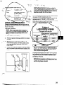
i.0
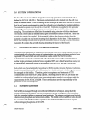
SYSTEM OPERATIONS
The Biocell located at Lot 203 is designed to treat only petroleum contaminated soil ;as
defined in N.C.G.S. 143-215.1. Petroleum contaminated soil is loaded into the cell vii a
dozer or tracked loader, Prior to loading the soil a sample is taken from the soil to confirm
that the soil meets requirements to enter the cell and to get a baseline for nutrient addition.
The material is spread over the cell in a l-foot lift. Nutrients are applied in dry granular
form using a conventional spread caster at a rate based upon initial baseline nutrient
sampling. The nutrients are tilled into the material using a tractor with disc attachment.
The Biocell is then tilled as needed based upon the moisture content of the soil. After one
month, the material is sampled. %fthe material is below the cleanup criteria, then the
material is loaded out and stored awaiting final disposition by the base. If the material is
above the cleanup criteria, then the process continues until the cleanup criteria is attained.
Appendix B contains the as-built drawing depicting the layout of the biocell.
1.1
INCOMING
MATERIAL
ACCEPTANCE
TESTING
Petroleum soils identified for treatment at this facility from MCB Camp Lejeune include: (1)
contaminated soils where the source of contamination was virgin petroleum products from
regulated USTs and which are not hazardous wastes under the North Carolina
Administrative
Code; (2) contaminated soils where the source of the contamination is
neither virgin petroleum products from a regulated UST, nor a listed hazardous waste, nor
a characteristic hazardous waste in accordance with the TCLP test (40 CFR 261.24)
Soils which are characteristically
hazardous for RCRA metals (Arsenic, Barium, Cadmium,
Lead, Mercury, Selenium, Silver, or Chromium) or volatile and semi-volatile organics cannot
be managed at this facility.
Therefore, prior to acceptance and treatment of TPH
contaminated soils from MCB Camp Lejeune, incoming loads to the Lot 203 facility are
certified as nonhazardous based upon appropriate testing results in accordance with the
requirements of 15A NCAC 2H.0200. These certifications are the responsibility of the
generator of each incoming load.
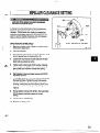
1.2
NUTKIENT
ADDITION
Soil fertility is managed through conventional fertilization techniques, using rela%ively
soluble commercial fertilizers. The soil biotreatment facility is designed to accommodate
both dry granular fertilizer or aqueous based nutrients. The primary nutrients used include
diammonium phosphate and ammonium sulfate. The initial nutrient addition ratios should
be consistent with North Carolina regulations for dedicated facili%ies based on organic
carbon:ni%rogen:phosphorus
of 60:1:.075.
O&M
Manual
l-1
Om/16032
The application rate is determined from baseline carbon:nitrogen:phosphorus
present in the
untreated soil. Total organic carbon concentration in the untreated soil is used to establish
the baseline nutrient addition rates.
Nutrient are applied in dry granular form using a conventional spread caster. The relatively
small size of the treatment area favors the use of dry reagents which are manually applied
by operation personnel.
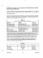
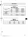
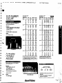
Nutrient levels will be measured in the biocell prior to each separate l,OOO-cubic yard batch
treatment and monthly during operation and maintenance. Composite soil samples will be
analyzed for the following parameters and frequency:
Nutrient
IParameter
Table 1.1
Monitoring
Sampling
I Method
SW-846 Method
Total Organic Carbon
1Ammonium-Nitrogen
and Analysis
Method
33-3, 33-4
Phosphate-Phosphorous
ASA/SSSA
Method
24-5.1, 24-5.3
PH
Moisture Content
ASA/SSSA
Method
12-2.6
ASA/SSSA
Method
21-22
Density
I
( Initial, Monthly
1
9060
1ASA/SSSA
Bacterial Population
1Frequency
Initial, Monthly
I
SM BWW 9215B
The Biocell is divided into six equal quadrants for nutrient monitoring purposes. Grab
samples should be collected by personnel approximately 6 inches from the surface from the
middle of each of the six quadrant locations and composited into three samples. The
samples should be numbered sequentiahy and sent with a chain-of-custody
for off-site
analysis. The results are compared with the target nutrient ratios and adjusted as
necessary to maintain biological treatment efficiency and modify the operating plan as
needed. Nutrient monitoring will continue monthly until the batch reaches the soil
treatment standards listed below in Table 1.2.
Table 1.2
Method Number
Cleanup Ctitti
TPH/GRQ
5030/8015
<lOmg/kg
TPH/DRO
3550/8015
~40 mg/kg
Oil and Grease
O&M Manual
9071
l-2
1
~250 mg/kg
OHM/lfSO32
O&M
Manual
1-3
0HM/16032
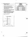
WATER MANAGEMENT
1.3
Because soil microorganisms inhabit and are only active within thin films of water, the soil
water content is maintained at an optimal condition for their growth. Soil water moisture
content is monitored on-site using an oven as needed. Initial and monthly moisture
measurements will be performed in accordance with Table 1.1. The target soil moisture
content is approximately
60 to 80 percent of the field holding capacity corresponding to
between 10 and 15 percent moisture on a weight basis. The percent moisture can vary
depending on the material being treated. Table 1.3 shows the data sheet used to calculate
the percent moisture. Because the driest soil conditions will occur at or near the surface,
soil samples should be obtained from 0 to 4 inches. Soil at this depth is subject to the
greatest drying. Six sample locations are selected, one from each quadrant, and composited
into three samples prior to analysis.
Stormwater and leachate which is collected in the biocell sump is pumped into the 20,000gallon holding tank adjacent to the facility. Water is applied to the biocell for moisture
control as necessary from this tank using a centrifugal pump and a sprinkler system.
Moisture monitoring results from the biocell quadrants are used to determine recycle .rates.
In case of excess stormwater and leachate, the water is transferred to the water treatment
plant located adjacent to the facility.
1.4
SOIL MIXING
AND AERATION
Following the initial application of fertilizer, soil will be thoroughly mixed to distribute hot
spots of contamination and reduce soil particle size. Once the soil fertility and moisture
regimes are optimized, the factor limiting growth of soil microorganisms is usually oxygen
Oxygen is supplied by conventional tilling methods, which thoroughly mixes and loosens
the soil. A conventional farm tractor with tiller attachment is used for this purpose.
Several overlapping passes of the equipment will be performed longitudinally
in rows in the
north-south direction.
The entire biocell will be tilled to the full depth of the
contaminated soil immediately following initial moisture and nutrient additions and
turned twice per month during the operation and maintenance period or as needed.
1.5
SAMPLING
AND ANALYSIS
Collection and analysis of soil samples will be performed at three different
batch of petroleum contaminated soil. They are as follows:
*
0
l
O&M
times for each
Initial characterization of incoming soils
During the O&M period for performance monitoring
At the completion of treatment for confirmation sampling
Manual
1-4
OHM/%6032
Table 1.3 - Percent Moisture
Lot 203 Biocell
O&M
Manual
l-5
Data
OHM/16032
Initial Characterization
Baseline soil samples will be collected from the placed lift prior to initiating treatment for
each batch, and periodically thereafter. The treatment cell (1000 cubic yards) will be
divided into 6 equal quadrants for baseline sampling and analysis. Representative
samples will be taken with a soil hand auger or other sampling device from each of the six
quadrants and composited into three samples for off-site analysis. The samples will be
analyzed for the following:
l
l
Average total petroleum
Method 5030/8015;
hydrocarbon
concentration
(mg/kg
TPFH) using EP,A
Average total petroleum
Method 3550/8015;
hydrocarbon
concentration
(mg/kg
TPFH) using EP,A
l
Concentration
of Oil and Grease (mg/kg)
l
Section 1.2, Table 1.1 parameters.
using EPA Method 9071; and
Baseline soil contaminant concentrations for both light and heavy fraction hydrocarbons
will be identified.
This information will be used to determine nutrient loadings and predict
treatment time needed to achieve the specified standards. Following each sampling event,
the equipment will be decontaminated by OHM personnel using a three-step process in
accordance with standard operating procedures.
Performance Monitoring
Monitoring during the O&M period consists of measuring total organic carbon, available
nutrients, moisture, microbial population and pH which are key for optimizing biological
degradation. These parameters, methods, and frequencies were previously provided in
Section 1.2, Table 1.1.
Confirmation Sampling
At the end of each month, confirmation soil samples are collected by personnel. The same
six quadrants used for initial characterization and performance monitoring are used for
confirmation sampling. One composite sample per two quadrants are obtained and
analyzed by an off-site laboratory using the same methods as performed in the initial
characterization as described above. The laboratory results are evahrated to compare the
effectiveness of treatment in removing hydrocarbons to below the treatment criteria. An
evaluation is made whether the cleanup objectives have been attained or to continue
treatment.
O&M
Manual
l-6
OHM/16032
If the soil analyses indicate continued presence of elevated petroleum hydrocarbons,
additional nutrients are applied to the soils and the biodegradation process will contmue.
Treatment time will vary depending on the contaminant type, initial concentrations, and
time of year the treatment is employed. Treatment times will be shorter in the summer due
to the higher degree of biological activity during the warmer summer months.
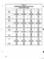
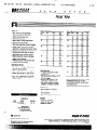
Sampling Summa y and QAIQC
Table 3 provides a summary of the sampling to be performed at the site for initial
characterization, ongoing operation and maintenance, and final confirmation.
The table
includes sample type, frequency, methods, turnaround times, sample quality control levels,
preservation and sampling techniques. Off-site analyses wiIl be performed by an NFESC
and North Carolina approved laboratory.
1.6
TREATED
SOIL REMOVAL
AND BIOCELL
RECONDITIONING
Following confirmation testing, and completion of treatment to the specified standards, the
soil is pushed with a light bulldozer into stockpiles within the contained biocell for
placement outside the biocell at the designated location. The soil is directly loaded onto
transport vehicles parked on the ramp using a front-end loader or excavator. Although the
material is nonhazardous, each truck should be inspected by operations personnel to ensure
that vehicles are properly loaded, tarped if required.
The sand drainage layer is inspected following removal of the treated soil and prior t:o
arrival of the next batch. Replacement sand is provided and spread proportionally
if
necessary following a visual survey of the biocell.
1.7
RESIDUALS
MANAGEMENT
During the course of installation and operations, small amounts of contaminated debris
including personnel protective equipment and nonhazardous rinse water is generated. The
nonhazardous debris is containerized and stored on-site until transportation
and disposal
can be arranged. Nonhazardous liquids are processed through the nearby groundwater
treatment facility.
O&M
Manual
1-7
Ol!-IW16032
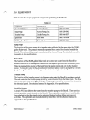
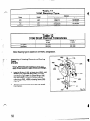
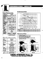
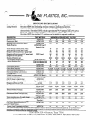
Table 2.1 lists %hemajor equipment
components
Table
pertaining
to the Biocell.
2.1
Component
Manufacturer
Phone
20-mil HDPE liner
In-Line
(800) 364-7688
SUP-P
Aurora Pumps, Inc.
(419) 289-3042
Transfer Pump
Goulds Pumps, Inc.
(800) 446-8537
Sprinklers
Rain Bircl
(602) 741-6100
Baker Tanks
(800) 946-4646
20,000-gallon
Tank
Plastics
4
Sump Pump
The function of the sump pump is to transfer water collected in the sump into the 20,000gallon Baker tank The pump is manually operated by a control box located outside the
Biocell. The submersible pump is manufactured by Aurora Pump. See attached manual in
Appendix A for specifications.
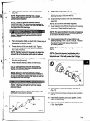
Baker Tank
The function of the 20,OOOgallon Baker tank is to store rain water from the Biocell for
moisture control or for subsequent treatment at the adjacent groundwater treahnent plant.
Water is pumped into me top of the tank from the sump pump and out via the transfer
pump. To transfer water to the groundwater treatment plant, water is pumped by a 2-inch
pump through flexible hose into the groundwater treatment plant wet well.
Transfer Pump
The function of the transfer pump is to disperse water onto the Biocell for moisture control.
The seal water for the Goulds pump is fed by water diverted from the Baker tank The flow
rate for the seal water is 0.5 gpm at 20 psi. The pump is started by a control box located at
the electrical panel. See attached manual in Appendix A for specifications.
Sprinkler
System
A 2-inch PVC line delivers the water from the transfer pump to the Biocell. There are four
mobile sprinkler stands located on the Biocell. These sprinkler stands have l-inch flexible
hose attached so that the stands can be relocated during loading, tilling and removal
activities. The sprinklers are manufac%ured by Ram Bird. See the attached manual in
Appendix A for specifications.
O&M Manual
2-l
QHlU/16032
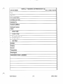
Table 2.2 shows the Operation and Maintenance Log completed daily. Technical data
sheets or manuals for the items listed above are located in Appendix A. Only one of the
items requires regular routine maintenance. That is the Goulds Pump. Refer to Section 5.0
of its manual in Appendix A for routine maintenance items.
O&M Manual
2-2
OHM/16032
Table 2.2 - Operation
and Maintenance
Log
MCB Camp Lejeune
Lot 203 Biocell
Date
Operator
Soil Loaded (YD)
Soil Removed (YD)
Manifest No.
Nutrient
Addition
---I
Moisture Content
Check
I
S-P
I
Goulds P-p
-p
Storage Tank Level
I
Samples Taken
Soil Tilled
--i
NOTES:
Weather
Rainfall
Temperature
Wind Speed
Maintenance
Q&M Manual
Issues/Comments
2-3
QHM/16032
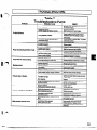
Appendix A
Technical
Data Sheets
installation, Operation and Maintenance Instructions,
A.
*.
.-
_:
...:Y. .
Model 3196 XL T-X
Model 3196
@ 1993 Goulds Pumps, Inc.
. .-.
. .
‘.,
::
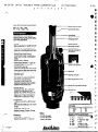
This manual provides instructions for the Installation,
Operation, and Maintenance
of the
Goulds Model 3196 ANSI Standard Dimension Process Pump. This manual covers the
standard product plus common options that are available.
Fqr special options, supplemental
instructions are supplied.
This manual must be read and understood
before installation
and start-up.
4
The design, materials, and workmanship
incorporated
in the construction
of Goulds pumps
makes them capable of giving, trouble-free
service. The life and satisfactory
service of any
mechanical unit, however, is enhanced and extended by correct application, proper
installation,
periodic inspection, condition monitoring and careful maintenance.
This instruction
manual was prepared to assist operators in understanding
the construction
and the correct
methods of installing, ‘operating, and maintaining these pumps.
Goulds shall not be liable for physical
observe the instructions
for Installation,
manual.
Warranty
is valid only
when
genuine
injury, dainage or delays caused by a failure to
Operation,
and Maintenance
contained
iin this
Goulds
parts
5.
... ..,‘.,G$
:
:I...’
are used.
Use of the equipment on a service other than stated in the order will nullify the wairanty,
unless written approval is obtained in advance from Goulds Pumps, Inc.
Supervision
installation.
by an authorized
Additional manuals
calling l-800-446-8537.
Goulds
can be obtained
representative
by contacting
THIS MANUAL
n
n
n
n
n
n
n
is recommended
your local Goulds
EXPLAINS
Proper Installation
Start-up Procedures
Operation Procedures
Routine Maintenance
Pump Overhaul
Trouble Shooting
Ordering Spare or Repair
Parts
to assure proper
representative
or by
SECTION
Page
.
.
.--
,.
._.*
.
-__c^J_-
__-_-
--..
-----.
.^
..
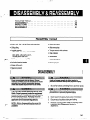
DEFINITIONS
. . . . . . . . . . . . . . . . . . . . . . . . . . . . . . . . . 7
GENERAL PRECAUTIONS
. . . . . . . . . . . . . . . . . . . . . . . . . . 7
l
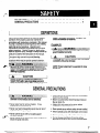
DEFINITIONS
NOTE: Operating
which is essential
This pump has been designed for safe and reliable
operation when properly used and maintained in
accordance
with instructions contained in this manual.
A pump is a pressure containing device with rotating
parts that can be hazardous.
Operators and
maintenance
personnel must realize this and follow
Goulds Pumps Inc. shall not be
safety measures.
liable for physical injury, damage or delays caused by
a failure to observe the instructions in this manual.
Throughout
this manual the words Warning,
Caution, and Note are used to indicate procedures
situations which require special operator attention:
or
procedure,
to observe.
condition,
etc.
without
coupling
EXAMPLES
Pump shall never be operated
guard installed
correctly.
1A
CAUTION
Throttling
cavitation
flow from the suction
and pump damage.
NOTE: Proper
pump life.
Warning is used to indicate the presence
of a
hazard which m cause severe personal
injury,
death, or substantial
property
damage if the
warning
is ignored.
I A
I
aiignmen
side may cause
t is essen tiai for long
CAUTION
caution is used to indkate the pmsemx
h~which~orEiZLIwuseminorpersonal
injury or property &mqe
if the warning
of a
is ignonzd.
GENERAL PRECAUTIONS
Personal
outlined
Never start pump without
liquid in pump casing).
injuries will result if procedures
in this manual are not followed.
Never apply heat to remove impeller.
explode due to trapped liquid.
Never use heat to diassemble
explosion from trapped liquid.
It may
pump due to risk of
Never operate pump without
correctly installed.
coupling
guard
Never operate pump beyond
which the pump was sold.
the rated conditions
to
proper
prime (sufficient
l
Never run pump below recommended
flow or when dry.
l
Always lock out power to the driver before
performing pump maintenance.
l
Never operate pump without safety devices installed.
l
Never operate
pump with discharge
l
Never
pump with suction valve closed.
l
Do not change conditions
approval of an authorized
operate
minimum
valve closed.
of service without
Goulds representative.
7
PUMP DESCRIPTION
.............................
.........................
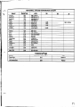
NAMEPLATE
INFORMATlON
RECEIVING THE PUMP ...........................
Storage Requirements.
...........................
Handling
..................................
9
10
-11
11
.I1
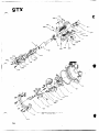
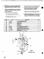
PUMP DESCRIPTION
The Model 3196 is a horizontal overhung, open
impeller centrifugal pump that meets requirements of
ANSI 873.1.
Adapter - The ductile iron frame adapter has
machined rabbet fit to the seal chamber/stuffing box
cover and precision dowel pin f’it to the bearing frame.
Frame
5 pump sizes
End - Oil level is viewed through a sight glass.
Optional oil cooling is provided by a finnedl tube.
Flood oil lube is standard. The power end is sealed
with Goulds designed labyrinth seals. No machining
is required to convert from oil to grease or oil mist.
Regreaseable bearings, greased for life bearings and
oil mist lubrication are optional.
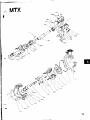
MTX
15 pump sizes
Shaft
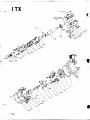
LTX
11 pump sizes
XLT-X
5 pump sizes
x17
3 pump sizes
- The inboard bearing carries only radial
load, it is free to float axially in the frame. The
outboard bearing is shouldered and locked to the
shaft and housing to enable it to carry radial and
thrust loads. All fits are precision machined to industry
standards. The inboard bearing is a single row deep
groove ball bearing. The outboard bearing is a double
row angular contact bearing, except for the LTX which
uses a pair of single row angular contact ball bearings
.
mounted back to back.
Power
The model is based on 5 power ends and 28
hydraulic pump sizes. Groupings are as follows:
~ STX
- The casing is top centerline discharge and
self-venting. The gasket is fully confined. An integral
foot support is used for maximum resistance to
misalignment and distortion from piping loads. ANSI
flat face serrated flanges are standard. ANSI Class
’ 150 raised face serrated, ANSI Class 300 flat face
serrated and ANSI Class 300 raised face serrated are
available.
Casing
- The impeller is fully open and threaded to
the shaft. The threads are sealed from the pumpage
by a Teflon O-ring.
Impeller
- The shaft is available with or witholut sleeve.
Bearings
Seal - A dynamic seal is available which
uses a repeller to pump liquid out of the stuffing box
while the pump operates, a static seal prevents
leakage when the pump is shut down.
Dynamic
Direction
of Rotation
- Clockwise (right hand) as
viewed from the driver, looking at the pump shaft.
Cover - The 3196 is
available with a stuffing box cover designed for
packing and BigBoreTM seal chamber or TaperBoreTM
seal chamber for improved performance of
mechanical seals.
Seal Chamber/Stuffing-Box
9
I
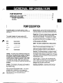
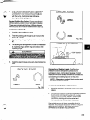
NAMEPLATE INFORMATION
E!!**I
k
!%TA%1-1
CAUTION:
AFTER
STARTING
w t4o~OPERATE
AGAINST
aosm VALVE
5
Fig. 1
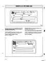
Every pump has two Goulds nameplates that provide
information about the pump. The tags are located on
the casing and bearing frame.
Pump
Casing
Frame Tag - provides information on the
lubrication system used (Fig. 2).
Bearing
When ordering spare parts you will need to identify
pump model, size, serial number, and the item
number of required parts. Information can be taken
from the pump casing tag. Item numbers can be
found in this manual.
.
Tag - provides information about the
pump’s hydraulic characteristics. Note the format of
the pump size: Discharge x Suction - Nominal
maximum Impeller Diameter in inches.
(Example: 2x3-6)(Fig. 1).
Fig. 2
_
10
.,_^
.._
.-..
.-_-.
.‘----.--.-~
,*
‘.
RECEIVINGTHE PUMP
(i
I
Inspect the pump as soon as it is received. Carefully
check that everything is in good order. Make notes of
damaged or missing items on the receipt and freight
bill. File any claims with the transportation company
as soon as possible.
STORAGE REQUIREMENTS
Short Term: (Less than 6 months) Goulds normal
packaging procedure is designed to protect pump
during shipping. Upon receipt store in a covered and
dry location.
Long Term: (More than 6 months) Preservative
treatment of bearings and machined surfaces will be
required. Rotate shaft several times every 3 months.
Refer to driver and coupling manufacturers for their
long term storage procedures. Store in a covered dry
location.
NOTE:’ Long term storage treatment can be
purchased with initial pump order.
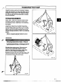
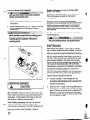
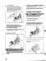
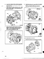
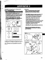
HANDLING
.
Pump and components are heavy. Failure to
proper/y Itft and support equipment could resutt
in serious physical injury, or damage to pumps.
Steel toed shoes must be worn at all times.
Use care when moving pumps. Liiing equipment
must be able to adequately support the entire
assembly. Hoist bare pump using a suitable sling,
under the suction flange and bearing frame.
Baseplate mounted units are moved with slings under
the pump casing and driver. Refer to figures 3A,B,C
for examoles of orooer liftina techniaues.
Fig. 3C
I-
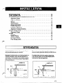
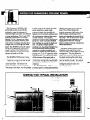
SITE/FOUNDATION
.............................
LEVEL BASEPLATE
.............................
ALIGNMENT
AND ALIGNMENT
PROCEDURE
Alignment Check
.............................
Alignment Criteria .............................
Setup..
................................
Measurement
...............................
Angular Alignment
.............................
Parallel Alignment
.............................
Complete Alignment
............................
Alignment Trouble Shooting .........................
GROUTBASEPLATE
............................
Alignment Check
.............................
PIPING
....................................
General
..................................
Suction Piping ...............................
Discharge Piping
..............................
Final Piping Check .............................
.I3
.I4
.14
.14
.15
..I 5
.15
.I6
.16
.1’7
1’7
.18
.I8
.18
.I8
-19
19
.19
...............
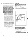
SITE/FOUNDATION
..
A pump should be located near the supply of liquid
and have adequate space for operation,
maintenance, and inspection.
The location and size of the foundation bolts are
shown on outline assembly drawing, provided with the
pump data package.
Baseplate mounted pumps are normally grouted on a
concrete foundation, which has been poured on a
solid footing. The foundation must be able to absorb
any vibration and to form a permanent, rigid support
for the pumping unit.
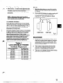
Foundation bolts commonly used are sleeve type
(Fig. 4A) and J type (Fig. 48). Both designs permit
movement for final bolt adjustment.
/ BASEPLATE
‘I
Y
LIJ
A
h
Fig. 4A
4
4
l
*
Fig. 48
I
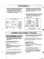
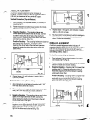
LEVEL’BASEPLATE
Place 2 sets of wedges or shims on the foundation,
one set on each side of every foundation bolt.
The wedges should extend .75 in. (20mm) to
1.5 in. (40mm) above foundation, to allow for
adequate grouting. This will provide even support
for the baseplate once it is grouted.
1.
I
I_
Remove water and/or debris from anchor bolt
holes/sleeves prior to grouting. If the sleeve type
bolts are being used, fill the sleeves with rags to
prevent grout from entering.
3.
Carefully lower baseplate onto foundation bolts.
4.
Level baseplate to within W (3.2mm) over length of
the baseplate and to within -088 in. (1.5mm) over
the width of the base by adjusting wedges.
5.
Hand tighten bolts.
NOTE: Proper alignment
is the responsibility
the installer
and user of the unit.
any alignment
procedure
power is locked out. Failure
power will result in serious
To remove guard refer to coupling guard
assembly/disassembly instructions.
The points at which alignment is checked and
adjusted are:
l
l
1
ALIGNMENT AND ALIGNMENT PROCEDURE
Before beginn&g
make sure driver
to lock out driver
physical injury.
is done prior to operation when
the pump and the driver are at ambient
temperature.
ALIGNMENT CHECKS
Initial
l
l
Final Alignment
Alignment is achieved by adding or removing shims
from under the feet of the driver and shifting
equipment horizontally as needed.
14
of
Accurate alignment of the equipment must be
attained. Trouble free operation can be accomplished
by following these procedures.
Initial Alignment
is done after operation when the
pump and driver are at operating temperature.
\
2.
l
Alignment
(Cold
Alignment)
Before Grouting Baseplate - To ensure alignment
can be obtained.
After Grouting Baseplate - To ensure no changes
have occurred during grouting process.
After Connecting Piping - To ensure pipe strains
haven’t altered alignment. If changes have
occurred, alter piping to remove pipe strains on
pump flanges.
,
Final Alignment
:f@-
l
(Hot Alignment)
Id
li..
SET UP
After First Run - To obtain correct alignment when
both pump and driver are at operating temperature.
Thereafter, alignment should be checked
periodically in accordance with plant operating
procedures.
1.
Mount two dial indicators on one of the coupling
halves (X) so they contact the other coupling half
(Y) (Fig. 6).
2.
Check setting of indicators bv rotatina couoling half
X to ensure indicators stay in contaci;hcith ’
coupling half Y but do not bottom out.. Adjust
indicators accordingly.
NOTE: Alignment check must be made if
process temperature changes, piping changes
and or pump service is performed.
P
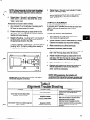
ALIGNMENT CRITERIA
Good alignment is achieved when the dial indicator
readings as specified in the alignment procedure are
.002 in. (.05 mm) Total Indicated Reading (T.I.R.) or
less when the pump and driver are at operating
temperature (Final Alignment).
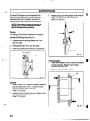
During the installation phase, however, it is necessary
to set the parallel alignment in the vertical direction to
a different criteria due to differences in expansion
rates of the pump and driver. Table 1 shows
recommended preliminary (cold) settings for electric
motor driven pumps based on different pumpage
temperatures. Driver manufacturers should be
consulted for recommended cold settings for other
types of drivers (steam turbines, engines, etc.)
Table 1
Cold Setting of Parallel
Vertical Alignment
PUMPAGETEMPERATURE
SI’F (1O’C)
1SF (WC)
25o.F (12O’C)
35o.F (175’C)
45O.F (218.C)
SET DRIVER SHAFT
.C02in. (.05mm) LOW
.OOlin. (.03mm) HIGH
.OO5in. (.12mm) HIGH
.009in. (.23mm) HIGH
.013in. (.33mm) HIGH
5WF (228%)
.017in. (&mm)
HIGH
Fig. 6
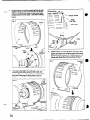
MEASUREMENT
1. To ensure accuracy
of indicator readings, always
rotate both coupling halves together so indicators
contact the same point on coupling half Y. This
will eliminate any measurement problems due to
runout on coupling half Y.
2.
Take indicator measurements with driver feet
hold-down bolts tightened. Loosen holld down
bolts prior to making alignment corrections.
3.
Take care not to damage indicators when moving
driver during alignment corrections.
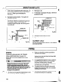
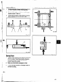
ANGULAR ALIGNMENT
A unit is in angular alignment when indicator A
(Angular indicator) does not vary by more that ,002 in.
(.05 mm) as measured at four points 90” apart.
Vertical
Correction
(Top-to-Bottom)
1.
Zero indicator A at top dead center (12 o’clock) of
coupling half Y.
2.
Rotate indicators to bottom dead center (6 o’clock).
Observe needle and record reading.
3.
Negative
Reading
- The coupling halves are
further apart at the bottom than at the top. Correct
by either raising the driver feet at the shaft end
(add shims) or lowering the driver feet at the other
end (remove shims), (Fig. 7A).
Fig. 78
4.
Repeat steps 1 through 3 until indicator A reads
in. (.05 mm) or less.
.002
5
Recheck both horizontal and vertical readings to
ensure adjustment of one did not disturb the
other. Correct as necessary.
Positive Reading - The coupling halves are closer at
PARALLELAUGNMENT
the bottom than at the top. Correct by either
lowering the driver feet at the shaft end (remove
A unit is in parallel alignment when indicator P
shims) or raising the driver feet at the other end
(parallel indicator) does not vary by more than .002 in.
(add shims).
(.05 mm) as measured at four points 90’ apart at
operating temperature. Note the preliminary vertical
cold setting criteria, Table 1.
Vertical
SHIMS
4.
Fig. 7A
nepeat . steps l-3 - untrl.. indicator A reads .002 in
(.05 mm) or less.
Horizontal
Correction
(Side-to-Side)
1.
Zero indicator A on left side of coupling half Y, 90”
from top dead center (9 o’clock).
2.
Rotate indicators through top dead enter to the right
side, 180” from the start (3 o’clock). Observe
needle and record reading.
3.
Negative
Reading - The coupling halves are further
apart on the right side than the left. Correct by
either sliding the shaft end of the driver to the left
or the other end to the right.
Positive Reading - The coupling halves are closer
together on the right side than the left. Correct by
either sliding the shaft end of the driver to the
right or the other end to the left (Fig. 78).
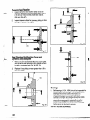
Correction
(Top-to-Bottom)
1.
Zero indicator P at top dead center of coupling
(12 o’clock) half Y (Fig. 6).
2.
Rotate indicator to bottom dead center (6 o’clock).
Observe needle and record reading..
3.
Negative Reading
- Coupling half X is lower than
coupling half Y. Correct by removing shims of
thickness equal to half of the indicator reading
under each driver foot.
Reading
- Coupling half X is higher than
coupling half Y. Correct by adding shims of
thickness equal to half of the indicator reading
from each driver foot (Fig. 8A).
Positive
kl#
#El
SHIMS
16
__
.-. _.._,.______.__
ud
Fig. 8A
NOTE: Equa/ amounts of shims must be added
to or removed
from each driver foot. Otherwise
the vertic?l angular alignment
will be affected.
.F--4.
Repeat steps 1 through 3 until indicator P reads
.002 in. (.05 mm) or less.
5.
Re-check both horizontal and vertical readings to
ensure adjustment of one did not disturb the
other. Correct as necessary.
Repeat steps 1 through 3 until indicator P reads
within .002 in. (.05 mm) or less when hot, or per
Table 1 when cold.
Horizontal
Correction
COMPLETEALIGNMENT
(Side-to-Side)
1.
Zero indicator P on the left side of coupling half Y,
90” from top dead center (9 o’clock).
2.
Rotate indicators through top dead center to the
right side, 180” from the start (3 o’clock). Observe
needle and record reading.
3.
4.
- Coupling half Y is to the left of
coupling half X. Correct by sliding driver evenly in
the appropriate,direction (Fig. 88).
Negative
A unit is in complete alignment when both indicators
A (angular) and P (parallel) do not vary by more than
.002 in. (.05 mm) as measured at four points
90’ apart.
Vertical
(Top-to-Bottom)
.l.
Zero indicators A and P at top dead center
(12 o’clock) of coupling half Y.
2.
Rotate indicator to bottom dead center (6 o’clock).
Observe the needles and record the readings.
3.
Make corrections as outlined previously,
Reading
Positive Reading - Coupling half Y is to the right of
coupling half X. Correct by sliding driver evenly in
the appropriate direction.
Correction
Horizontal
Correction
(Side-to-Side)
1.
Z&o indicators A and P on the left side of coupling
half Y, 90’ from top dead center (9 o’clock).
2.
Rotate indicators through, top dead center to the
right side, 180” from the start (3 o’clock). Observe
the needle, measure and record the reading.
3.
Make corrections as outlined previously.
4.
Recheck both vertical and horizontal readings to
ensure adjustment of one did not disturb the
other. Correct as necessary.
Fia. 88
NOTE: Failure to slide motor
horizontal
angular correction.
evenly
will affect
Alignment
PROBLEM
NOTE: With experience,
fhe installer will
understand
the interaction
between angular and
parallel and will make corrections
appropriately.
Table 2
Trouble Shooting
PROBABLE CAUSE
REMEDY
hold down bolts and slide pump
and driver until horizontal alignment is
acheived.
Determine which comer(s) of the baseplate are
high or low and remove or add shims at the
appropriate comer(s) and realign.
Determine if center of baseplate should be
raised or lowered and correct by evenly adding
or removing shims at the center of the
Loosenpump
Driver feet bolt bound.
Cannot obtain horizontal (Side-to-Side)
alignment, angular of parallel
Cannot obtain vertical (Top-to-Bottom) alignment,
angular or parallel
Baseplate not leveled
properly, probably twisted.
Baseplate not leveled
properly, probably bowed.
17
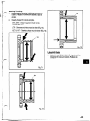
GROUT BASEPLATE
1.
Clean areas of baseplate that will contact grout. Do
not use oil-based cleaners because grout will not
bond to it. Refer to grout manufacturer’s
instructions.
2.
Build dam around foundation.
foundation (Fig. 9A).
3.
Pour grout through grout hole in baseplate, up to
level of dam. Remove air bubbles from grout as it
is poured by puddling, using a vibrator, or
pumping the grout into place. Non-shrink grout is
recommended.
/.
4.
Allow grout to set.
5.
Fill remainder of baseplate with grout. Remove air
as before (Fig. 9B).
6.
Allow grout to set at least ,48 hours.
Tighten foundation bolts.
Thoroughly wet
BASEPLATE
7.
.
4
ALIGNMENT CHECK
Fig. 9A
Recheck alignment before continuing, using methods
previously described.
PIPCNG
GENERAL
Guidelines for piping are given in the “Hydraulic
Institute Standards” available from: Hydraulic
Institute, 30200 Detroit Road, Cleveland, OH
44145-l 967 and must be reviewed prior to pump
installation.
Never draw piping into place by forcing at the
flanged
connections
of the pump. This may
impose dangerous
strains on the unit and
cause misalignment
between pump and drivereipe strain will adversely
effect the operation
of
the pump resulting in physical
injury and
damage to the equipment.
n
1.
18
All piping must be supported independently
line up naturally with, the pump flanges.
of, and
2.
Piping runs should be as short as possible to
minimize friction losses.
3.
DO NOT connect piping to pump until grout has
hardened and pump and driver hold-down bolts
have been tightened.
4.
It is suggested that expansion loops or joints be
properly installed in suction and/or discharge
lines when handling liquids at elevated
temperatures, so linear expansion of piping will
not draw pump out of alignment.
5.
The piping should be arranged to allow pump
flushing prior to removal of the unit on services
handling corrosive liquids.
6.
Carefully clean all pipe parts, valves and fittings.
and pump branches prior to assembly.
SUCTION PIPING
NPSHA must always exceed NPSUR as shown
on Goulds performance cunres received with
order. (Reference
Hydraulic Institute for NPSH
and pipe friction values needed to evaluate
suction piping.
L
Properly installed suction piping is a necessity for
trouble-free pump operation. Suction piping should be
flushed BEFORE connection to the pump.
1.
2.
5.
ihe size of entrance from supply should be one or
two sizes larger than the suction pipe.
6.
The suction pipe must be adequately submerged
below the liquid surface to prevent votices and air
entrainment at the supply.
DISCHARGE PIPING
1.
Isolation and check valves should be installed in
discharge line. Locate the check valve between
isolation valve and pump, this will pennit
inspection of the check valve. The isolation valve
is required for priming, regulation of flow, and for
inspection and maintenance of pump. ‘The check
valve prevents pump or seal damage due to
reverse flow through the pump when the driver is
turned off.
2.
Increasers, if used, should be placed between pump
and check valves.
3.
Cushioning devices should be used to protect the
pump from surges and water hammer if
quick-closing valves are installed in system.
Use of elbows close to the pump suction flange
should be avoided. There should be a minimum
of 2 pipe diameters of straight pipe between the
elbow and suction inlet. Where used, elbows
should be long radius.
Use suction pipe one or two sizes larger than the
pump suction, with a reducer at the suction
flange. Suction piping should never be of smaller
diameter than the pump suction.
3.
Reducers, if used, should be eccentric, at the pump
suction flange, with sloping side down.
4.
Pump must never be throttled on suction side.
5.
Suction strainers, when used, must have a net “free
area” of at least three times the suction pipe area.
6.
Separate suction lines are recommended when
more than one pump is operating from the same
source of supply.
#PC”;
Suction
lift conditions
1.
Suction pipe must be free from air pockets.
2.
Suction piping must slope upwards to pump.
3.
All joints must be air tight.
4.
A means of priming the pump must be provided,
such as a foot valve.
Suction
head/Flooded
suction
conditions
1.
An isolation valve should be installed in the suction
line at least two pipe diameters from the suction
to permit closing of the line for pump inspection
and maintenance.
2.
Keep suction pipe free from air pockets.
3.
Piping should be level or slope gradually downward
from the source of supply.
4.
No portion of the piping should extend below pump
suction flange.
FINAL PIPING CHECK
After connecting
the piping
to pump:
1.
Rotate shaft several times by hand to lbe sure that
there is no binding and all parts are free.
2.
Check alignment, per the alignment procedure
outlined previously to determine absence of pipe
strain. If pipe strain exists, correct piping.
-
PREPARATION
FOR START-UP
......................
Checking Rotation .............................
Check Impeller Clearance
.........................
Couple Pump and Driver
.........................
Lubricating Bearings ............................
Shaft Sealing
...............................
Priming Pump ...............................
STARTING
PUMP
..............................
OPERATION
.................................
General Considerations
...........................
Operating at Reduced Capacity ......................
....................
Operating under Freezing Conditions
SHUTDOWN
.................................
FINAL ALIGNMENT
.............................
.21
.21
.21
-22
.22
.22
.24
.25
.26
.26
.26
.26
.26
.26
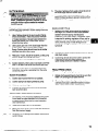
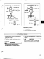
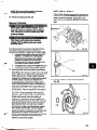
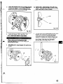
PREPARATION FOR START-UP
,.e-.. CHECKING ROTATING
\*, 1 A
CAUTION
:f
.
Serious damage may result if pump is run in the
vong robtion.
1.
Lo&
I
Make sure coupling hubs are securely fastened to shafts.
NOTE= Pump is shipped
removed.
3.
4.
5.
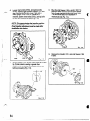
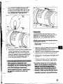
lmpler Front ClearanceInch (mm)
,005 (.13)
.cQ8(20)
.015 (36)
The maximum impeller setting should not be set more
than .005 inch (0.13mm) above values in table or
significant performance
degradation
will result.
out power to driver.
Lock out driver power to prevent accidental
start-up and physical injury.
2.
Frame Designation
STX
Mix, LTX
XLTX, Xl 7
with coupling
spacer
Unlock driver power.
Make sure everyone is clear. Jog driver just long
enough to determine direction of rotation. Rotation
must correspond to arrow on bearing housing.
Lock out power to driver.
Also, for pumpage temperatures
above 200 degrees
F (93 degrees C) the cold (ambient) setting must be
increased per Table 3. This is necessary to prevent
the impeller from contacting the casing due to
differential expansion from the higher operating
temperatures.
See Preventative
Maintenance
section
CHECK IMPELLER CLEARANCE
Prior to starting the pump the impeller clearance must
be checked. The pump efficiency is maintained when
the proper impeller clearance is set. The optimum
hydraulic performance
is attained by setting the
impeller front clearance at the factory to
’ -3redetermined
limits which are consistent with service
sonditions.
a
3” (58mm)
5” (.64mm)
Grease
grease.
COUPLE PUMP AND DRIVER
Lock out driver power to prevent
rotation and physical
injury.
coupling
accidental
Lubrication:
Pumps are shipped
See Table 6.
with
Greased For Life Bearings:
These bearings
filled with grease and sealed by the bearing
are
manufacturer.
1.
Install and lubricate
instructions.
per manufacturer’s
2.
Install coupling guard (Fig. 12). Refer to Coupling
Guard Installation and Disassembly Section
(Appendix II).
Never operate a pump without coupling
guard
properly
installed.
Refer to Appendix
I1 for
coupling
guard installation
instructions.
Personal
injury will occur if pump is run without
coupling
guard.
If pump is put into operation after prolonged
shut-down, flush out bearings and bearing frame with
a light oil to remove contaminants.
During flushing
rotate shaft slowly by hand. Finally, flush bearing
housing with proper lubricating oil to insure oil quality
after cleaning.
See Preventive
Maintenance
recommendations.
Operation
will cause
section for lubrication
of the unit without proper lubrication
bearing failure, and pump seizure.
SHAFT SEALING
Mechanical
Seal Option: Pumps may be shipped
with or without mechanical seals installed. A. common
seal with this model is the cartridge type. Cartridge
seals are preset at the seal manufacturer’s
facility and
require no field settings. Cartridge Seals installed by
the user require removal of the holding clips prior to
operation, allowing the seal to slide into place. If the
seal has been installed in the pump at the Goulds
factory, these clips have already been removed. For
other types of mechanical seals, refer to the seal
manufacturer’s
instructions for installation and setting.
Connection
of Sealing Liquid: For satisfactory
operation, there must be a liquid film between seal
faces to lubricate them. Refer to seal manufacturer’s
drawing for location of taps. Some methods which
may be used to flush/cool the seal are:
Fig. 12
LUBRICATING BEARINGS
CAUTION
I A
Pumps
are shipped
without
oil.
Oil Lubrication:
Fill bearing frame with oil, through
filler connection (located on top of bearing frame refer
to Fig. 188) until oil level reaches the middle of the
sight-glass . A high quality turbine type oil, with rust
and oxidation inhibitors should be used.
r”l
Pure Oil Mist Lubrication:
Oil mist is an optional
feature for the 3196. Follow oil mist generator
manufacturer’s
instructions. The inlet connections
are
located on the top of the bearing frame, connection
points are covered under lubrication.
(Refer to
Apprendix I on converting lubrication).
22
a.
Product Flushing - In this arrangement,
the
pumpage is piped from the casing (and cooled in
an external heat exchanger when required) then
injected into seal gland.
b.
External Flush - A clean, cool compatible liquid is
injected from an outside source directly into seal
gland. Flushing liquid must be at a pressure 5-15
PSI (0.35-l .Ol kg/cm*) greater than the stuffing
box/seal chamber pressure. Injection rate should
be V2-2 GPM (2-8 LPM).
c.
f--
Other methods may be used which make use of
multiple gland connections and/or stuffing box
connections. Refer to documentation supplied
with the pump, mechanical seal reference
drawing, and piping diagrams.
LANTERN
RINGS
Packed Stuffing Box Option: Pumps are shipped
without packing, lantern ring or spilt gland installed.
These are included with the box of fittings shipped
with the pump and must be installed before start-up,
Installation
of packing:
1.
Carefully clean stuffing box bore.
2.
Twist the packing just enough to get it around the
shaft (Fig. 13A,B).
3.
Insert packing, staggering the joints in each ring by
90’.
4.
The stuffing box arrangement in order of installation
is: 2 packing rings, lantern ring (one piece), then
3 packing rings.
Fig. 138
LANTERN
LANTERN
RING
FLUSH
CONNECTION
RING
SPLIT GLANO
(NON-QUENCH
5.
4
Install the gland halves and evenly hand tighten the
nuts.
PACKING
8
CORRECT
1
Fig. 14
of Sealing Liquid: If stuffing box
pressure is above atmospheric pressure and
pumpage is clean, normal gland leakage of 40-60
drops per minute is usually sufficient to lubricate and
cool packing and sealing liquid is not required.
Connection
RINGS
NOTE: Otherwise
if a clean pumpage
0
WRONG
Fia. 131
a product
exists.
flush
can be used
An external sealing liquid is required when:
1.
Abrasive particles in pumpage could score shaft
sleeve.
2.
Stuffing box pressure is below atmospheric pressure
due to pump running with suction lift, ‘or when
suction source is under vacuum. Under these
conditions, packing will not be cooled and
lubricated and air will be drawn into pump.
If an outside source of clean compatible liquid is
required, the pressure should be 15 PSI (1 .O kg/cm2)
above suction pressure. The piping should be
connected to the lantern ring connection.
23
NOTE: Most packing requires lubrication.
Failure to lubricate packing may shorten the life
of the packing and pump.
Dynamic Seal Option: The dynamic seal consists of
two seals: a repeller that prevents leakage during
pump operation and a secondary seal that prevents
leakage when the unit is off. The repeller acts as a
pump to prevent liquid from entering the stuffing box
during pump operation. The repeller does not require
a flush except for services which allow a build-up of
solids on the repeller. A flush hole can be provided
for this purpose. A drain hole can also be supplied to
drain repeller chamber if danger of freezing exists.
PRIMING PUMP
Never start the pump until it has been properly
primed. Several different methods of priming can be
used, depending upon type of installation and service
involved.
Suction Supply Above Pump:
1.
Slowly open the suction valve (Fig. 15).
2.
Open air vents on the suction and discharge piping
until water flows out.
3.
Close the vent valves.
Secondary Seals: The secondary seal prevents
leakage during pump shut down. This seal is either
graphite packing or an elastomeric face or lip seal.
1.
2.
Graphite packing - This packing will provide
adequate life running dry but will provide longer
performance if it is lubricated with either clean
water or grease. When clean water is used,
remember that the repeller reduces both the
quantity and pressure of seal water required. If
the suction head is less than the repeller
capability, the stuffing box pressure is the same
as atmospheric. Seal water pressure must be
high enough to overcome static head when the
pump is not operating to keep pumpage out of the
packing. Flow must be sufficient to cool the
packing. If grease is used as the lubricant,
spring-loaded grease lubricators should be used
to maintain a constant supply.
Elastomeric Face or tip seal - The elastomeric
face seal consists of an elastomer rotary fitted to
the shaft, and a ceramic stationary seat fitted in
the gland. To set the seal, remove the gland nuts
and slide the gland back on the sleeve. Pull the
rotary back on the sleeve until it is about 1 inch
beyond the stuffing box face. Push the gland
back onto the studs, pushing the rotary back
along the sleeve. Tighten the gland nuts. This
ensures contact, no other adjustments are
needed. The lip seal is pressed into the gland and
no adjustment is required. Both seals are
designed to run dry, so no flush is required.
DIc+Ecx
VALVE
VALVE
SurTIrn
ISOU’TION
VALVE
Fig. 15
Suction supply below pump: A foot valve and
outside source of liquid may be used to prime the
pump. Outside source of liquid can come from a
priming pump, pressurized discharge line, or other
outside supply (Fig. 16 and 17).
1.
Close discharge valve and open air vents in casing.
2.
Open valve in outside supply line until only water
escapes from vent valves.
3.
ClOSe
line.
24
ISCLATICN
the vent valves and then the outside supply
Pf?IMI?+3
WITH
FWT
VALVE AM
CUTSIDE
SLFPLY
VIA
RZIHIM
WITH FOOT VALVE
BY-PASSING
AROCM Ma(
VALVE
DISCHARGE
ISCLATION
VALVE
FWT
zJufcFF
VALVE
BY-PA!ss
LINE
VALVE
%a
Fig. 16
Fig. 17
Other Methods of Priming:
1.
Priming by Ejector.
2.
Priming by Automatic Priming Pump.
STARTING PUMP
I
1.
Make sure suction valve and any recirculation or
cooling lines are open.
4.
Slowly open discharge valve until the desired flow is
obtained.
2.
Fully close or partially open discharge valve as
dictated by system conditions.
1
A
3.
Start Driver.
1
A
CAUTION
Observe pump for vibration levels, bearing
temperature and excessive noise. If normal
levels are exceeded, shut down and resolve.
1
CAUTION
Immediately observe pressure gauges. If
discharge pressure is not quickly attained stop driver, reprime and attempt to resta&.
25
. ..
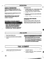
OPERATION
GENERAL CONSIDERATIONS
Damage occurs from:
Always vary capacity with regulating valve in the
discharge line. NEVER throttle flow from the suction
side.
1.
Increased vibration levels - Affects bearings, stuffing
box (or seal chamber), and mechanical seal.
2.
Increased radial thrusts - Stresses on shaft and
bearings.
3.
Heat build up - Vaporization causing rotating parts
to score or seize.
4.
Cavitation - Damage to internal surfaces of pump.
Driver may overload if the pumpage specific gravity
(density) is greater than originally assumed, or the
rated flow rate is exceeded.
Always operate the pump at or near the rated
conditions to prevent damage resulting from
cavitation or recirculation.
OPERATING UNDER FREEZING
CONDITIONS
OPERATING AT REDUCED CAPACITY
DO NOToperate pump below minimum rated
flows or with suction antior discharge va/ve
closed. These conditions may create an
explosive hazard due to vaporization of
pumpage and can quickly lead to pump failure
and physical injury. Reference Appendix ill.
Exposure to freezing conditions, while pump is idle,
could cause liquid to freeze and damage the pump.
Liquid inside pump should be drained. Liquid inside
cooling coils, if supplied, should also be drained.
SHUTDOWN
1.
Slowly close discharge valve.
2.
Shut down and lock driver to prevent accidental
rotation.
When handling hazardous arxVor to& fluids,
properpersonaip&ective
equipment should be
wom. lfpump is being drained, p@cautions must
be taken to prevent physical injury. Pumpage
must be handled and disposed of in conformance
with applicable environmental regu/ation.
.
FINAL ALIGNMENT
1.
Run the unit under actual operating conditions for a
sufficient length of time to bring the pump and
driver up to operating temperature.
2.
Check alignment while unit is still hot per alignment
procedure in Section 3.
3.
Reinstall coupling guard. Refer to coupling guard
instruction in Appendix II.
26
‘7
y.
.
,
x
.
r:-2
--
~.M.
I
L!!
.._.
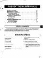
GENERAL COMMENTS
...........................
MAINTENANCE
SCHEDULE.
........................
MAINTENANCE
OF BEARINGS
.......................
Oil Lubricated Bearings
..........................
Grease Lubricated Bearings ........................
MAINTENANCE
OF SHAFT SEALS .....................
Mechanical Seals .............................
Packed Stuffing Box ............................
Dynamic Seal ...............................
IMPELLER CLEARANCE
SETTING
.. T ..................
Dial Indicator Method
...........................
Feeler Gauge Method ...........................
........................
TROUBLESHOOTING
.27
.27
.28
.28
.29
.30
-30
.30
.30
.31
-31
.32
.33
: ...
GENERAL COMMENTS
f-----t
-.
=a
A routine maintenance
program can extend the life of your pump. Well maintained
equipment
will last longer and require fewer repairs.
You should keep maintenance
records, this will help pinpoint
potential
causes of problems.
I
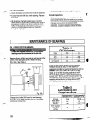
MAINTENANCE SCHEDULE
Routine Maintenance
Check for unusual noise, vibration and bearing
temperatures.
l
l
Bearing lubrication
l
Seal Monitoring
l
l
Vibration analysis
l
l
Discharge pressure
l
Temperature monitoring
Inspect pump and piping for leaks.
Check seal chamber/stuffing box leakage.
l
Mechanical Seal: Should be no leakage.
Packing: Excessive leakage requires adjustment or possible packing replacement. Refer
to Section 4: Operation for packing gland adjustment.
l
Routine Inspections
l
Check level and condition of oil through sight glass
on bearing frame.
27
-
_cl
_-.-,
_ .-_.-_v.
-I_-
_“-..-
_.
_
-.._
_,
.._
_
.
^_
~
._
_..
._
_
_.._
-
__
.
^^
_
-.
__
..__x”“a--.~.~
/
3 Month Inspections
,f@--
l
l
l
id.
l
w:
Check shaft alignment and realign if required.
Check foundation and hold-down bolts for tightness.
If pump has been left idle, check packing. Replace
if required.
Oil should be changed at least every 3 months
(2000 hours) or more often if there are any adverse
atmospheric conditions or other conditions which
might contaminate or break down the oil, or if it is
cloudy or contaminated as seen by inspection
through the sight glass.
Annual Inspections
l
Check pump capacity, pressure and Dower. If
pump perfoLnance does not satisfy iour process
requirements, and process requirements have not
changed, pump should be disassembled,
inspected, and worn parts should be replaced,
otherwise, a system inspection should be done.
MAINTENANCE OF BEARINGS
01~ LUBRICATED Bows
Pumps are shipped wlthout oil. Oil lubricated
bearings must be lubricated at the job site.
.
:f-
Remove fill plug (408H) and add oil until letiel is at the
center of the sight glass (319). Replace fill plug
(Fig. 18A). See Table 4.
I
Table 4
Oil Volumes
Frame
STX
hirx
LTX
XLT-X and Xl 7
Pints
1.0
2.6
3.0
6.0
ml
400
1250
1400
3ooo
A high quality turbine oil with rust and oxidation
inhibitors should be used. For the majority of
operational conditions, bearing temperatures will run
between 120°F (50%) and 18O’F (82%). In this
range, an oil of IS0 viscosity grade 68 at 1OO’F
(40%) is recommended. If bearing temperatures
exceed 18O’F (82%) use IS0 viscosity grade 100
with Bearing Frame cooling. See Table 5, For higher
operating temperatures, pumpage above 350°F
(1i7’C), synthetic lubrication is recommended.
Table 5
Fig. 18A
Change the oil after 200 hours for new bearings,
thereafter every 2000 operating hours or 3 months
(whichever comes first).
28
Lubricating Oil
Requirements
IS0 Grade
Approx. SSU at
1OO’F (38%)
DIN 51517
Kinem. viscosity at
1CO’FJ4O’C)
Pumpage temperature
below35O’F (177’C)
VG68
Pumpage temperawn
above SO’F (1n’c2
VGlOO
m
470
C68
Cl00
68
IO
a
NOTE: The bearing femperafure usuaiiy rises
affer regressing due to an excess suppiy of
g?ase. Temperafwee wiii refum to normal affer
pump has run and purged fhe excess from the
bearings, usually fwo to four hours.
Mobil DTE 26 300 SSU
‘&
(
For most operating conditions a lithium based mineral
oil grease of NLGI consistency No. 2 is
recommended. This grease is acceptable for bearing
temperatures of 5’F to 230°F (-15°C to 110°C).
Bearing temperatures are generally about 2O’F (18’C)
Grease lubricated bearings are pre-lubricated at
the factory. F&grease bearings every 2000 operating
hours or 3 months.
Regrease Procedure:
NOTEz When regressing there is danger of
impurifies entering fhe bearing housing. The
grease container, fhe greasing device, and
fittings, must be clean. ’
( r-
1.
Wipe dirt from grease fittings.
2.
Remove 2 grease relief plugs (408H) from bottom
of frame.
3.
Fill both grease cavities through fittings with
recommended grease until fresh grease comes
out of the relief holes. Reinstall grease relief
plugs (408H).
4.
Ensure frame seals are seated in bearina housina
and if not press in place with drains locak at the
bottom .
Never mixgreases of different wnsisfency
(NLGI 1 or 3 with NLGI 2) or different thickener.
For example never mix a iifhium base grease
wifh a poiyurea base grease.
Pumpage temperatures above 350-F (177°C) should
be lubricated by a high temperature grease. Mineral
oil greases should have oxidation stabilizers and a
consistency of NLGI 3.
NOTE: If if is necessary to change grea,se type
or consistency, fhe bearings must be removed
and the old grease removed.
MAINTENANCE OF SHAFT SEALS
-
I
MECHANICAL SEALS
When mechanical seals are furnished, a
manufacturers reference drawing is supplied with the
data package. This drawing should be kept for future
use when performing maintenance and adjusting the
seal. The seal drawing will also specify required flush
liquid and attachment points. The seal and all flush
piping must be checked and installed as needed prior
to starting the pump.
The life of a mechanical seal depends on various
factors such as cleanliness of the liquid handled and
its lubricating properties. Due to the diversity of
operating conditions it is, however, not possible to
give definite indications as to its life.
I
Starting from the innermost ring, the packing is
usually arranged as two packing rings, lantern ring,
three packing rings, followed by the split gland
(Fig. 14). Insert single packing rings by twisting as
shown in Fig. 6. Press each ring to ensure proper
compression in the stuffing box. Stagger joints 90”.
Refer to Fig. 13A, 136.
tightly and evenly tighten the gland. Excessive
tightening will result in premature failure of the
packing and shaft sleeve. After packing it must be
possible to rotate shaft by hand. Final adjustment of
packing gland is made after pump is started.
DYNAMICSEAL
Never operate the pump without liquid supplied
to mechanical seal. Running a mechanical seal
dry, even for a few seconds, can cause seal
damage and must be avoided. Physical injuv
can occur if mechanical seal fails.
PACKED STUFFING BOX
Lock out driver power to prevent accideniai
start-up and physical injuty.
The stuffing box is not packed at the factory and must
be packed properly before operation of the pump. The
packing is furnished in a box of fittings which
accompany the pump. The packing used must be
suitable for the pumpage. Make sure the stuffing box
is clean. Examine shaft-sleeve for wear or scoring,
replace if necessary.
Dynamic
Seal Components
Repeller - The dynamic repeller effectively prevents
leakage of pumpage through the stuffing box when
the pump is operating under published acceptable
conditions. Dynamic seal parts do not wear
substantially to affect operation unless the service is
particularly abrasive or corrosive. Refer to Section 6
for maintenance disassembly and repair.
Q
A static seal is used to prevent leakage when the
pump is shut down: This is’either a lip seal,
elastomeric face seal, or graphite packing. The lip
and elastomeric face seal require no maintenance
other than replacement when leakage becomes
excessive. The packing should be installed as for
stuffing box packing, and is a special type designed to
run dry, so does not require an external f&h.
a
30
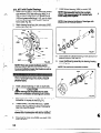
IMPELLER CLEARANCE SETTING
1
Lo&out
driver power to prevent accidental
startup and physical injury.
A change in pump performance may be noted over
time by a drop in head or flow or an increase in power
required. Performance can usually be renewed by
adjusting the impeller clearance. Two techniques are
given to set the impeller clearance, the dial indicator
method and the feeler gauge method.
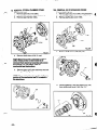
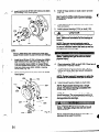
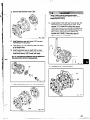
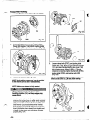
DIAL INDICATOR METHOD
I
‘-
Remove coupling guard. Refer to coupling guard
instructions Appendix II.
’
2.
Remove coupling.
3:
Set indicator so that button contacts either the shaft
end or against face of coupling (Fig. 19).
4.
Loosen jam nuts (4238) on jack bolts (371A) and
back bolts out about two turns.
Tighten each locking bolt (370C) evenly, drawing
the bearing housing (134A) towards the bearing
frame (228) until impeller contacts the casing.
Turn the shaft to ensure contact is made.
6.
Set indicator to zero and back locking bolt (370C)
out about one turn.
7.
Thread jack bolts (371A) in until they evenly contact
the bearing frame. Tighten the jack bolts evenly
(about one flat at a time) backing the bearing
housing (134A) away from the bearing frame until
the indicator shows the proper clearance per
Table 3.
8.
Evenly tighten locking bolts (37OC), then jack bolts
(371A) keeping indicator reading at proper
setting.
9.
Check shaft for free turning.
10. Replace coupling guard.
DIAL
INDICATOR
METHOD
Fig. 19
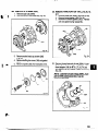
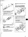
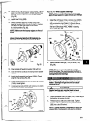
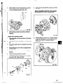
FEELER GAUGE METHOD
1. Remove coupling guard. Refer to coupling guard
instructions in Appendix II.
2.
Loosen jam nuts (4236) on jack bolts (371A) and
back bolts out about two turns (Fig. 20).
3.
Tighten locking bolts (370C) evenly, drawing
bearing housing (134A) towards frame (228) until
impeller contacts the casing. Turn shaft to
ensure contact is made.
4.
With a feeler gauge set the gap between the three
locking bolts (370C) and bearing housing (134A)
per impeller clearances in Table 3.
5.
Evenly back out bearing housing (134A) using the
three jack bolts (371 A) until it contacts the locking
bolts (370C). Evenly tighten jam nuts (4238).
6.
Check shaft for free turning.
7.
Replace coupling guard.
-
418
Feeler Gauge
c
t
32
‘,
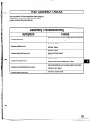
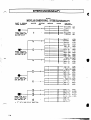
TROUBLE SHOOTING
Table 7
Troubleshoo%ng
PROBLEM
PROBABLE CAUSE
Pump
I
REMEDY
k that pump and suction
No liquid delivered.
Wrong direction of rotation.
Pump not producing rated tlow or haad.
Bearings run hot
Pump is noisy or vibrates.
‘Excessive leakage from stuffing box.
Motor requires excessive power.
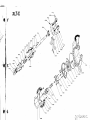
REQUIRED TOOLS.
.............................
DISASSEMBLY.
...............................
INSPECTIONS
................................
REASSEMBLY
................................
.35
.35
.46
.51
REQUIRED TOOLS
1
l
Q/l 6”, 3/4’, 7/8”, 15/l 6” Open end wrenches
l
Snap-ring pliers
l
Lifting sling
l
Allen wrenches
l
Torque wrench with sockets
l
Dial indicator
l
Micrometer
l
Impeller wrench
STX, MTX - Goulds part # A01 676A
STX, MTX, LTX, XLT-X, Xl7 Goulds part # A051 07A
l
7/i 6’ open end wrench (LTX)
l
Cleaning Agents
l
Induction bearing heater
l
Feeler gauges
l
Brass drift punch
l
Spanner wrench
,
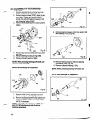
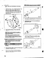
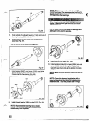
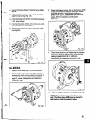
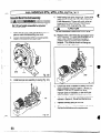
DISASSEMBLY
Pump components can be heavy. Proper
methods of lifting must be employed to avoid
physical injury and/or equipment damage.
Steel toed shoes must be worn at all; times.
The 3796 may hand/e hazardous and/or toxic
fluids. Proper personal protective equipment
should be worn. Precautions must be taken to
prevent physical injury. Pumpage must be
handled and disposed of in conformance with
applicable Environmental
Regulations.
F4
NOTE: Before disassembling
the pump for
overhaul, ensure all replacement parts are
available.
Lock out power supply to driver motcw to
prevent accidental startup and physical injury.
1.
Shut off all valves controlling flow to and from pump.
Operator must be aware of pumpa e snd safety
precautions to prevent physical in Pury.
2.
Drain liquid from piping, flush pump if necessary.
3.
Disconnect all auxiliary piping and tubing.
4.
Remove coupling guard. Refer to Coupling Guard
Installation and Disassembly Section in
Appendix 2.
35
.
-
_
,_
-
._
.,
..,___
“.-
.
/r”-.
5.
Disconnect Coupling.
11. Remove back pull-out assembly from casing (100).
Tighten jack screws (418) evenly to remove back
pull-out assembly (Fig. 23).
6.
Remove coupling guard pump endplate.
7.
if oil lubricated, drain oil from bearing frame by
removing bearing frame drain plug (408A).
Replace plug after oil is drained. Remove oil
reservoir, if equipped (Fig. 21).
NOTE: Penetrating oil can be used if adapter to
casing joint is excessively corroded.
NOTE: Remove and then mark shims ftom
under frame foot. Save for reassembly.
Never remove the back pull-out assembly
unassisted, physical iqwy can occur.
12. Remove casing gasket (351) and discard. (Replace
with new gasket during reassembly.)
13. Remove jack screws (418).
NOTE: Casing gasket (357) may partially adhere
to casing due to binders and adhesives in the
gasket material. Clean all gasket surfaces.
NOTE: Oil ana/ysis should be part of a
preventive maintenance program, and is helpful
to determine cause of a failure. Save oil in a
clean container for inspection.
8.
Place sling from hoist through frame adapter (108)
or frame (228A) for STX (Fig. 22).
9.
Remove bearing frame foot hold down bolts (37OF).
10. Remove casing bolts (370).
14. Move back pull-out assembly to clean work bench.
15. Support frame adapter (108) securely to
workbench.
Fig. 22
Never apply heat to remove parts. Use of heat
may cause an explosion due to trapped fluid,
resulting in severe physical injury and property
damage.
Fig. 24
36
_’
..,_
._
-.
-.__..
-r_.
NOTE: FOR ALL MODELS
NO775 Blue and s&be shaft for relocating
coupling hub during reassembly.
I
\
If the impeller cannot be removed by the previous
methods, cut the shaft between the gland and the
frame, remove the impeller, stuffing box cover,
gland, sleeve and shaft end as a unit. Do not use
heat.
16. Remove coupling hub (Fig. 24).
Removal of Impeller
Never apply heat to remove impeller. Use of
heat may cause an explosion due to trapped
fluid, resulting in seven3 physical Injury and
property damage.
Wear heavy work gloves when handling
impeler (101) as sharp edges may cause
.. physkalinjuty.
,P-
Two special features have been incorporated into the
XLT design to ease maintenance problems and
preclude the temptation to apply heat to stubborn parts.
1. A plug has been added to the nose of the XLT
impellers. It is sealed with a teflon gasket
Removing the plug relieves any pressure
between the impeller and the shaft and
provides means to introduce penetrating oil to
the threads to ease impeller removal.
2. A hexagonal nut is cast on the impeller hub so a
socket wrench can be used to assist removal.
17. Recommended removal procedure is as follows:
STX, MTX, LTX: Remove impeller (101) from shaft
(122). Slide Goulds shaft wrench (A051 07A) over
shaft (122) and key. Rotate impeller clockwise
(viewed from impeller end of shaft) raising wrench
off work surface. Quickly turn impeller (101)
counterclockwise (viewed from impeller end of
shaft) impacting wrench handle on workbench or
solid block until impeller (101) loosens (Fig. 25).
I
I
101
Fig. 25
Fia. 25A
18. Remove impeller O-ring (412A) and discard
(Fig. 26).
XLT-X & Xl 7: Remove plug (458Y) from front of
impeller (101) and discard teflon gasket (428D)
(Fig. 25A). Spray penetrating oil through plug
hole into cavity at end of shaft. Wait 15 minutes.
Rotate shaft several times while waiting to
distribute oil. Proceed to remove impeller from
shaft as described above for SIX, MlX, and LTX.
If impeller cannot be loosened after several tries,
place socket wrench over cast nut on impeller
hub and turn impeller counterclockwise (viewed
from impeller end of shaft). Be sure impeller
wrench is resting on workbench or solid block and
the powerend is secure on workbench. It is
further recommended that the frame foot (241) be
clamped to the workbench when using this
method to remove the impeller.
37
1
/
lg.
REMOVAL OF SEAL CHAMBER COVER
(Mechanical Seal)
1. Remove gland stud nuts (355).
2. Remove seal chamber stud nuts (370H).
3. Remove seal chamber (184).
.,* i:,:
19+
REMOVAL OF STUFFING BOX COVER
(Packed Box) (Fig, 29)
1. Remove gland stud nuts (355), and gland(107).
2. Remove stuffing box cover stud nuts (370H).
3. Remove stuffing box cover (184).
Fig. 29
4. Remove shaft sleeve (126) (Fig. 30).
4.
Remove shaft sleeve (128), if used.
NOTE Mechanical seai is attached to sleeve
(726”. Rotary potion of seal needs to be
.
removed from sleeve by loosening set screws
and sliding it off the sleeve. Refer to
mechanical seal instructions.
126
5. Remove gland (107) with stationary seat and
O-ring (360Q) (Fig. 28).
NOTE: Be careful not to damage the stationary
portion of the mechanical seal. It is seated in
the g/and bore.
/
3
lg. 30
5. Remove packing (106) and lantern ring (105)
from stuffing box cover (184) (Fig. 31).
126
38
Fig. 28
M’
!
196. REMOVAL OF DYNAMIC SEAL...
1. Remove stud nuts (370H).
2. Remove dynamic seal assembly (Fig. 32).
20. REMOVE FRAME ADAPTER - MTX, LTX, XLT-X,
x17
1. Remove dowel pins (4698), and bolts (3706).
2. Remove frame adapter (108) (Fig. 34).
3. Remove and discard gasket (3600). Replace
with new gasket during reassembly.
v
3. Remove socket head cap screws (266)
(Fig. 33).
4. Remove stuffing box cover (184) and gasket
(264) -
5. Remove repeller (262) from backplate (444).
. ..- .- - __.“-_
IV’
3708
Fig. 34
21. Remove inboard labyrinth oil seal (333A), it is an
O-Ring fit into the bearing frame (228A) for STX,
frame adapter (108) for MTX, LTX, XL.T-X and
Xl 7. Remove O-rings (497H), (497J) if necessary
(Fig. 35).
.:“;
NOTE: Labyrinth oil seal o-rings (497H, .I) are
,‘part of 3136 maintenance kits or can be
obtained sepamtely
Fig. 33
=A.
DISASSEMBLY
OF POWER
END - STX, MTX
1. Remove clamp screws (370C). Back off jam
nuts (423). Tighten jack screws (3700)
evenly, this will start bearing housing (134)
out of bearing frame (22819) (Fig. 36).
2. Remove the shaft assembly from the bearing
frame (228A).
7. Remove outboard labyrinth seal (332A) from
bearing housing (134). Remove O-rings
(497F), (497G) if necessary (Fig. 39).
NOTE: Labyrinth oil seal O-rings (497F, G) are
part of 3196 maintenance kits or can be
obtained separately
Fig. 36
3. Remove jack screws (370D) with nuts (423)
(Fig. 37).
4. Remove bearing housing O-ring (469).
5. Remove outboard bearing retaining snap ring
(316A).
NOTE: Sna ring cannot be removed from the
shaft until g earings are removed.
Fig. 39
8. Remove bearing locknut (136) and bearing lock
washer (382) (Fig. 40).
9. Remove inboard bearing (168A).
10. Remove outboard bearing (112A).
NOTE: When pressing bearings off shaft, use
force on inner race only.
NOTE: Save bearings
for inspection.
166A
6. Remove bearing housing (134) from shaft (122)
with bearings (112A, 168A) (Fig. 38).
Fig. 40
t
316A
Fig. 38
40
-_ -_____._I”-l-___.._l-._
“_
-
228. DISASSEMBLY OF POWER END - LTX
1. Remove clamp screws (37OC). Back off jam
nuts (423). Tighten jack screws (3700)
evenly, this will start bearing housing (134)
out of bearing frame (228A) (Fig. 41).
2. Remove shaft assembly from bearing frame
(228A).
7. Remove inboard bearing (168A) (Fig. 43B).
8. Remove bearing locknut (136) and bearing
lockwasher (382).
9.
Remove outboard bearings (112A). Remove
clamp ring (2538)
When pressing bearings
force on inner race on/y.
NOTE:
NOTE: Save bearings
reuse bearings.
off shaft, use
for inspection.
Do not
NOTE: 50 not remove oil ffinger (248.A) unless it
is damaged.
3. Remove jack screws (370D) with nuts (423)
(Fig. 42).
4. Remove clamp ring screws (236A). Separate
clamp ring (2536) from bearing housing (134)
NOTE: Clamp ring cannot be removed from the
shaft until bearings are removed.
Fig. 43E
10. Remove outboard labyrinth seal (332A) from
bearing housing (134). Remove O-rings
(497f3 (497G) if necessary (Fig. 44).
NOTE: Labyrinth oil seal O-rings (497F, G) are
part of 3196 maintenance kits of can be
obtained separately
Fia. 42
5. Remove bearing housing (134) from shaft (122)
with bearings (112A, 168A) (Fig. 43A).
6. Remove bearing housing O-ring (469).
Fig. 43A
22~. DISASSEMBLY OF THE POWER END XLT-X, Xl 7
1. Remove bearing frame to frame foot bolts
(37OF) and frame foot (241) (Fig. 45).
2. Remove clamp screws (370C). Back off jam
nuts (423). Tighten jack screws (3700)
evenly, this will start bearing housing (134)
out of bearing frame (228A),
3. Remove shaft assembly from bearing frame
(228A).
i
Fia. 47
9.
Remove bearing housing (134) from shaft (122)
with bearing (112A) (Fig. 48).
37oc
Fig. 45
4. Remove jack screws (370D) with nuts (423)
(Fig. 46).
5. Remove bearing housing O-ring (469).
6. Remove inboard bearing (168A).
NOTE: When pressing bearfngs off shaft, use
force on inner race only.
NOTE: Save bearings
Fig. 48
112A
10. Remove bearing locknut (136) and bearing
lockwasher (382) (Fig. 49).
11. Remove outboard bearing (112A).
for inspection.
NOTE: When pressing bearings ofif shaff, use
force on inner race only.
NOTE: Save bearings
for inspection.
Fig. 46
7. Remove bolts (371 C), bearing end cover
(109A) and gasket (360C) (Fig. 47).
8. Remove outboard labyrinth seal (332A) from
end cover (109A). Remove O-rings (497F),
(4976) if necessary.
NOTE: Labyrinth oil seal O-rings (497F, G) are
part of 3196 maintenance kits or can be
obtained separately
‘3432
Fig. 4s
42
-.. --_-
.-----.---1
.
nD.
DISASSEMBLY
OF POWER END STX, MlX with Duplex Bearings
1, Remove clamp screws (37OC). Back off jam
nuts (423). Tighten jack screws (370D)
evenly, this will start bearing housing (134)
out of bearing frame (228A) (Fig. 50).
2. Remove shaft assembly from bearing frame
(228A).
112A
Fig. 52
7. Remove inboard bearing (166A) (Fig. 53).
8. Remove bearing locknut (136) and bearing
lo&washer (382).
9. Remove outboard bearings (112A).
NOTE: When pressing bearings offshaft,
force on inner race oniy.
NOTE: Save bearings
3. Remove jack screws (370D) with nuts (423)
(Fig. 51).
4. Remove bearing housing O-ring (469).
5. Remove clamp ring screws (236A). Separate
clamp ring (2538) from bearing housing (134).
NOTE= C/amp ring cannot be removed tram the
shafi until bearings are removed.
use
for inspection.
1
10. Remove outboard labyrinth seal (332A) from
bearing housing (134). Remove O-rings
(497F), (497G) if necessary (Fig. !j4).
NOTE: Labyrinth oil seal O-rings (4gTF, G) are
part of 3196 maintenance kits or can be
obtained separs tely
423
Fig. 51
6. Remove bearing housing (134) from shaft (122)
with bearings (112A, 168A) (Fig. 52).
ZE. DlSASSEM6k.Y OF POWER END XLT-X, Xl 7 with Duplex Bearings
1. Remove bearing frame to frame foot bolts
(37OF) and frame foot (241) {Fig. 55).
2. Remove clamp screws (370C). Back off jam
nuts (423). Tighten jack screws (3700)
evenly, this will start bearing housing (134)
out of bearing frame (228A).
3. Remove shaft assembly from bearing frame
(228A).
8. Remove outboard labyrinth seal (332A) from
end cover (109A). Remove O-rings (497F),
(497G) if necessary.
NOTE: labyrinth oil seal O-rings (497F, G) are
part of 3196 maintenance &its or can be
obtainedseparstely
j
9. Remove bearing housing (134) from shaft (122)
with bearings (112A) (Fig. 58).
Fig. 55
4. Remove jack screws (370D) with nuts (423)
(Fig. 56).
5. Remove bearing housing O-ring (469).
6. Remove inboard bearing (168A).
NOTE: When pressing bearings off shaft, use .
force on inner race on/y.
NOTE: Save bearings
10. Remove bearing locknut (136) and bearing
lockwasher (382) (Fig. 59).
11. Remove outboard bearing (112A).
for inspection.
NOTE: When pressing bearings off the shaft,
use force on the inner race only.
NOTE: Save bearings
for inspection.
Fig. 56
7. Remove bolts (371 C), end cover (109A) and
gasket (360C) (Fig. 57).
Fig. 59
44
-_.--.-
._._-_
,_,.._.
I)
pi
ALL MODELS
I
23. DISASSEMBLY OF BEARING FRAME
1. Remove oil fill plug (113A), oil drain plug
(408A), sight glass (319), sight oiler plug
(408J), four (4) oil mist/grease connection
plugs (408H), and oil cooler inlet and outlet
plugs (408L, 408M) from bearing frame
(228A).
2. MTX, LTX: Remove bearing frame
foot-to-frame bolts (37OF), and frame foot
(241)
3. Proceed to Parts Inspection.
-
113A
45
l_,.___.c_I.-._
-._--__,_
__
.,..
_
.
_.
”
^
.
_.
-.-
L,..a.--*~~-~
I
INSPECTIONS
The Model 3196 parts must be inspected to the
following criteria before they are reassembled to
insure the pump will run properly. Any part not
meeting the required criteria should be replaced.
3.
\
Inspect leading and trailing edges of the vanes for
pitting, and erosion or corrosion damage.
(Area ‘c” in Fig. 62.).
I
C
NOTE: Clean parts in solvent to remove oil,
grease or dirt. Protect machined surfaces
against damage during cleaning.
a
Casing
b
The casing (100) should be inspected for excessive
wear or pitting. It should be repaired or replaced if it
exceeds the following criteria (Fig. 61).
1.
Localized wear or grooving greater than l/8 in.
(3.2 mm) deep.
2.
Pitting greater than l/8 in. (3.2 mm) deep.
3.
Inspect case gasket seat surface for irregularities.
Fig. 62
100
Frame Adapter
1.
Check frame adapter (108) for cracks or excessive
corrosion damage. Replace if any of these
conditions exist (Fig. 63).
2.
Make sure gasket surface is clean.
Fig. 61
Impeller
1.
Inspect impeller (101) vanes for damage. Replace if
grooved deeper that l/l 6 in. (1.6 mm) or if worn
evenly more than l/32 in. (0.8 mm).
(Area “a’ in Fig. 62)
2.
Inspect pumpout vanes for damage. Replace if worn
more than l/32 in. (0.8 mm).
(Area “b” in Fig. 62)
t
46
-
4,
Shaft and Sleeve
1.
Check bearing fits. If any are outside the tolerance
in Table 8, replace the shaft (122) (Fig. 64A).
2.
Check shaft straightness. Replace shaft if runout
exceeds values in Table 12.
3.
Check shaft and sleeve (126) surface for grooves,
pitting. Replace if any are found (Fig. 646).
-
I
Inspect inboard bearing bore according to Table 2.
Fig. 64A
-
241
Fig. 648
Fig. 66
Bearing Frame
1.
Visually inspect bearing frame (228) and frame foot
(241) for cracks. Check frame inside surfaces for
rust, scale or debris. Remove all loose and
foreign material (Fig. 6666).
2.
Make sure all lubrication passages are clear.
3.
If frame has been exposed to pumpage inspect for
corrosion or pitting.
.
Dynamic Seal Repeller
1.
inspect dynamic seal repeller (262) vanes for
damage. Replace if grooved deeper than 1/16 in.
(1.6 mm) or if worn evenly more than i/32 in.
(0.8 mm) (Fig. 67).
2.
inspect sleeve surface for grooves, pitting or other
damage. Replace if damaged.
_* :
Fig. 69
k I
t I
dFig
;1
/L-
. 67
Seal Chamber/Stuffing Box Cover and
Dynamic Segl Backplate
1.
Make sure seal chamber/stuffing box cover (184)
and dynamic seal backplate (444) gasket surface
is clean, at adapter face (Fig. 68, 69, 70).
2.
Replace if any pitting or wear greater than l/8 in.
(3.2 mm) deep.
a
Bearings
1.
Ball bearings (112A, 168A) should be inspected for
contamination and damage. The condition of the
bearings will provide useful information on
operating conditions in the bearing frame.
Lubricant condition and residue should be noted,
oil analysis is often helpful. Bearing damage
should be investigated to determine cause. If
cause is not normal wear, it should be corrected
before pump is returned to service.,
DO NOT RE-USE
48
_ .___---_
BEARINGS.
Bearing Housing
1.
Inspect-bearing housing (134) bore according to
Table 8. Replace if dimensions exceed Table 8
values.
2.
Visually inspect for cracks and pits.
STX, MTX - Snap ring groove must not be
cracked (Fig. 71).
LTX - Grooves and holes must be clear (Fig. 72).
XLT-X, Xl 7 - Gasket surface must be clean (Fig. 73).
Fig. 73
Labyrinth Seals
1.
Labyrinth seal (332A. 333A) O-rings should be
inspected for cuts and cracks. Replace as
needed.
Fig. 71
49
Table 8
3196 Bearing Fits & Tolerances
STX
Shaft0.D.
Inboard
sealing I.D.
Inboard
FrameiD.
Inboard
according to ABEC I standard
MTX
in. (mm)
1.3785
(35.013)
1.3781
(35.002)
0.0010 (0.025)tight
0.0001 (0.002)tight
1.7722
(45.013)
1.7718
(45.002)
O.OOlO(0.025)tight
0.0001 (0.002)tight
1.3780
w.@w
1.3775
WQW
1.7717
W.~)
1.7712
WQW
;2%)
2.8353
(72.019)
0.0012(0.032)ioose
o.oooo
(O.wo)
loose
Searing0.D.
Inboard
Outboard
Ekaringl.D.
Housing I.D.
OUtbOard
o.woo(O.ooo)
loose
3.9370
(roo.000)
2.6341
(ii?&
1.1815
(30.011)
1.1812
(30.002)
o.ooo8 (0.021) tight
0.0001 (0.002)tight
1.1811
wow
1.1807
lR22
(45.013)
1.7718
(45.002)
0.0010(0.025)tight
0.0001 (0.002)tight
1.7717
(45.000)
1.7712
(29.990)
WQW
(k2E)
2.8353
(72.019)
0.0012(0.032)loose
0.cKHIO(0.000) loose
;2z)
Ekaring0.D.
Outboard
3.9370
(loo.ooo)
3.9379
(100.022)
0.0015(0.037)l00se
;zEz)
v-v
Shaft0.D.
OUtbOWCl
in. (mm)
2.8341
(71.987)
3.9370
(lOO.cOO)
3.9379
(100.022)
0.co15(0.037) loose
o.OOOO(o.OOO)loose
3.9370
(loo.ooo)
3.9364
(99.985)
LlX
in. (mm)
2.1660
(55.015)
2.1655
(55.002)
XLT-X,X17
in. (mm)
2.5597
(65.015)
2.5592
(65.002)
0.0012(0.030)tight
o.ooo1 (0.002) tight
o.Ot112 (0.030)tight
0.0001 (0.002)tight
. 2.5591
WJJW
2.1654
wow
2.1648
(ii%,
w.Qw
4.7244
(120.000)
4.7253
wO.022)
0.0015(0.037)l00ss
o.woo(0.ooo)
loose
4.7244
(120.ooo)
4.7238
(119.985)
(22,
1.9666
(50.002)
O.WlO (0.025)tight
0.0001(0.0.002)tight
(ii=)
1.9680
(49.988)
4.3307
(llO.OQO)
4.3316
(110.022)
0.0015(0.037)l00se
0.0000 (O.O&l)loose
4.3307
(110.000)
4.3301
(109.995)
.
5.5118
(14o.wo)
5.5128
(140.025)
0.0017(0.043)kme
o.oow(Omo)loose
5.5118
(14o.cQO)
5.5111
(139.982)
2.5597
(65.015)
2.5592
(65.002)
0.0012(0.030)tight
o.ooo1 (0.002)tiQht
2.5591
yg)
(&985)
5.5118
(140.000)
5.5128
(140.025)
0.0017 (0.043)loose
0.0000(0.000) loose
5.5118
(140.ooo)
5.5111
(139.982)
Q
50
REASSEMBLY
Refer to Table 9 for torque values while reassembling
pump.
Table 9
Bolt Torque Table
LOCATION
LUBRICATED
6’STX
8’STX
CASING BOLTS (370)
Mix, LTX
XLT-X Xl 7
FRAME - TO - ADAPTER BOLTS (3708)
BEARING CLAMP RING BOLTS
_
srxMTx
w34
Duplex Bearing Only
BEARING END COVER BOLTS
(371 C)
YNAMIC SEAL CAP SCREWS (265
THREADS
30 Fr-LBS (40 Nm)
Fr-LBS
n=LBS
FT-LBS
FT-LBS
(60 Nm)
(40 Nftl)
(60 Nm)
(So N.m)
LlX
20 El--LBS
30 FT-LBS
30 Fr-LBS
20 Fr-LBs
10 INLBs
55 IN-LB
(27
(40
(40
(27
(1.1
(6.2
XLT-X Xl 7
9 IT-LBS
(12 km)
12 l=T-l.BS (16 Nm)
55 INUS (6.2 Nn)
SFT-l.B!Z (12 km)
63 IN-LBS (9.4 Nm)
12 FT-LBS (16 Nm)
STX, MTX LTX
XLT-x, Xl 7
Refer to Table IO for shaft end play while reassembling
N-m)
Nn)
Nal)
Nal)
N.m)
Nm)
DRY THREADS
45
30
46
45
pump.
30 Fr-LBS (40 Nm)
17 IN-LBS (1.9 N-m)
63 IN-LBS (9.4 Nm)
Table 12
3196 Shaft Runout Tolerances
SleeveFit
in. (mm)
WtiSleeve
LessSleeve
Note: Bearing type is based on SKF/MRC
ky;;bly
.OOl (.026)
.cO2(.051)
designation.
of Rotating Element and Bearing
STX,IUTX
NOTE: Make sure that threads are clean and
apply thread sealant to pipe threads and fittings.
1.
Install oil fill plug (113A), oil drain plug (408A), sight
window (319), sight oiler plug (408J), 4 oil mist
connection plugs (408H) or grease fittings (193)
and relief plugs (113) and oil cooler inlet and
outlet plugs (408L, 408M) in bearing frame (228).
(Fig. 74)
2.
Attach bearing frame foot (241) with bolts (37OF).
Hand tighten.
52
CouplingFit
in. (mm)
,001 (.026)
.OOl (.026)
3.
Install outboard bearing (112A) on shaft (122)
(Fig. 75).
NOTE: Regreaseabie bearing has a single
shield. The outboard bearing is installed w!th
shield toward impeller.
d
NOTE: There are several methods used to
install bearings. The recommended method is
to use an induction heater that heats as we!! as
dem.agnet!zes the bearings.
Wear insulated gloves when using a beating
heater. Bearings will get hot and can cause
physica! injury.
4.
Place lo&washer (382) on shaft (122). Place tang of
lockwasher in keyway of shaft
5.
Thread locknut (136) onto shaft (122). Tighten
locknut until snug. Bend any tang of lockwasher
into a slot of locknut.
NOTE: 77ghten locknut if necessary to align the .
closest tab of lo&washer with slot on lo&rut.
6.
Place bearing retaining ring (361 A) over shaft (122),
flat side facing bearing.
7.
Install inboard bearing (168A) on shaft (122).
-,
8.
Install new O-ring (496) (Fig. 76).
9.
Coat outside of outboard bearing (11:~) and
bearing housing (134) bore with oil.
10. Install bearing housing (134) onto shaft/bearing
assembly.
NOTE: Do not force assembly
together.
11. Insert retaining ring (361 A) into groove in housing
(134) bore. Check shaft for free turning.
NOTE.. The space between the ends of retaining
r!ng should be located in the oil return groove
so as not to obstruct oil flow.
12. Install outboard labyrinth oil seal (332A) into
bearing housing (134). It is an O-ring fit. Position
the labyrinth seal drain slots at the bottom
(6 o’clock) position.
FfE
.
Make sure the keyway edges are free of
NOTE: Cover the keyway lengthwise with a
piece of elect&a! tape prior to instarning the
Iabyrinth sea!. This w!!! protect the tLrings.
NOTE: Regreaseabie bearing has a sin ie
~_shield.. The inboard bearing is instaile B with
shieid away from impeller.
NOTE: There are several methods used to
install bearings, Ttre recommended method is
to use an induction heater that heats as we!! as
demagnetizes the bearings.
Wear insulated gloves when using a beartng
heater. Bearings will get hot and can cause
physica! iniury.
NOTE: Coat internal surfaces of bearings
iubr!cant to be used in service.
with
Fin. 76
13. Coat outside of bearing housing (134) with oil
(Fig. 77).
14. Coat all internal surfaces of bearing fra.me (228A)
with oil.
168A
15. Install shaft assembly into frame (228A.). Check
shaft for free turning.
16. Install clamping bolts (370C) into bearing housing
(134). Hand tighten,
136
\
Fig. 75
53
Id L,.
17. Install jacking bolts (370D) with locking nuts (423)
into housing (134). Hand tighten.
3.
w
Install oil Ringer (248A) on shaft (122) if removed
(Fig. 79).
NOTE: The oil flinger is a press tit onto shaft.
Use a driver of proper size to prevent damage
to oii fifnger.
4.
Place bearing clamp ring (2538) over shaft (122).
Note orientation.
5.
Install outboard bearings (112A) on shaft (122).
1A
CAUTION
I
The LTX uses duplex bearings mounted back to
back Make sure orientation of the bearings is
Correct
NOTE: There are several methods used to
install bearings, The recommended method is
to use an induction heater that heafs as well as
demagnetizes the bearings.
,,I
,,
Fig. 77
(j
LTX
NOTE: Make sure that threads are clean and
apply thread sealant to pipe threads and tittings.
1.
2.
Install the oil fill plug (113A), oil drain plug (408A),
sight window (319), sight oiler plug,(408J), 4 oil
mist connection plugs (408H) or grease fittings
(193) and grease relief plugs (113), and oil cooler
inlet and outlet plugs (408L. 408M) in bearing
frame (228) (Fig. 78).
Wear insulated gloves when using a bearing
heater. Bearings will get hot and can cause
physical injury.
6.
Place Imasher
(382) on shaft (122). Place tang of
lockwasher in keyway of shaft.
7.
Thread locknut (136) onto shaft (122). Tighten
locknut until snug. Bend any tang of lockwasher
(382) into a slot of locknut.
Attach bearing frame foot (241) with bolts (37OF).
Hand tighten.
-
NOTE: Rghten locknut if necessa+ to align the
closest tab of lockwasher with slot
. onj locknut.
113A
8.
,
Install inboard bearing (168A) on shaft (122).
NOTE: Regreaseabie bearing has a sing/e
shield. The inboard bearing is installed with
shield away from impeller.
NOTE: There are severai methods used to
install bearings, The necommendetd method is
to use an induction heater that heats as weif as
demagnetizes the bearings.
Wear insulated gloves when using a bearing
heater. Bearings wbl get hot and can cause
physical injury.
NOTE: Coat infernal surfaces of bearings
iubricartt to be used in service.
f-.
54
wifh
tf&E:
Make sure the keyway edges are free of
.
NOTE: Cover the keyway IerFgthwise with a
piece of ehzctrical tape prior to installing the
Isbyrinth seal. This will protect the O-rings.
,
FiQ. 79
9.
Coat outside of outboard bearing (112A) and
bearing housing (134A) bore with oil.
10. Install bearing housing (134) onto shaft/bearing
assembly (Pig. 80).
NOTE: Do not force assembly
together.
’
Fig. 81
14. Coat outside of bearing housing (134A) with oil.
15. Coat all internal surfaces of bearing frame (228)
with oil.
16. Install shaft assembly into frame (228A). Check
shaft for free turning.
17. Install clamping bolts (370C) into bearing housing
(134A). Hand tighten.
18. Install jacking bolts (370D) with locking nuts (423)
into housing (134A). Hand tighten.
Fia. 80
11. Install clamp ring bolts (236A). Check shaft for free
turning. Refer to Table 9 for bolt torque values
(Fig. 81).
I A
CAUTION
77ghten clamp ring bolts (236.4) in a criss cross
pattern.
I
12. Install new O-ring (496).
13. Install outboard labyrinth oil seal (332A) into
bearing housing (134). It is an O-ring fit. Position
the labyrinth seal drain slots at the bottom
(6 o’clock) position.
..-- -.,-.“..-l---m.- i+r~..Le--.----__I__.P...-~-.s--?--.~,~~
Fig. 82
55
_- .,_ .- ~ _-___....I ..
~
NOTE: Rghten locknut if necessary to align the
closest tab of lockwasher with slot on locknut.
XLT-X,X17
NOTE: Make sure ‘that threads are clean and
appiy thread sealant to pipe threads and fittings.
Install oil fill plug (113A), oil drain plug (408A), sight
glass (319), sight oiler plug (408J), 4 oil mist
connection plugs (408H), or grease fittings (193)
and grease relief plugs (113). and oil cooler inlet
and outlet plugs (408L, 408M) in bearing frame
(228A) (Fig. 83).
1.
Fig. 84
5.
Coat outside of outboard bearing (112A) and bore of
bearing housing (134) with oil.
6.
Install bearing housing (134) onto shaft/bearing
assembly (Fig. 85).
NOTE: Do not force assembly
I:
2.
together.
Install outboard bearing (112A) on shaft (122)
(Fig. 84).
NOTE: Regmaseable bearing has a single
shield. The outboard bearing is instailed with
shield toward impeller.
NOTE: There are several methods used to
install bearings, The recommended method is
to use an induction heater that heats as well as
demagne tires the bearings.
7.
Install gasket (36OC), end cover (lOgA), bolts
(371 C). Refer to Table 9 for bolt toroue values.
Check shaft for free turning.
Wear Insulated gloves when using a bearing
heater. Bearings will get hot and can cause
physical injury.
.
Shaft (122) may be heavy. Use care when
handling.
:p”z,
3.
Place lock-washer (382) on shaft (122). Place tang of
lockwasher in keyway of shaft.
4.
Thread locknut (136) onto shaft (122). Tighten
locknut until snug. Bend any tang of lockwasher
(382) into a slot of locknut.
56
Fig. 86
8.
install inboard bearing (169A) on shaft (122)
(fig. 87).
NOTE: Regreaseabie bearing has a single
shield. The inboard bearing is installed with
shield away from impeller.
e
NOTE: There are several methods used to
install bearings, The recommended method is
to use an induction heater that heats as wei/ as
demagnetizes the bearings.
496
324
I
Wear insulated gloves when using a bearing
heater. Bearings will get hot and can cause
physical injury.
11. Coat outside of bearing housing (134) ‘with oil.
NOTE: Coat internal surfaces of bearings
lubricant to be used in service.
12. Coat all internal surfaces of bearing frame (228A)
with oil.
with
109A
Fig. 88
13. Install shaft assembly into frame (228A,). Check
shaft for free turning (Fig. 89).
14. Install clamping bolts (370C) into bearing housing
(134). Hand tighten.
15. dnstall jacking bolts (370D) with locking nuts (423)
into housing (134). Hand tighten.
16. Attach bearing frame foot (241) with bolts (37OF).
Hand tighten.
9.
Install new O-ring (496) (Fig. 88).
10. lnstali outboard labyrinth oil seal (332A) into end
cover (109A). It is an O-ring fit. Position the
labyrinth seal drain slots at the bottom 6 o’clock
position (Fig. 88).
:fO’
.
Make sure the keyway edges are free of
NOTE: Cover the keyway lengthwise with a
piece of electrical tape prior to installing the
labyrinth seal. 73is will protect the O-rings.
Fig. 89
7.
sm, MTX with Duplex Bearings
1. Install the oil fill plug (113A), oil drain
plug (408A),
sight window (319),-sight oiler plug (468Jj, 4 oil mist connection plugs (408H), or grease fittings
(193) and grease relief plugs (113), and oil cooler
inlet and outlet plugs (408L, 408M) in bearing
frame (228) (Fig. 90).
2.
Install inboard bearing (168A) on shaft (122).
NOTE: Regmaseabie bearing has a single
shield. The inboard bearing is installed with
shield away from impeller.
iy
\_
NOTE: Coat internal surfaces of bearings with
lubricant to be used in service.
Attach bearing frame foot (241) with bolts (37OF).
Hand tighten (Fig. 90).
Fig. 91
\136
-
90
-_---
-
Tner8 ar8 Several methods used to
install beatings, The recommended method is
to use an induction heater that heats as well as
demagnetizes the bearings.
NOTE:
8.
Coat outside of outboard bearing (112A) and bore of
bearing housing (134) with oil.
9.
Lower shaft/bearing assembly into bearing housing
(134) (Fig. 92).
241
NOTE: Do not force assembly
Wear insulated groves when using a Laring
heater. Bearings will get hot and can cause
physica/ injury.
together.
134
/
3.
Install outboard bearings (112A) on shaft (122).
[A
CAUTION
Duplex bearings are mounted back to.back.
Make sure orientation of bearings are correct.
I
Fig. 92
4.
Place lockwasher (382) on shaft (122). Place tang of
lockwasher in keyway of shaft (Fig. 91).
5.
Thread locknut (136) onto shaft (122). Tighten
locknut until snug. Bend any tang of lo&washer
(382) into a slot of locknut.
NOTE: 77ghten locknut if necessary to align the
closest tab of lo&washer
with slot on locknut.
6.
Place bearing clamp ring (2538) over shaft (122).
Note orientation.
58
_.__.___-_-.-__-- -- - --
.
...
-
10. Install clamp ring (2536) with bolts (236A). Tighten
bolts in a crisscross pattern. Check shaft for free
turning. Refer to Table 9 for-bolt torque values
(Fig. 93).
XLT-X,Xl7 with Duplex Bearings
11. Install new O-ring (496).
1.
NOTE? Make sure that threads are clean and
apply thread sea/ant to pipe threads and fittings.
Install the oil fill plug (113A), oil drain plug (408A),
sight window (319) sight oiler plug (40&j), 4 oil
mist connection plugs (408H), or grease fittings
(193) and grease relief plugs (113). and oil cooler
inlet and outlet plugs (408L, 408M) in bearing
frame (228) (Fig. 95).
12. Install outboard labyrinth oil seal (332A) into
bearing housing (134). It is an O-ring fit. Position
the labyrinth seal drain slots at the bottom
6 o’clock position (Fig. 93).
NOTE: Make sure the keyway edges are f&e of
burrs.
NOTE: Cover the keyway Iengthwise with a
piece of &ctrical
tape prior to installing the
labyiinth seal. This will protect the O-rings.
408M
\
2.
Fig. 93
13. Coat outs/de of bearing housing (134) with oil.
m0
Install outboard bearings (112A) on shaft (122)
(Fig. 96).
NOTE: There are several methods used to
ins&M bearings, The recommended method is
to use an induction heater that heats as well as
demagnetizes the bearings.
14. Coat all internal surfaces of bearing frame (226A)
with oil.
15. Install shaft assembly into frame (228A). Check
shaft for free turning (Fig. 94).
Wear insulated gloves when using a &earing
heater. Bearings will get hot and can cause
physical injury
16. Install clamping bolts (370C) into bearing housing
(134A). Hand tighten.
17. Install jacking bolts (370D) with locking nuts (423)
into housing (134A). Hand tighten.
I A
CAUTION
I
Duplex bearings are mounted back to back.
Make sure orientation of bearings are correct.
3.
Place lockwasher (382) on shaft (122). Place tang of
lockwasher in keyway of shaft.
4.
Thread locknut (136) onto shaft (122). Tighten
locknut until snug. Bend any tang of lockwasher
(382) into a slot of locknut.
NOTE: Tighten locknut if necessary to ai@n the
closest tab of lo&washer with slot on Locknut.
Fig. 94
__._._-._
_
59
_
NOTE: There are several methods used to
instail bearings, The recommended method is
to use an induction heater that heats as wefl as
demagnetizes the bearings
Wear insulated gloves when using a bearing
heater. Bearings will get hot and can cause
physical injuT.
1
NOTEZ Coat internal surjaces of beatings
lubricant to be used in service.
Fig. 96
5.
Coat outside of outboard bearing (112A) and bore of
bearing housing (734) with oil.
6.
Install bearing housing (134) onto shaft/bearing
assembly (Pig. 97).
NOTE: Do not force assembly
with
together.
Fig. 99
9.
Fig. 97
7.
install gasket (36OC), end cover (lOgA), and bolts
(371 C). Refer to Table 9 for bolt torque values.
Check shaft for free turning (Fig. 98).
Install new O-ring (496) (Fig. 100).
10. Install outboard labyrinth oil seal (332A) into end
cover (109A). It is an O-ring fit Position the
labyrinth seal drain slots at the bottom 6 o’clock
position.
NOTE: Make sure the keyway edges are free of
burrs.
NOTE: Cover the keyway I>hwise
with a
the
piece of ehzctrical tape rior to installin
labyrinth seal. This wi PI prvtect the O- r?ngs.
Fig. 98
8.
Install inboard beating (166A) on shaft (122) (Fig. 99).
NOTE: Regreaseable bearing has a sing16
shield. The inboard bearing is installed with
shield away from impeller.
,-
11. Coat outside of bearing housing (134) with oil.
60
^_
. -
.
-
.
_
-_
aJ*
12. Co;to;il internal surfaces of bearing frame (228A)
3.
Check shaft/sleeve runout. Put on shaft sleeve (126)
if used, and thread on impeller, hand tight. Rotate
shaft 360 degrees. If total indicator reading is
greater then -002 in., disassemble and determine
cause. Remove impeller and shaft sleeve
(Fig. 103).
4.
Check frame face run out. Rotate shaft so indicator
rides along the fit for 360 degrees. If total indicator
reading is greater than O.OOjin. (.025 mm)
disassemble and determine cause (Fig. 104).
13. Install shaft assembly into frame (228A). Check
shaft for free turning (Fig. 101).
14. Install clamping bolts (370C) into bearing housing
(134). Hand tighten.
.
15. install jacking bolts (3700) with locking nuts (423)
into housing (134). Hand tighten.
16. Attach bearing frame foot (241) with bolts (37OF).
Hand tighten.
-
370F
Fig. 101
ALL MODELS
1.
Support frame assembly in horizontal position.
2.
Check shaft end play. Move shaft forward then
backward by hand, noting indicator movement. If
total indicator reading is greater than Table 10,
page 51, values, disassemble and determine
cause (Fig. 102).
Fig. 101
5.
Place manila gasket (3600) on frame (226) (Pig. 105).
NOTE: The gasket is designed to fit me wa
only. The dowel pins (4698) may be start eJ in
their holes to hold the gasket in place.
61
__._.^
6.
lnstall
frame adapter (108) onto frame assembly.
Align bott holes and dowel locations with those on
frame (Fig. 105).
7.
Install dowel pins (4698), and bolts (3708). Tighten
bolts to Table 9, page 51, torque specifications, in
a crisscross pattern.
9.
Install inboard labyrinth oil seal (333A) into adapter
(108) / bearing frame (228). It is an (O-ring fit.
Position the labyrinth seal drain slots at the
bottom (6 o’dock) position. (Fig. 107A, 1078)
hUX/LTX
XLT-X, Xl 7
333A
I
@
Fig. 107A
w
8.
4690
Fig. 105
Check adapter fiis. Rotate shaft through 360
degrees. If total indicator reading is greater than
.005 in. (.13 mm), determine the cause and
correct before proceeding (Fig. 106).
Fig. 1078
Pumps With Mechanical
1.
Seals:
Install seal chamber cover (184) with nuts (370H).
Fig. 108
62
2.
Check seal chamber cover run-out. Rotate indicator
through 360 degrees. If total indicator reading is
greater than 0.006 in. (.I3 mm), determine cause
and correct before proceeding (Fig. 109).
4a. XLT-X & Xl7 - instail impeller (101) with O-ring
(412A). Install new tefion washer (42813))on plug
(458Y) and install in nose of impeller.
Fig. 11 OA
Fig. 109
3.
Install shaft sleeve (126) if used (Pig. 110).
’ NOTE: Make stira $&a
is &fly seated.
‘- bfeara heavysetof
workgloves
when- :
handling impeller (101) as sharp edges may
cause physical infury.
4.
,
5.
Put shaft wrench and coupling key on shaft. When
impeller (101) makes firm contact with sleeve
(126), raise shaft wrench (counterclockwise,
viewed from impeller end of shaft) off bench and
slam it down (dockwise, viewed from impeller
end of shaft). A few sharp raps will tighten
impeller (101) properly (Fig. 111).
‘.
STX, MTX, LTX - Install impeller (101) with O-ring
(412A).
,
101
63
6.
Loosen clamp bolts (37OC), and jacking bolts
(3700). Measure gap between impeller (101) and
seal chamber/stuffing box cover (184) with a
feeler gauge. When 0.030 in. clearance is
reached, tighten clamp bolts (37OC), jacking bolts
(370D), and locking nuts (423) (Fig. 112)
8.
Blue the shaft sleeve (126) or shaft (122) if no
sleeve is used. Scribe a mark at gland gasket
face of seal chamber/stuffing box cover (184).
This will be the datum for installation of
mechanical seal (Fig. 114).
NOTE: This approximates the impeller position
when set at 0.015 in. (25 mm) from casing.
Final impeller adjustment must be made after
installation into casing.
I
-29
9.
Fig. 112
P,--.
,,/_
!‘.
7.
Check impeller (101) rut-rout. Check vane tip to vane
tip. If total indicator reading is greater than
0.005 in. (.13 mm), determine cause and correct
before proceeding (Fig. 113).
64
. .-._ -_.
Fig. 114
Remove the impeller (1Ol), and shaft sleeve (126)
if used.
,
_.
10. Remove Seal chamber cover (184).
Wear a heavy set of work gloves when
handling impeller (107) as sharp edges may
cause physical injury.
15. Install impeller (101) with new O-ring (412A). Put
shaft wrench and coupling key on shaft. When
impeller (101) makes firm contact with sleeve
(126), raise shaft wrench (counterclockwise when
viewed from impeller end of shaft) off bench and
slam it down (clockwise when viewed from
impeller end of shaft). A few sharp raps will
tighten impeller (101) properly.
Fia. 116
11. Install stationary seat into gland (107) per seal
manufacturers irxtructions.
12. Slide gland (107) with stationary seat over shaft,
up to adapter face.
13. install mechanical seal on shaft (122) or shaft
sleeve (126) per seal manufacturers instructions.
Install shaft sleeve (126) if used (with seal).
NOTE: Anti-gallmg compound can be applied to
tie sleeve bore to aid in disassembly.
Fig. 119
16. Install gland (107) with nuts (355).
107
@
0
- 355
Fig. 117
14. Install seal chamber cover (184) with nuts (370H).
Fig. 120
118
65
_..
.-
--.-
_
.._ _ _.
__.-_-_--m-----~-
Pumps Wii Packing:
1.
Install stuffing box cover (184) with nuts (370H).
Fig. 121
2.
Checkstuffqboxcover&t-ouLRotateindii
through 360 degrees Total indicator reading greater
than 0.005 In. (.13 mm) indicates a problem (Fig. 122).
5.
Fig. 122
3.
Install shaft sleeve (126) (Fig. 123).
NOTE: Anti-galling
compound, can be applied
to the sleeve bore to aid in disassembly.
NOTE: Make sure sleeve is fully seated.
Wear a heavy set of work gloves when
handling impeller (101) as sharp edges-may
cause injury.
4.
install impeller (101) with O-ring (412A). Put shaft
wrench and coupling key on shaft. When impeller
(101) makes firm contact with sleeve (126), raise
shaft wrench (counterclockwise when viewed
from impeller end of shaft) off bench and slam it
down (clockwise when viewed from impeller end
of shaft). A few sharp raps will tighten impeller
properly (Fig. 124).
66
_
_,___.
__.
_
_
-
.
-
__
.
_.-.-
Loosen damp bolts (37OC), and jacking bolts
(3700) (Fig. 124). Measure gap between impeller
(101) and seal chamber/stuffing box cover (164)
with a feeler gauge. When 0.030 in. (.76 mm)
clearance is reached, tighten damp bolts (370C).
jacking bolts (37OD), and locking nuts (423)
(Fig. 125).
NOTE: This approximates the impallpr position
when set at 0.015 in. (28 mm) from, casing.
6.
Check impeller runout. Check vane tip to vane tip.
Total indicator reading greater than 0.005 in.
(.13 mm) indicates a problem (Fig. 126).
8.
Install dynamic seal assembly. Install nuts (370H)
(Fig. 128).
NOTE: Anti-galling
compound, can be applied
to the sleeve bore to aid in dkassembly.
Fig. 126
7.
install packing and gland according to Section 4,
Operation.
Pumps With Dynamic Seals:
1. Place backplate (444) flat side down
Fig. 128
on the bench
(Fig. 127).
2.
n
Place repeller (262) in backplate (444), sleeve side
up.
3.
Place teflon gasket (264) on backplate (444), lining
up holes.
4.
Place stuffing box cover (134) on backplate (444),
lining up holes.
5.
Install four (4) socket head cap screws (265), tighten
securely.
6.
Install new sealing element into gland.
7.
Install gasket (360Q) and gland (107) on stuffing
box cover (184). Install nuts (355).
9.
Check stuffing box cover run-out. Rotate indicator
through all 360 degrees. Total indicator reading
greater than 0.005 in. indicates a problem
(Fig. 129).
Fig. 129
*\
355
Fig. 127
67
ALL MODELS STX, MTX, LTX, XLT-X, X17
4.
Back pull-out assemb/y weighs more than 50
Ibs. Do not handle unassisted as physical
injury may occuf.
1.
2.
Clean casing fit and install casing gasket (351) in
place on seal chamber/stuffing box cover.
Loosen clamping bolts (370C) and jacking bolts
(370D) on bearing housing (Fig. 130).
I
Install casing bolts (370), finger tight. Casing bolts
(370) may be coated with anti-galling compound
to aid disassembly. Tighten the casing bolts per
Table 9 torque values, page 51. Install casing
jack screws (418), snug tight (Fig. 132).
1A
CAUTION
Do not overtighten
-2
casing jack screws (418).
4a. Replace shims under frame foot and tighten frame
foot to bedplate. To insure that the proper shim is
used, a dial indicator should be mounted to
measure distance between top of frame and
bedplate. This distance should not change as
frame foot bolting is tightened.
.
370
Fig. 130
3.
68
Install back pull-out assembly in casing (Fig. 131).
5.
Check total travel of impeller in casing. With new
parts acceptable range is 0.030 in. (.76 mm). to
0.066 in. (1.65 mm). If outside this range
improper parts or installation, or too much pipe
strain is present. Determine cause and correct.
6.
Adjust impeller clearance according to procedure
outlined in Section 5, Preventive Maintenance.
7.
Replace auxiliary piping at this time.
8.
Fill pump with proper lubricant. Refer to Section 5,
Preventive Maintenance for requirements.
I
POST ASSEMBLY CHECKS
completion of these operations check whether
is possible to rotate shaft easily by hand. If all is
proper, continue with pump start-up
After
Assembly
it
Troubleshooting
ernai clearance too gr
Excessive shaft end play.
Sleeve worn. Replace
Excessive shaft&eve
runout
Excessive bearing frame flange runout
Excessive frame adapter runout.
Excessive seal chamber/stuffing box cover runout
Bearing frame flange distorted.
Adapter to frame gasket not seated properly. Reseat.
Cormsion or wear. Replace.
70
..iI---,T-h
._
,.
---
1,
.I.
-,.-
_-,.
Fasteners/Plugs
, Material
Carbon steel
StainlessSteel
316 Stainless Steel
Goulds Pumps Material Code
2210
ASTM
A307Gr.B.
2228
Frn
2229
F5!?3GR
hi
,-A&_-,
-_-
.1
-
-
,_..,..._.
s,
..,I
^___
CL
‘.a
-^..
STX
408J
40e.M,
503
‘4
72
18
-
REOUIREO
AN0
1
\
FOR
1/2X3-8
e,
SIZES
ONLY
IX1
r/Z-8
a.._
..^....
.._..._
“^-.
_
,4;
MTX
113
406H-*
‘36
\
1A
\\ \ >57K
\o
370
4 1.3
4
\
‘3600
73
----.
__--._.
.- --..
- ._ .-
__
_ ---
kd
* ‘..,
.*_
.--.
-.----_-_Ic
. ..--.
_
,f”-=--LTX
.”
_-_
._ .__..,.-
_ _,....
_. .-,-_-.,-
,~“Aj,,
f!
iij-
_,_-,..._^_”
-....-
4
.-.-.
jj^
_ I”
--
I.
XLT-X
113A
19
RECOMMENDED
SPARE PARTS ......................
INTERCHANGEABILITY
...........................
HOW TO ORDER PARTS
APPENDIXl........:::::::::::::::::::::::::::8,
APPENDIX11
.................................
APPENDIX
Ill .................................
,, 77
,78
79
.83
.87
When ordering spare parts, always state Gowlds Serial No., and indicate part name and
item number’from
relevant sectional drawing. It is an imperative for service reliability :to have a
sufficient stock of readily available spares.
RECOMMENDED SPARE PARTS
Suggested Spare Parts
l
Impeller (101)
l
Shaft (122A)
l
Shaft Sleeve (126)
l
Outboard Bearing (112A)
l
Inboard Bearing (168A)
l
Casing Gasket (351)
l
Frame-to-Adapter
l
Bearing Housing Retaining Ring (361A)
l
Bearing Lockwasher (382)
l
Bearing Locknut (136)
l
Impeller O-Ring (412A)
l
Bearing Housing O-Ring (496)
l
Outboard Labyrinth Seal Rotary O-Ring (497F)
l
Outboard Labyrinth Seal Stationary O-Ring (4976)
l
Inboard Labyrinth Seal Rotary O-Ring (497H)
l
Inboard Labyrinth Seal Stationary O-Ring (497J)
l
Lantern Ring Half (105) (Packed Stuffing Box)
l
Stuffing Box Packing (106) (Packed Stuffing Box)
l
Packing Gland (107) (Packed Stuffing Box)
l
Impeller Gasket (4280) XLT-X & Xl 7
Gasket (360D)
INTERCHANGEABILITY
3196
MODULAR/DMENSIONAL INTERCHANGEABILI~
STUFFING
IMPELLE!?
CASING
SIZE/ANSI
i%!E &3s8%f4ffi ADAPTERBOX
DESIGNATION
AA
AB
AA
AB
a
f -3X4
-2X3-8
-3X4-8
’
1
’
a
MOOEL
3196
l-3/4’
SHAFT DIA.
MAX NIP-122
HP
-E
a
I
MODEL 3196 LTX
Z-118’
SHAFT DIA.
MAX BHP-200
HP
I-
MODELm 196 XLT-X
2-l/2’
SHAFT DIA.
MAX BHP-250
HP
d
l-
4
Q
17’ XLT-X HAS Z-314‘
MAX BHP-350
HP
SHAFT
i
1
1
1
1
1
1
*
f -3X4
-8G
-1x2-10
f -1.5x3-10
10
1 -2x3-3x410
-3X41OH
I -4x610
-4X6I OH
f -1.5x3-13
13
-2x3f -3x4I3
c4X6- I3
-ii3-3x4-3X4-4X6-4X6-I
-2x3-3x4-4X6-
-Q
+
i
MTX
DIA.
-7
-6X8-8X
-6X8-8X
-8X
-4X6-6X8-8X
10
10
IOH
IO
1OH
.5x3-13
I3
13
13
I3
lo- 13
I5
lo- I5
IO- 15G
I7
17
IO- 17
A70
A60
A70
A70
A05
A50
A60
A70
A40
A80
A80
A20
A30
A40
A80
A05
A50
A60
A70
A40
A80
A80
A20
A30
A40
A80
A90
AI00
AI IO
AI20
A120
.
HOWTO ORDER
When ordering parts call
I-800-446-8537
or your local Goulds Representative
EMERGENCYSERVICE
t
Emergency parts service is available
24 hours/day, 365 days/year . . .
Call l-800-446-8537
-
----c---cn-.--*-~~~
+.-^_.-_1--.
._I_ --- ..--,
79
80
Lubrication
NLGI Consistency
Mobil
Exxon
Sunoco
SKF
1A
Pumpage temperatures above 350-F (177°C) should
be lubricated by a high temperature grease. Mineral
oil greases should have oxidation stabilizers and a
consistency of NLGI 3.
Conversion
Pumpage Temperature
below 35o.F (177%)
2
Pumpage Temperature
above 35O’F (177%)
3
NOTE: I? it is necessary to change grease type
or consistency, the bearings must be removed
and the old grease removed.
Mobilux EP2
Unirex N2
Unirex N3
Multipurpose EP
LGMT 2
I
LGMT3
CAUTION
1
Never m&greases of different consistency
(NLGi 1 or 3 with NLGI 2) or dii7erent thickener
soaps (sodium or calcium with lithium). The
consistency usually becomes softer and will
not provide adequate lubrication to the
bearings.
FRAME LUBRICATION CONVERSION
,-
I
Conversion from Flood Oil to Pure Oil Mist
B.
There are several ways to apply oil mist. Goulds has
designed X-Series Power Ends to accept a variety of
oil mist configurations. The following instructions are
written for two popular systems in use.
1.
Attach oil mist inlet connection to l/4* NPT
connections at outboard and inboard ends of
Power End.
2.
Attach vent connection at M” NPT hole located in
top center of Power End.
3.
Attach drain connection at %I” NPT hole located at
bottom center of Power End (plugged with 408A
magnetic drain plug).
4.
Follow oil mist generator manufacturer’s instructions
for oil mist volume adjustment and operation.
NOTE: Make sure that pipe threads are clean
and apply thread sealant to plugs & fittings.
NOTE: The L7X Requires that the bearing
housing be changed when making the
conversion liorn flood oil to oil mist lubrication.
After the proper bearing housing has been
installed follow the instructions as they apply to
SrX, MTX, XLT-X, X17.
A.
1. Attach oil mist inlet to W NPT connection at top,
I A
CAUTION
011mist fails under Title ill of the Clean Air Act
and must be controlled or the user wiii be
subject to penalty.
outboard end of frame (plugged with 408H alien
head plug), and top, center of frame (plugged with
113A hex head plug).
2.
Attach drain at bottom center of frame W NPT hole
(plugged with 408A magnetic drain plug).
3.
Follow oil mist generator manufacturer’s instructions
for oil mist volume adjustment, and operation.
81
r
,~Conversionfrom Flood Oil to Regreaseable
2.
NOTE: Make sure that pipe threads are clean
and apply thread sealant to plugs and fittings.
Plug outboard oil return slot in bearing housing,
keep through holes clear. (does not apply to LTX)
3.
Replace both bearings with single shield type.
Refer to Assembly Section for installation
guidelines.(Ref. Bearing Chart Table 11)
4.
Install grease fittings at top, inboard and top,
outboard l/4* NPT connections in bearing frame
(plugged with 408H allen head plug).
5.
Remove 2 (408H) Allen head plugs from bottom side
of frame prior to greasing bearings. Reinstall hex
head plugs (113) after bearings have been greased.
NOTE: LXX regreaseabje power end requires a
changeout of the bearing housing and bearing
clamp ring. This housing provides a grease
path to the bearings.
1.
Plug inboard oil return in bearing frame.
STX: Use epoxy, keep drilled hole clear.
MTX, LTX, XLT-X, X17: Use set screw, install
from adapter side, bottom in hole.
Grease Lube
82
fnstailation Instructions for Goulds ANSI
615.1 Coupling Guards
Before assembly or disassembly of the
coupling guard is performed the motor must be
de-energized, the motor wntroi~er/starter
put in
a iocked-outposition
and a caution tag piaced
at the starter indicating the disconnect
Replace coupling guard before resuming
normal operation of the pump. Goulds Pumps,
inc. assumes no liability for avoiding this
prmice.
,;
,I_
..
1.
XLT-X ONLY Align the end plate (pump end) to the
pump bearing housing so that the large slots on
the end plate clear the bearing housing tap bolts
and the small slots are aligned to the impeller
adjusting bolts. Attach the end plate ‘to the
bearing housing using the jam nuts on the
impeller adjusting bolts as shown in Fig. B.
STX, MTX, LlX - Align end plate (pump end) to the
Bearing Frame. (No impeller adjustment required)
Gil
S-1 6 Nut (3 Reqd.)
NO7E if end plate (pump end) is already
installed, make any necessary wu Mng
adjustments and then proceed to g tep 2.
After the end plate is attached to the bearing housing,
the impeller clearance must be checked and reset
as explained in the Goulds operations and
maintenance manual for your pump.
Fig. A
End Plate
(Driver End) #234A
Assembly:
(Pump End) #234B #5(X B (2 Rqd.)
3%’ Washer
NOTE= Coupling adjustments
completed before proceeding
guard as-b&
should be
with coupling
(6 Reqd.)
Fig. B
six, MTX, LTX
M-13 x %. Hex Head Bolt (4 Reqd.
%-16x
2’ Hex Head Bolt (3 Reqd.
Simplicity of design allows complete assembly of the
coupling guard, including the end plate (pump end), in
about fiieen minutes. If the end plate is already in
place, assembly can be accomplished in about five
minutes.
83
2.
(P+-=-~~
Spread bottom of coupling guard half (pump end)
slightly and place over pump end plate as shown
in Fig. C. The annular groove in the guard half is
located around the end plate. See detail drawing,
Fig. E.
Details:
Fig.
E
Annular
Groove
I
4.
Spread bottom of coupling guard half (driver end)
slightly and place over coupling guard half (pump
end) so that annular groove in coupling guard half
(driver end) faces the motor as shown in Fig. F.
zig. F
3.
After the coupling guard half (pump end) is located
around the end plate, secure it with a bolt, nut
and two (2) washers through the round hole at the
front end of the guard half as shown in Frg. D.
Tighten securely. See detail drawing, Fig. E.
I
84
I
I
5.
place end plate (driver end) over motor shaft as
shown in Fig. G. Locate the end plate in the
annular groove at the rear of the coupling guard
haif (driver end) and secure with a bolt. nut, and
two (2) washers through the round hole at the
rear of the guard half. Finger tighten only.
Fig. G
Disassembly
The coupling guard must be removed for certain
maintenance and adjustments to the pump, such as
adjustment of the coupling, impeller clearance
adjustment, etc. The coupling guard should be
replaced after maintenance is completed.
DO NOT resume normal pump
coupling
guard removed.
] NOTE= Refer to JIlustmtions
nwarse order.
.
6. Adjust length of coupling guard to completely cover
shafts and coupling as shown in Fig. H by sliding
coupling guard half (driver end) towards motor.
After adjusting guard length, secure with bolt, nut
and two (2) washers through the slotted holes at
the center of the guard and tighten. Check all
nuts on the guard assembly for tightness.
Before assembly or disassembly of the
coupling guard is parformad the motor must be
da-ane~hd,
the motor conirvller/starter
put in
a locked-out posit/on and a caution tag placed
at the startar indicating the disconnect
Replace coupling guard before resuming
normal operation if the pump. Goulds Pumps,
Inc. assumes no liability for avoiding this
prat2tiCe.
operation
with the
for assembly in
1.
Remove nut, bolt, and washers from center slotted
hole in the coupling guard. Slide motor end
coupling guard half towards pump. Fig. H.
2.
Remove nut, bolt, and washers from coupling guard
half (driver end), and remove end plate. Fig. G.
3.
Spread bottom of coupling guard half slightly and lift
off. Fig. F.
4.
Remove remaining nut, bolt, and washers from
coupling guard half (pump end). Spread bottom
of coupling guard half slightly and lift off. Fig. C.
This completes disassembly of the coupling guard.
NOTE: lt is not necessary to remove the end
pIate (pump end) from the pump bearfng
housing. The bearing housing tap bolts are
accessible without removing the end plate in
case maintenance of internal pump parts is
necessary. Before removing the pump bearing
housing, refer to the Goulds operations and
maintenance manual for your particular pump.
85
i
86
c
MODEL
3196 RECOMMENDED
MINIMUM
(GPM @ MAXIMUM
DIAMETER)
FLOW
8 Pole EdI Hz
885RPM
1x2-1oMTx
40
22
5
3
3
80
56
14
6
5
2x3.1OMTX
200
73
19
6
3
3x4-1OMTx
200
181
50
20
12
3x4-1OHm
IVA
N/A
150
76
30
lt?x3-1ohm
11
676
87
.
.
:
.
,”
.I
‘.
I.
‘E. .
B, GOULDS
PUMPS, INC.
lNOUSTRlAL
PRODUCTS
GROUP
Seneca Falls, New York X348
Form No. EPD-166
Rev. l/94
Printed in U.S.A.
.
t:
i:
$, ,. Applications:
l Septic
Tank Eff bent
.J
l
High Head Sump
i ._
Dewatering
SHEFSO Features:
. 1/2HP
i1HP
4
208-230 voltage
208-230/660,575
) 115/208-230
(10)
voltage
6 2” Discharge
b
3/A” solids handling
l
Capacities
h Heads
l
.j-.
.
. . .,.
.-
ta 88 CPM
2” Discharge
l
3/A”
l
or Manual
._
l
_ ..._
.
to 63 GPM .
Headsto63Feet
* Automatic
Models
‘-:
oi Manual
.
.:i
AURORA
A
Uhilt
1..
OF
GENERAL
voltage
solids handling
6 Capacities
to 90 Feet
Automatic
dual voltage
208-230/460,575
I301
PUMP
SIGNAL
Models
(10)
(30)
The Hydromatic SHEFSO/ 100
submersible pumps are specifically
designed to meet the demands of
residential high head septic tank eflluent
or sump applications. The 2 inch NPT
discharge pumps feature an energyefficient l/2 or 1 horsepower motor,
automatic and manual versions, and ti
wide variety ofvoltages including dual
voltage 208-230 volt single and three
phase. The SHEF50 can handle capacities up to 63 gallons per minute and
heads to 63 feet. The SHEFIOO can
handle capacities up to 88 gallons per
minute ahd heads to 90 feet.
allowing the motor to run cool and
impeller passes3/4” (spherical) solids
quiet. The oil filled design also
and is made from a super tough
provides permanent lubrication of the
engineered pfastic that provides the
shaft bearings, minimizing maintehighest level of corrosion resistance tid
nance and extending the service life of
the toughness to withstand the impact
the pump. The oil filled rnotor design
of solid materials. The impeller,
allows for even heat dissipation. On
molded to a bronze insert, also fedtires
‘.:’ Single phase models the windings
ptimp-out vanes to preclude mat&al
Corn building up around the shaft tid
feature a built-in thermal overload that
Wets automatically.
seal. The pump’s unique (patent
pending) no+clog desigri baseplate hti
‘. ’ Automatic models feature an easily
an electrost&c&
aDdlied doltretter
adjustable
wide-angle floa.t switch, coating for corroio~Lresisthc~ and
incorporating a unique piggyback plug
provides a strainer-free inlet capable of
passing two (2), 3/4” (spherical) solids arrangement. This plug a.llows for
simple conversion to manual operation
simultaneously. The inlet area is raised
The SHEF50/100 features a heavyby simply removing the switch plug
off the bottom of the septic tank or
,“‘(u,ty cast iron construction that provides sump basin by the pump’s 2” high legs and inserting the pump’s motor plug
/’
-ability for a long service life, as well
iilto the electrical outlet. This feature
constrtxcted of Engineeted Thetioplasdissipating heat from the motor for
tic material for maximum cotiosion
G,.:.provides an easy way of periodically
cooler operation. All fasteners are
cycling the pump to ensure it is
resistance.
stainless steel for corrosion resistance.
The SHEFSO/lOO’s oil filled motor
operating properly.
The pump’s semi-operi, non-clog design provides superior cooling charactetistics, ”
w
.:
SHEF50/ 1.160 TYPICAL .,lNSTALlATlON
:,:*:,
.,~_.2; .. .
,.~.
...,..
-A,.
-:T_._._
.z.‘.
“Y
n
1
.-..
.I
‘u
High quality cast iron
construction of pump
volute, motor housing and
seal housing provide long
life.
v
Oil-filled motor provides
superior cooling and
permanent lubrication of
bearings minimizing
maintenance and
extending service life.
,’ -\
The SHEFSO/lOO are completely
submersible “high head” pumps for use ’
in residential septic tank effluent
pumping applications and are available
in automatic and manual configuration.
Automatic models feature a wide-angle
float switch with piggyback plug-in
arrangements. Switch is adjustable, easy
to Service and allows for simple converto manual operations.
I’
--.
,j$
Water resistant power cord
has a compression-fit
connectfonandanepoxy
potting for double protec]
fion against water entry.
hs of 20 and 30 feet
e ‘.,,‘.( are available witlh molded
:i $
plugs, depending on model
I ;,;.:,i,
varfatlons.
I
Start Capacitor
1ta models only.
Upper radial- and
lower thrust-bearings
are heavy-duty,
single-row ball
bearings that are
permanently lubricated for service-free life.
112 & 1, HP capacitor-siart
(IO) motors provide
maximum starting torque.
Motor windings contain
automatic thermal overload
protection (10).
Discharge is standard 2
inch NPT.
Mechanical shaft
seal is carbon and
ceramic-faced for
long leakproof life.
/
2” High corrosion
resistant legs raise
pump’s inlet from
bottom of septic tar
pump chamber.
Performance
Pump
Characteristics
hssdaNon
”
Msdlmgr
9x0
*.... .
I
I
MateGals
Ndle
ChlsrB
I
Solids Naodlbtg
unit wefghs
Power cord
2” NPT Std. : _’
3/4”
SUlbr (SO)
1
65lbs.#lO)
11SV, 14/3, SJlW-A; 23OV, lo,
16/3 SJTW-& 30,16/4, SlW-A,
All cords 20’ std. with 30’ opt.
Lubrkllthlg oil
’
-,_j
I
of Construction
I
Motor Nobsing
I
1
Lto
I
Coslna
bata
Stainless Sleel
I
Dleledrk Oil
._.
_..
..%.-.I
..__
,...,
_...s...._.,
“..
,-,
.._
1.
2.
3.
: 4.
5.
Cast Iron
Cast Iron
I
Stainless Steel . _,_.. -
I
.
All dlmenslork3 in inches.
Component dlmsndlons may vaiy +b f/8 Inch.
Not for constructlon purpoees unllss certified.
Dimensions and weights are approximate.
We reserve the right to make tevlsions to our products and their
spedffcations without noffce.
-+
6. Float switch (dutoinatlc nqdels only).._.::.,: ::- ,‘ y,
w-a
AUR~RA/HYDROMkNC
1840 Baney Road, Ashland,
pwnps,
hC.
Ohia 44805 (419)289-3042
89:
89-28-96
23
MCGINNIS
FARMS
LAWRENCEVILLE
ID’7789725884
P.8
SPRINKLERS
2.
F
F
E
Full or Part Circle Rotor POP-UPSprinklers
E
E
E
Standard ruoder CPW no&a
R-70FC.%PC
Convsnmt color iodlng
E
mrerchangeabla.
nlgtf-gertafmance noties
Closed-case rolor for athletic fields,
parks and large rurf areas. Optimal water
distriburlon makes the R-70 rotor id881for
use In wlndy applications.
E
Raised tumrng surface
3%’pop-up(8.2cm)
Featur8s
* Easyarc adjustment: IS to 355’ (R-70 PC)
* Powerful. water-lubricatad piston drive
* HeaVyduty, inaustlial-grade plastic case
Full and pan circle models
* S$ndurd, black rubber covursd,
interchangeable nozzlesor optional
purple rubber covered, interchangeable
nozzles
Super/or close-in watering
Small exposed diameter: 1 %” (3,8 cm)
- Tallpop-up height: 3 %’ (8.2 cm)
wiper seal
* Heavy-duty, StainleSSSteelrefract Spring
- Unique zero-loss SAM check valve holds
up to 15’ (4,6 m) of elevation change
Adjustable radius
Consfanf rotadon speed not affected by
flow changes or pf8SSUrefluctuations
Self-cleaning d&e mechanism
- Low pressure loss through drive
mechanism (maximum 5 psi; 0,3 Bars)
* Oistante control diffuser screw
E
E
Oprlonatrvabar eMar
M#t~+uncRon wlp3f saal
~Small axposao diam&w
Renovadla thumorvhee/for
E
src adlustmmt
E
E
E
l
l
l
l
Calibrateclspray clutch
(pemrirs tiry arc adiustment)
E
Vsol/wnIV09
E
E
Multl-function
l
E
l
bWatwkiOncarcd pis100 drive wim
non-ffslng drlva motor
l
E
E
E-
Opefatlng Rang8
Precipitation Rate: .%I to 1.00 inches
per hour (13 to 25 mm/h) at 180’
- Spacing: 49 to 92 feet (14,9 to 28,Z m)
- Radius: 49 to 77 feet (14,9 to 23,s m)
- Pressure: 40 to 100 psi (3 to 7 Bars)
l
* I’ (2W34) femak NPT or 6SP threaded
inlet
- SAM check valve holds up to 15’ (4,6 m)
Of head
- Nozzleoutlet frajectory Is 23’
- Nozzles:O-orange: 12.beige; ICwhite;
l&olue; 21.red; 23-y8liOw
Dlm8nslons
- Overall height: 11’ (27,9 cm)
Exposed top diameter: 1 ‘/2’(3.8 cm)
l
R-70 NOaleS
NCZZN color
9
Oranae
hladels
- R-70 FC:FUNcircle
- R-70 PC: Part circle’
‘AvaJaole In BSPmodels.
l
73 - Red
9 - Orange or It - Beige*
14 - omflg#
Biack
9 - Ormga or 12 - Beige
20 - Yellow
78 - Blue or21 . iled
22 - Green
21 - Red or W - Yellow
18
,
-
18- tw.3
‘SLWraalvs8rwflowaata
l
--
89-28-96
t39:24
MCGINNIS
FARMS
LAWRENCEVILLE
D’7789725684
P.83
:
R-70RUBBER
COLLAR
Protects from injury and damage fur
high-traffic appkations.
Features
* Durable, high-qua/& rubber collar for
converting standard R-70 into mbbercovered R-IO-i?C
Easyto install
* Add RC suiflx for rubber collar
IT-70 FC/R-70 PC
R-70 FUR- 70 PC
?fffUWf3tlC8
Peffarmance
Prcssum Noble
era
394
9,
.; 12
. . : -,..I6
..I:
18
‘-27‘
23
50
b
IS
51
56
58
9.1
la.9
19.5
407
a.67
0.77
78
56
15.5
0.89
27
n--64
l
Model
- R-7(1RubberCollar
70
9
52
12
I5
59
61
a.71
.
-
0.37
0.67
0.77
a.54
462
a.89
0.96
O-95
071
0.76
0.76
ii1
ia-
9
12
15
52
59
62
10.8
13.2
16.2
0.77
0.73
0.81
2-i
0.65
if
ti
62
71
240
18.7
24.9
0.94
1.00
0.95
0.76
QBO
an
ii
:z
z
!I:
0.68
9
ia
f
R=7ONONPO7.?lBLE
NOZZLE
9.9
127
-
i!
23
12
15
100
-
149
1z2
18.4
22.9
80
90
-
am
0.54
aa
a77
9
i2
15
18
ii
;;:
;;;
65
75
21.5
26.7
Oh6
0.91
-
-
-
151
0.73
-
%
0.81
E
0.85
0.72
0.76
15
18
67
76
c
64
67
22:s
29.1
19.7
229
0.91
aI98
0.93
as.9
0.79
0.78
6.74
:;
77
69
29.9
24.3
a97
0.98
z6.78
12
m
8:: 14.9.
21’
.‘,fJ.
, 15
23
-9
72’
5.5
15
6.0
70
F~oowPrsco~.m Frscr3.r
US mh
mm41
736
a52
.16,8
2766B:::.r9~.
: ,-
153
17.1
17,r
fZ7,
_
‘-.
15.9
18.0
18,9
189
18.9
21.8
15.8
18.3
-
-.‘.;y
- ., -
2.07 0.57 -17,
248
0.68~:..lt
3.07 i.8S.
20'
3.52.. as!,
,23.
_' ::,
: _
_ ._
‘L’
225
3,98
$97
4.18
5.20
‘-. -
0,$4.
1:09.”
?.18’
l:h
2,4S
3.00
3.68
4.25
4.54
566
2S3
0.68
0,83
VI2
I,78
1,26
7,57
0.79
:;
9
72
If
229
19.8
16.3
19.2
4,86
6.06
3.43
4.22
1,68
1.36
s
03.5
f,f7
18
2u?4
20.1
5.20
4.86
l.44
1.38
7.94
g
23.2 6.61
-
23
: IS
.i
';:la
*
- ..,
Y.. _”
..:II.
14
i. 18'
; 18
',.'_
_
17 .. .,f4
a
29.:
24
&
.’ 16
,‘, 18.
19
7i'
20
19
rg
15
21
24
25
24
21
20
19
17
15
77
24
25
23
21
23
ii19
7
16
18
25
24
ii
-
25
-
20
Y-
1,24
24
-
19.5
4.47
21.0
23.5
5.52 1.53 25
20
6.79
20
1.69
25
Purple rubbercover fur non-potable
water applicattons.
fe8tufes
* Purple rubber cover with
non-potable logo
* Easilyretrofits any R-70
* Recommended far reclaimed
water inSiailatl0n.s
* SpeciQ as NP
l
Model
R-70 NP Nozzle
R-70 PC4 1 -NP-RC
m
R-?5No~.PolaOk
R-?5No~+olaOk
NOZZ!#
‘1
13 .
4,22 0.90 19
19;2 397 1.10 22
193 459 1.27
21
.:.‘78
18 .,-;I(
O,@
276 676.
18
72
r7
f7-'
'~16,B 3.m ,486. 22
40
,:- 9‘. :I 75,9.
* .’ I:,M‘ .."":I&&
_,. .,..1..I5
“18.8
- .. 78. ‘.. l&6
21
18.6
., ii3,
20.7
-I5.0
nhr
OMI
16.2 2.20‘0.61
9. ,,
12.
75 :::
‘.78 .;:
0.76
a.79
60
ii
ii
9
3,s ;
:
,;
‘.
"
Aa
ElEiiii
i--I
&
Lk?Qi!3”Sl
SA
Fmufas
.
69-28-96
s9:24
MCGINNIS
FARMS
LAWRENCEVILLE
I’
.
.’
.,
*
E
C-.,
H.
ID’7789725884
.
.
l .
.
,.
S ‘( P
:
‘. E.
..,
.
,,’
.
“X ‘. .s
‘i.
:
I”
.
1
.
P.84
.’ \ ,.‘i ~’ ,’
‘. :
!
/
Uncompromising Performance.
With the Falcon roforyou can have it al!/ Superior distribution.
Re!iabili!y. And durabillfy,
II
Rain CurtainrMnonles assure max/mum performance and coverage. A multi-function
wiper sea/ keeps the stem clear of debris. providing long-term protecrion. Plus,
heavy-duty construction makes the Falcon one of the toughest rotors in the field.
Available In full and part circle models, the versatile B/con rotor is ideal
for large turf sites such as parks, afhlefic fle!ds and commercial applications.
The Falcon rotor from Rain Bird-preferred
by professionals worldwide.
/
89-28-96
I
649:25
MCGINNIS
FARMS
id
I’
LAWRENCEVILLE
T
ID=7789725884
E _. C.-- H
l
S
P.85
P -.. _E
.-
c
s
Falcon” Rotor
features
.
Performance
PnSS4M NOZZIO
Raam
09,
n
Falcon
&sy, wut or dr; arc adjustmenr
(part circle model): 4O’to 360’
Water-lubricated gear drive
Standard rubber cover
Seat-A-MaticTm{SAM) check device
Full and part circle models
Four color-coded Rain Curtain” nozzles
Purple rubber cover for non-potable
applications (available third quarter 1993)
Nozzles are interchangeable from the front
g Self-adjusting slaror does nor requiru
replacement when changing noz!es
* Radius adiustment screw to decrease
radius up to 25 percent
Patented pressure-activated wiper sea/
m4” (102 cm) pop-up height
30
38
40
4.5
08
w
12
Gplro
3.6
5.3
PfLlSSUta
Btn-
Nonkr
20
04
‘. oa
!2
..
58
JO
46
54
CG
50
06
56
82
42
08
72
76
B
x-----“---
03
‘2
76
z
l
80
76.3
A. 7
3.9
73.9
17.8
5.1
36
719
‘9.C-.-
i:
6.2
72
15
Operating Range
7.4
17.6
14.8
4.4
8.2
12.e
4.0
4.5
hour (8,I fo 24,4 mm/h)
* I’ (26G4) female NPT or BSP
threaded inlet
a SAM check devica holds up to 10’
(3,l m) of head
l
l
l
Nozzle
ourleet
trajectory
i.5
-...
1.19
,’
1.93
2.49
0.76
137
.-.
2,2u
2.86
0.83.
1.55
245
i;i
0.90
-1.71
2.66
/ii0
ii5
1JL.
ii
12
16
IA.1
72.9
17.0
13.d
2.19
7.17
3.40
4,33
72
16
04
03
12
Is
03
ta
;46
08
Specifications
Spacing: 38 to 74 feet (11,6 to 22.6 m)
Radius:SBto62feet(l1,6to
lf3,9m)
g Pressure: 30 to 80 psi (2 to 55 Bars)
Ffow: 3 to 19 GPM (0,67 to 4.33 m?h;
019 to 1,20 l/s)
l
72.0
13.9
18
‘,.
5.0
* Precipitation rate: .32 to .95 Inches per
46
ii
3.0
.. 467
.?l.Z
72
72
3.5
POW
c%
ls, I
72, I
73.3
14.9
16.7
12.2
73.4
15.5
17.i
tt2
73.5
15.3
t7.e
72.2
14.0
76.5
l&2
tz.?
Id. 7
16.9
IS,7
12.3
7clI
17.2
2
:.OR
6.4
142
73.1
3.9
i7sdius
In
a-a’
ii
METRIC
Falcon Performance
25
08
12
l
r”‘
I%?
12
76
ii
:..
ALL
0.99
7.64
288
3,66
7.04
1.96
WS
OS?4
a33
0.Y
069
O,Zl
o,3a
a87
a79
O&23
0,43
0.6B
0.87
0.25
a.47
0.74
0.96
0.27
a.57
0.80
t.a2
0.29
0.54
3.06
3.91
1.09
2,as
3,24
0.85
a.33
0.67
0.94
l,~O-
1.09
Or30
o,sa
0.90
is 25’
04-black;
08-green: 12-beige; l&brown
’ Rain
Curtain
nozzles:
Dimensions
Pop-up height: 4’ (10.2 cm)
Overall height (poppeddown):
8 ‘h’ (21,6 cm)
. Exposed top diameter: 2” (5.1 cm)
l
l
Madeis
l
l
Falcon FC: Full circle *
Falcon PC: Part circle *
‘Avartab4
in 8S? moue/.
Ram Bird &Ids. Inc.. CommercJaIbIvis~on. 2849 East Elwra Road, Tucson, AZ 66706 (602)751~6700
Rain Bird Imemar~onat. Inc.. 145 Nortn Grand Avenue, Glemiora. CA 91740 (818~8S2~7160
038W
’
In-Line Plastics, Inc. was
established
/&
by industry leaders
provide a full range of polyethlne liner systems.
In-Line Plastics, Inc. employs
personnel with decades of
experience in custom-fabricating
and installing polyethylene liners
to any application or complexity.
No challenge is too great! Call
your In-Line representative today
to discuss your requirements.
Geomembranes
Co-Extruded and Mono-Layer,
6 mil.-100 mil.
Smooth or textured.
Only premium HDPE and
LLDPE resins are used in
liner manufacture. Excellent
resistance to:
Chemicals
Environmental stress crack
Puncture & tear
,.n;
Ultra-violet
stringent quality control of
resin and liner during
manufacture.
Full Q.C. documentation
provided.
SecondaryContainmentSystems RemediationLinersand Covers
Tank Liners and Retrofits
Oilfield Liners
LagoonLiners andCaps
DailyandTemporaryLandfillCovers
Landfill Linersand Caps
DecontaminationPads
Pond Liners
Fish PondLiners
VaporBarriers
Cisternsand Tanks
l
l
l
l
l
l
l
In-Line’s Welding Processes
In-Line’s wedge process produces continuously welded seams with
total integrity and perfect closure between overlapping sections of
Herculine”“.
Use the twin-weld seam when pressure-testing of the joint is needed.
Mono-welded joints are also available providing strength and reliability. For
extrusion weld applications, use In-Line’s welding rod, made of the same
material as Herculine’“, for total material compatibility and stronger welds.
l
Installation
Experienced personnel.
Hazardous Material trained.
State-of-the-art seaming and
testing equipment.
Fully documented installation
including:
Daily reports
Destructive and nondestructive seam test
results.
As-built drawings.
Committed to meet project
schedules.
FUSION WELD
”
FUSION WELD
l
l
l
l
TWIN-WELD
SEAM
MONO-WELD
SEAM
EXTRUSION
SEAM
l
l
l
l
Pre-Fabrication
:/F-‘\ to 3 day lead times.
Engineered-to-fit.
Sizes up to one acre.
0 Cost effective.
Self-installed.
l
L
,’/c”-,
IN-
INE PLASTICS, INC. 12247 FM 529
Houston,
Texas 77041
24-Hr. Hotline:
l-800-364-7688
713-849-5099
Fax: l-800-449-5090
International
Fax: l-71 3-849-5090
l
l
Toll-Free
l
SE HABLA
ESPAAOL
..-
PLASTICS, INC.
IN-
HERCULINE
Premium Grade
Lining Material
,,-
SPECIFICATIONS
Herculine linear low density polyethylene is produced from high quality LLDPE
resin. Herculine LLDPE has excellent chemical resistance, environmental stress
crack resistance, dimensional stability, and thermal aging characteristics.
Herculine LLDPE contains approximately 97.5 % polymer and 2.5% carbon black,
anti-oxidants and heat stabilizers and contains no additives, fillers or extenders.
PROPERTIES
TEST METHOD
Thickness, mils
Resin Density (g/cc)
Melt Flow Index (g/10 minutes, max)
Tensile Properties
ASTMD751
ASTM D 1505
ASTM D 1238
ASTM D638
(mod. per NSF 54)
Tensile Strength at Yield @pi)
Tensile Strength at Break @pi)
Elongation at Break (percent)
Elongation at Break (percent)
Modulus of Elasticity (2% Secant) (psi)
Tear Strength (Ibs)
Puncture Resistance (Ibs)
Carbon Black Content (percent)
Carbon Black Dispersion
Low Temperature Brittleness (“F)
Environmental Stress Crack (hrs, min.)
Dimensional Stabiliw (uercent)
Note: All values are minimum
2.0” Gauge Length
2.5” Gauge Length
ASTM D1004
FTMS 101 Method 2065
AS-l-MD4833
AS-I34 D 1603
ASTM D 3015
AS-l-M D 746
ASTM D 1693
(lo%, Igepal, 5O’C)
ASTM D 1204
average roll except when shown as minimum
or maximum.
Plastics makes no warranties as to the fitness for a specific use or merchantability
upon contained information
(713)
or recommendation
849-5099
MINIMUM
and disclaims all liability
AVERAGE
R.0L.L VALUES
20
0.915
0.60
30
0.915
0.60
40
0.!915
0.60
60
0.915
0.60
32
85
800
640
30,000
11
26
34.
2-3
Al,A2,Bl
c-94
2,000
48
127
800
640
30,000
16
37
51
2-3
Al&&B1
c-94
2,000
64
1'70
800
640
30,000
22
52
68
2-3
Al&&B1
< -94
2,000
96
255
800
640
30,000
33
75
102
2-3
Al,A2,Bl
c-94
2,000
+-3
-c3
This data is provided for informational
23
22
purposes only. In-Line
of products referred tc IO guarantee of satisfactory results from reliance
for resulting loss or damage.
12247-B
FM 529 * Houston,
* Fax (713) 849-5090
- (800)
Texas 77041
364-7688
* Fax (800)
449-5090
OF---
PLASTICS, INC.
INPremium Grade
Lining Material
HERCULINE
SPECIFICATIONS
Herculine high density polyethylene is produced from pipe grade virgin HDPE resin.
HercuIine HDPE has outstanding chemical resistance, mechanical properties,
environmental stress crack resistance, dimensional stability and thermal aging
characteristics. Herculine HDPE contains approximately 97.5% polymer and 2.5% carbon
black, anti-oxidants
and heat stabilizers, and contains no additives, fillers or extenders.
Herculine HDPE has excellent UV resistance and is suitable for exposed conditions.
PROPERTIES
Thickness (miks)
Density (g/cc) @in)
Melt Flow Index (g/10 minutes)
Tensile Properties
TEST METHOD
ASTM 0751
ASTM D1505
ASTM D1238
ASTM D638 Type IV
Dumbell, 2 ipm
(Max)
Tensile Strength at Break Qbsiii width)
Tensile Strength at Yieid (lbtin, width)
Elongation
at Break (percent), 2” gauge length
Elongation at Break (percent), 2.5” gauge length
Elongation at Yield (percent)
Modulus of Elasticity (psi)
,-ear
Resistance Initiation
(Ibs)
uncture Resistance (lbs)
Carbon Black (percent)
Carbon Black Dispersion
Low Temperature
Brittleness (“F)
Dimensional
Stability each Direction
% change max.)
Voiatile Loss (max percent)
Resistance to Soil Burial
(Max % change in original value)
Tensile Strength at Break and Yield
Elongation at Break and Yield
Ozone Resistance
Thermal
Stability
Environmental
(% change)
Stress Crack (min. brs)
Water Absorption (max. % weight change)
Hydrostatic Resistance (psi)
n(x
MINIMUM
20
0.94
0.3
80
45
700
(NSF 54 mod)
560
13
80000
ASTM D1004 Die C
15
FIMS 1OlB Method 2031
88
FI’MS 1OlB Method 2065
26
ASTM 04833
35
ASTM D1603
2to3
ASTM D3015
ALA281
ASTM D746 B
c-112
ASTM D 1204
-c2
-212°F 1 hr.
ASTM D 1203 Meth. A
0.3
ASTM D3083 using
ASTM D638
Type IVDumb-Beli
-cl0
at2ipm
210
ASTM D1149 7 days
No
100 ppm 104°F
Cracks
104°F Magnification
7x
ASTM D3895
2000
130°C, 800 psi O2
ASTM D1693
2000
10% lgepal, SO”C
ASTMD
570
0.1
ASTM D75L Method A
160
Procedure 1
ASTM D 696
2.0
30
0.94
0.3
AVERAGE
40
0.94
0.3
120
70
700
560
13
80000
23
110
40
33
2 to 3
Al&LB1
e-112
-c2
160
95
700
560
13
80000
30
175
52
70
2to3
Al.UBl
e-112
-c2
ROLL
VALUE!!
60
0.94
0.3
240
140
700
560
13
80000
45
220
80
105
2to3
Al&&B1
e-112
-c2
80
0.94
(3.3
320
1.90
700
560
13
80000
60
350
105
140
2 ‘to 3
Al&LB1
c -112
2: 2
100
0.94
0.3
400
240
700
560
13
80000
75
440
130
17s
2 to 3
Al&&B1
c-112
22
0.3
0.3
0.3
0.3
0.3
210
210
No
Cracks
7x
2000
210
210
No
Cracks
7x
2000
210
210
No
Cracks
7x
2000
$10
-cl0
Cracks
7x
2uoo
-cl0
-cl0
No
Cracks
7x
2000
2000
2000
2000
2000
2000
0.1
240
0.1
315
0.1
490
0.1
650
0.1
810
NO
Coef. Linear Thermal Expansion lOen
2.0
2.0
2.0
2.0
2.0
10e4 cm/cm”C) max.
.loistum Vapor Transmission
(g/mrday)
ASTME96
0.1
0.1
0.1
0.1
0.1
0.1
.Jote: AU valuesare minimum avenge rdl except when sham as minimum or maximum. This data is prcwided fa informational purpses miy. In-Line Plastics makes no
warranties as to the fitness for a spscilic use or merchantatdity of products referred to, no guarantee of satisfactay results from reliance upon contained iaformadon or
recommendahm and drselams all ltabdq for resulhng 1ossa damage.
(713)
849-5099
12247-B
FM 529
0 Fax (713) 849-5090
*
Houston,
0 (800)
Texas
364-7688
77041
* Fax
(800)
449-5090
HERCUSHIELD
30Q
DATA SHEET
COUNT
Nominal 10 X 5 tapes/inch
WEIGHT
4.2 oz per square yard (141 gsm) + 10%
TENSILE STRENGTH
(Grab Method)
Warp
Weft
-
135 Ibs
95 Ibs
ASTM D75 1 (Meth.A)
TEAR STRENGTH
(Tongue Method)
Warp
Weft
-
38 Ibs
35 lbs
ASTM D75 1 (Meth.B)
MULLEN
230 psi
BURST
The above physical test results are representative data collected from a number of production
runs. Results for an individual roll (based on at least three specimens) may vary from the
average by f: 1%
COATING
THICKNESS
1.2 mil / 2.0 mil average
74 gsm average
SCRIM TYPE
Black tapes
COLOR
Black or colored coatings available as ordered
STANDARD
ROLL
l
Single rolls with a nominal length of 1000 linear yards, on 4”
I.D. core with the ends sewn closed. Actual lengths will
depend on the best utilization
of the input roll while
eliminating coater splices.
Due to the elongation of certain materials during winding, roll
lengths will vary -t- 1%.
MINIMUM
RUNS
Special runs of standard colors - 17,000 lin yards
Special runs of non-standard colors - 17,000 lin yards
f---l
H300
Appendix
As-Built
B
Drawings
E
I
F
I
I
G
H
I
I
I
J
I
K
I
L
I
I
U
II
0
I
P
E IUNDARY OF LOT 203
-NE
.
I
N
I
I
GENERAL SITE NOTES:
I
5
I 347.689.59 I
2.503.475.39
6
347,637.85
2,503,458.27
7
I 347.539.27 I
2.503.464.71
8
347,576.37
2,503,450.16
I
32.4
I
35.4
9
I 347.583.31 I
14
347,794.44
2,503,447.49
15
347.502.16
2,503.386.23
21
347,603.48
2.503.297.76
I 347,611.34 I
2,503,306.87
I
31.4
36.2
1
35.0
347,653.63
2,503,314.20
33.6
347,707.07
2,503,322.08
32.6
25
347,763.68
2,503,330.42
32.5
26
347,835.13
2,503.314.23
28.9
27
347.81 1.47
2.503.333.1 6
34.4
I 3! f
347.808.23
347.808.46
32
347,812.44
I 34
I 35
I 36
I 347.816.83
I 347.816.68
I 347.808.94
I 347.809.01
I
2.503.459.03
2,503.465.fX
2,503,465.21
29.1
I
2.503.467.97
29.7
I
2.503.474.01 I
I 2,503,468.03 I
29.7
I
I
2.503.473.96
3. ADJACENT
IRRIGATIONTO
PUMP
20,000
LOCATE0
W O ON
N FRAC
CONCRETE
TANK PAD
31.1
23
33
GREEN ROAD WILL BE ACCESSIBLE THROUGH THE
GATE AT BUILDING 626.
34.5
24
~1
1. GRAVEL ACCESS RAMPS FOR BIOCELL FROM PINEY
ACCESS
STONE
ROADS.
OR EQUNALENT TO BE USED FOR
2. ABC
2.503.445.87
22
I
I
29.!
LEGEND
+m
SURVMD LOCATION
I
GRAPHIC SCALE
29.7
I
I
29.7
I
m
n
Jn
60
SCALESCALE
I 1' =I N
30-0'
FEETHORIZ.
DRAWING NUMBEI
FIGURE 3
DR~W.
D~MU):
J. COWNS
G. GILLES
PROPERTY OF OHM REMEDIATION SEWICE CORP.
AND SHW. NOT BE DISCLOSED TO
OR REPRODUCED IN ANI MANNER OR
USED FOR ANY PURPOSE WHATSOEVER EXCEPT
BY PRIOR WRITEN CONSENT OF OHM, COWRIGH
@ OHM REMEDIATION SERVICES CORP., 1994.
(OHM)
OTH&
ATLANTIC DIVISION
BIOLOGICAL TREATMENT CELL LAYOUT-
AS BUILT
1
PDATE:
1
\
M
I
N
I
0
I
7/19/95
P