1
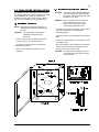
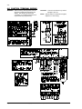
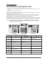
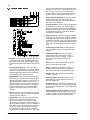
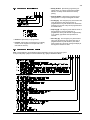
4/98 Reference Guide for the DS7060 Control/Communicator Keypad Quick Reference Guide Turning On (arming) your System Normal Arming Perimeter Arming, no entry delay Perimeter Arming, with entry delay Maximum Security Arming Force Arming Zone Bypass Custom Arm Quick Arm PIN + [On] PIN + [No Entry] [Perimeter Only] PIN + [Perimeter Only] PIN + [No Entry] [On] PIN + Arming Sequence + [Bypass] PIN + [Bypass] followed by the Zone number PIN + [#] + [4] [#] + [On] Turning Off (disarming) your System PIN + [Off] Commands for other System Features Chime Mode Zone Test Read Alarm History Battery Test Communicator Test Fire Reset Fire Trouble Remote Program Dial Out Remote Program Answer Local Battery/Sounder Test Error Display Error Display Reset Clear Zone Bypass Guest Code Enable PIN + [#] [7] PIN + [#] [8] [1] PIN + [#] [8] [9] PIN + [System Reset] PIN + [#] [8] [2] PIN + [System Reset] PIN + [Off] to silence, PIN + [System Reset] to clear PIN + [#] [8] [3] PIN + [#] [8] [6] PIN + [#] [8] [5] PIN + [#] [8] [7] PIN + [System Reset] PIN + [Bypass] [*] to clear PIN + [#] [8] [4] NOTE: Examples are shown in Commercial Mode, but are valid for any mode. Detection Systems PTY Ltd. Unit 21, 45 Gilby Road Mount Waverley 3149, Australia 61 3 9558 8088 Fax: 61 3 9588 8089 Detection Systems PTY Ltd. Unit 2, The Riverside Centre 148 James Ruse Drive Parramatta, NSW 2150, Australia 61 2 891 4944 Fax: 61 2 891 5844 Detection Systems, Inc., 130 Perinton Parkway, Fairport, New York, USA 14450-9199 Copyright 1997-98 Detection Systems, Inc. (716) 223-4060 • (800) 289-0096 • Fax: (716) 223-9180 DS7060-AUS Reference Guide P/N 36624C 4/98 =RQHV 6<67(029(59,(: The DS7060 Control/Communicator is a fully integrated hard-wire security and residential fire alarm system. It can support up to 6 input zones and 15 individual users. Up to 4 keypads may be used to provide user interface with the system, as well as programming access for the installer. .H\SDGV (QFORVXUH +RXVLQJ The enclosure is manufactured from 22 Ga. (0.65 mm), cold-rolled steel, and measures 9.25" Wide, by 10.25" High, by 3" Deep (23.5 cm Wide, by 26 cm High, by 7.6 cm Deep). The door has a knockout for a standard DS lock (optional). The enclosure has a slot in the back and also has an optional tamper switch mounting bracket with a plunger switch. 7HPSHUDWXUH • Storage temp: +32° to +120°F (0° to +49°C) -20° to +150°F (-28° to +66°C) 3RZHU • Input Power: 16.5 VAC (U.S.) 16 VAC (Aust), 20 VA, 50 or 60 Hz • Auxiliary Regulated Power: 12-12.5 VDC, 0.8 A • Auxiliary Power Voltage Range: • Optional Standby battery (P334): • Control Panel Current Draw: • DS7443 Keypad Current Draw: 10 to 13.8 VDC • Fuse 1 and 2: • Total number of keypads: • Max. wire length total in system: • Wire type: 4 Keypads 1000 ft. (305 m) 22 AWG (0.8 mm) NOTE: Keypads may be up to 1000 ft. (305 m) from the panel when #22 (0.8 mm) wire is used and only one keypad is connected to a particular wire run. &RPPXQLFDWRU Will report to two phone numbers with full single, double, and backup reporting. Communicated in 3/1, 3/1E, 3/1 with Parity, 3/1E with Parity, 4/1, 4/2, High Speed 4/9, Pager, Contact ID, and Personal Dialing formats. Refer to Sections 6.14 - 6.33 for communicator operation. The ringer equivalence is 0.1 B. 12 V, 7.0 AH 65 mA 45 mA, Standby 45 mA, Alarm • DS7445 Keypad Current Draw: 75 mA, Standby • DS7447 Keypad Current Draw: • Zone Response Time: All six zones can be programmed to respond at either 300 ±100 ms or a programmable time (common to all zones) that can be configured to be between 10 ms and 2.5 seconds. Zones are ignored for 15 seconds after power up, and for two seconds after a system reset. Refer to Sections 6.2 - 6.7 for detailed zone operation. 63(&,),&$7,216 • Operating temp: • 6 zones (9 if Zone Doubling is used) 75 mA, Alarm 100 mA, Standby 100mA, Alarm 1 A, 250 V 2XWSXWV 8VHUV The system allows up to 15 individual users. Each user will have his own PIN number (the 4 digit code entered at the keypads). /LJKWQLQJ 3URWHFWLRQ MOVs and/or spark gaps provide protection from lightning surges and static discharges. %XUJODU)LUH =RQH ,QSXWV • Number of Circuits: • Programmable Output 1*: Solid state, switch to ground (500 mA max.). • Programmable Output 2*: Solid state, switch to ground (500 mA max.). • Programmable Output 3*: Form “C” relay contacts available. Typical: Normally Open contacts that switch to 12 V @ 800 mA. * = Current draw should be subtracted from either maximum auxiliary or maximum alarm current draw. 6 Circuits on board • End-of-Line Resistor: 2.21k ohms NOTE: 4 wire type smoke detectors only. /LQH 6HL]XUH 1RWLFH This control panel incorporates a line seizure feature which will disable internal telephone lines when the control panel is sending alarm or supervision reports to the central station. Refer to Section 6.8 for detailed Output operation. Page 2 Copyright 1997-98 Detection Systems, Inc. DS7060-AUS Reference Guide 4/98 (1&/2685(,167$//$7,21 ,QVWDOO WKH &RQWURO&RPPXQLFDWRU The DS7060 control/communicator and the enclosure are shipped together. The control, however, still needs to be installed into the enclosure. Hardware for mounting the enclosure to a wall, and the control to the enclosure is located in its own hardware pack. CAUTION: ,QVWDOO WKH (QFORVXUH NOTE: This panel is intended for mounting in a restricted access area and should be wall mounted. CAUTION: The control panel should only be installed by authorized service personnel. The control is static sensitive. Make sure you touch earth ground before handling the control. This will discharge any static electricity in your body. EXAMPLE: Run the ground wire to the enclosure before handling the control. Then, holding the ground wire (or using a ground strap), install the control. • Insert the two support posts into the control retainer holes as shown below in the Support Post Assembly diagram. • Slide the top of the control PCB into the two retainer tabs. • Use the enclosure as a template and mark the mounting holes on the mounting surface. • Once in the retainer tabs, the control will rest on the two support posts. • Pre-start the mounting screws for these holes. Mount the enclosure. • Secure the bottom of the enclosure by screwing the bottom two holes through the support posts and through to the control retainer holes. • Knock out the desired wire entrances on the enclosure. DS7060-AUS Reference Guide CAUTION: Once the control is installed, be sure to connect its ground wire to the top hinge of the enclosure. Copyright 1997-98 Detection Systems, Inc. Page 3 4/98 &21752/7(50,1$/:,5,1* WARNING: Before servicing this equipment, remove all power including the transformer and battery. Also remove the phone line connection. A complete functional test is required after any programming. Page 4 CAUTION: Incorrect connections may result in damage to the unit. NOTE: Shared cable is not allowed for keypad, telephone, or siren wiring. Copyright 1997-98 Detection Systems, Inc. DS7060-AUS Reference Guide 4/98 2SHUDWLQJ*XLGH 8QGHUVWDQGLQJ WKH '6 '6 DQG '6 .H\SDGV • The DS7443 is a 6 zone LED keypad; its LEDs represent the zones of the system. • The DS7445 is an 8 zone LED keypad; its LEDs represent the zones of the system (LEDs for zones 7 and 8 are not used). • The DS7447 is an alpha-numeric LCD keypad. All three keypads display information on various control panel functions. A built-in sounder is used to annunciate keystroke entries and as an interior warning device. Volume Control (DS7445 and DS7447 only): The keypad sounder volume can be adjusted using the [1] and [4] keys along with the [*] key. Hold the [*] key while pressing the [1] key to increase the volume or the [4] key to decrease the volume. The volume adjustment does not affect the volume during an alarm. Backlight Control (DS7447 only): The display backlight intensity can be adjusted using the [3] and [6] keys along with the [*] key. Hold the [*] while pressing the [3] key to increase brightness or the [6] key to decrease brightness. NOTE: After the backlight and volume are adjusted, you must arm then disarm the system once to store this information in the control panel. If power is disconnected before the panel is armed, the backlight and volume levels return to the default settings. DS7447 KEYPAD DS7443 KEYPAD DS7445 KEYPAD This chart will help you understand what each Light/LED represents. LIGHT OFF FLASHING ON Armed (red) The control panel is disarmed. An exit delay is in progress or an alarm has occurred. The control panel is armed and no alarms have occurred. Status (green) One or more zones are not ready to arm. One or more zones are bypassed. All zones are ready to arm. Power (green) The control panel has lost power. No AC for battery. Control panel problems. Refer to Error displays. Normal operation. There are no fire alarms. A fire zone is in alarm. A fire trouble condition exists. The perimeter is not armed. This light will not flash. The perimeter is armed. Supervisory* (yellow) This light will not be sued by the DS7060. Not used. Not used. Bell Silenced* (yellow) The bells do not need to be or have not been silenced. This light will not flash. The bells have been silenced. To clear, enter the Fire Reset command. There are no trouble conditions. This light will not flash. A trouble condition exists. There are no zone alarms. A zone (1-6) is in alarm. A zone (1-6) is not ready to arm or if a fire zone, a trouble condition exists. Fire (red) Perimeter* (yellow) Trouble* (yellow) Zone LEDs** (red) * = This light is present on the DS7445 only. Page 5 ** = This light is present on the DS7443 and DS7445. Copyright 1997-98 Detection Systems, Inc. DS7060-AUS Reference Guide 4/98 3URJUDPPLQJWKH'6 $GGUHVV =RQH 3URJUDPPLQJ A zone is an input to the DS7060 Control Communicator. There are 6 hard-wired zones on the main circuit board. Perimeter Delayed: These zones have entry or exit delays unless the panel is armed in the “No Entry” mode. In the “No Entry” mode, the exit delay is in effect immediately after entering the “No Entry” mode, but is disabled upon expiration of the exit delay. A delayed zone is ignored during the programmed times immediately following arming during the exit delay. If the zone is faulted while the control is armed and not in exit delay then an entry delay cycle will be started, and a continuous entry tone will be sounded at the keypads. If the control is not disarmed by the end of the entry delay, an alarm will result. There are no keypad tones during the exit delay unless the feature “Keypad Audible During Exit Delay” is selected. Refer to Section 6.9, Address 09. If an entry delay is running and another entry delay zone is faulted, the entry delay timer is unaffected and will continue timing from the first entry. The entry delay time and exit delay time can be set independently. If a delayed zone remains faulted at the end of an exit delay, the panel will optionally signal an exit error condition. The entry delay will be begin as above, and the alarm output will activate with the pattern selected for that zone. If the control is not disarmed by the end of the entry delay, an alarm will result, and an exit error report will be sent to the central station (following the alarm report if programmed). The alarm output will deactivate. If the control is disarmed during the delay period started by the exit error condition, no reports will be sent to the central station and any outputs on during the exit error will deactivate. The exit error report does not follow the dialer delay option. • Disabled: These zones are not monitored, and will not generate alarm or trouble conditions. • Perimeter Instant: These zones arm and disarm with the panel, and never have entry or exit delays. Violation of this type of zone will cause an intrusion alarm. • 24-Hour Auxiliary: This zone type will cause an auxiliary alarm. It is always active. An alarm on a 24-hour zone (fire or aux.) will be silenced by entering a disarm code whether the control is armed or not. If the 24-hour zone restores and alarms again the alarm will sound again. 24-hour zones may generate trouble conditions during armed or disarmed periods. All 24-hour zones that have alarmed and are not restored will show as “Not Ready.” They will prevent arming unless the panel is force armed. 24-hour zones that have been bypassed manually will remain so until manually unbypassed, even if the control is armed and disarmed. Bypasses of these zones will be displayed on the keypad. • Interior Follower: This zone is not active when the panel is disarmed, or is armed in the perimeter only mode. When the zone is active, if a delayed zone is violated first, this zone is also delayed. If an instant zone or this zone type is violated first, this zone is not delayed. This zone is not active during the exit delay. • Interior Home/Away: This zone becomes interior instant if the system is armed and an entry/exit delay zone is violated during the exit delay time. If the system is armed and an entry/exit zone is not violated, these zones will be bypassed. These zones are bypassed if armed perimeter only. • Interior Instant: These zones arm and disarm with the panel. They are not active if the panel is armed in the “perimeter only” mode. They never have entry or exit delays. Violation of this type of zone will cause an intrusion alarm. • Perimeter Homeguard: This zone type is active when the panel is armed. When the panel is armed perimeter only, this is a delayed zone. When armed full, this is an instant zone. • Perimeter Follower Homeguard: These zones are always delayed when the panel is armed in the perimeter only mode. When the panel is fully Page 6 Copyright 1997-98 Detection Systems, Inc. DS7060-AUS Reference Guide 4/98 armed, these zones are delayed if a delayed zone is violated first, or instant if this zone or an instant zone is violated first. • Silence Audible: A zone configured as Silence Audible will, when activated, cause the panel to shut off output PO3 and keypad sounders. When this zone restores, the sounders will reactivate (if the timeout has not expired). It is used to facilitate voice communication for listen-in modules. • Keyswitch Toggle: Each time this zone is closed, it will toggle the armed state of the panel. It has a 300 ms response time. No alarms or trouble conditions are generated by a zone of this type. Optionally, to support this feature, the panel will generate a single siren beep for arm actions and a double beep for disarm actions. Note 1: If “Auto Bypass” is enabled (Address 10), Keyswitch Toggle will force arm a “Not Ready” zone. Note 2: Zone 9 is pre-programmed as a Keyswitch Toggle zone. • Keyswitch On/Off: Not available when zone doubling is used. When this zone is closed, it will arm the panel. When it is shunted by an EOL (supervised), the panel will be disarmed. No alarms or trouble conditions will be generated by a zone of this type. Opening the zone will not affect the arming state of the control. When this option is selected, keypads can not be used to arm or disarm the system unless the keyswitch zone is manually bypassed, prior to arming the system, from the keypad. If the keyswitch zone is bypassed, any keypad can perform all arming and disarming functions. Note: If “Auto Bypass” is enabled (Address 10), Keyswitch On/Off will force arm a “Not Ready” zone. • 24-Hour Fire with Verification: If a fire zone alarms and it is programmed for verification, the control will interrupt the programmable output(s) set as a switched power return for 10 seconds. During the 10 second power interruption, and for 15 seconds after power restoral, it will ignore all zone status on all fire zones (to ignore inrush currents). After fifteen seconds, it will monitor all fire zones for two minutes. If any fire zone returns to alarm within the two minute window it will create a fire alarm condition. If a fire zone does not go into alarm within the two minute window it will disregard the initial trip. If another alarm occurs on a fire zone with verification after the two minutes, it will start the process over. After any fire zone is in alarm, all subsequent fire zones are treated as instant (no verification) until the next fire reset. This same procedure will be performed when a [SYSTEM RESET] is entered, except that the two minute instant alarm monitoring period is not observed. be transmitted even though the panel may still be displaying these zone conditions. This is because the displays are latched until cleared by an operator action. NOTE: The use of the controls fire alarm verification feature may not be permitted in some areas. Check your local fire/building codes. • Fire: This zone is active and will alarm all 24 hours of the day regardless of the arming state of the control. An alarm on a fire zone will be silenced by entering a disarm code whether the control is armed or not. If the fire zone restores and alarms again the alarm will sound again. An open during the armed or disarmed period will send a trouble report and not an alarm. Fire zones are never silent, invisible, or swinger shunted. All fire zones that have alarmed will continue to show on all keypads until a fire reset is performed, even if they have physically restored. Fire zones may not be bypassed using the BYPASS command. NOTE: If force arming is enabled (see programming address 10), force arming is possible when the fire zone is violated (shorted). • Interior Delayed: This is a zone programmed to be ignored during the entry delay period. If it is violated when the system is armed, it will activate a delay for the programmed entry delay time. The keypad prealert sounders will activate and the alarm system may be disarmed during this delay period. If the system is not disarmed during this delay period, this zone will activate an alarm. • Day Monitor: This is a zone programmed to be a perimeter instant zone when the system is armed. When the system is disarmed, any violation of this zone will activate the keypad sounders which will sound continuously until a disarm sequence is entered. The alarm outputs for this zone will not activate and there will be no report sent for this zone when the system is disarmed. This zone will report a trouble condition if programmed. Since alarm and trouble reporting to the central station for fire zones is the same as for burg zones (i.e. it is based on the state of the zone) it is possible for Fire, and Fire Trouble restoral signals to DS7060-AUS Reference Guide Copyright 1997-98 Detection Systems, Inc. Page 7 4/98 $GGUHVV =RQH %\SDVV This determines whether the user can bypass the zone. Zones programmed for bypassing can be bypassed even when in alarm. Fire zones will not be bypassable, even if programmed as bypass allowed. • Alarm on Open: Works like Alarm on Short, but alarms when loop is opened. • Trouble on Short: This zone will alarm when the loop is shorted and the system is armed. It will generate a “Trouble” while unarmed and prevent arming unless the problem is cleared, Forced Armed, or Bypassed. • Trouble on Open: Works like Trouble on Short, but alarms when loop is opened. $GGUHVV 2XWSXW 7\SH $GGUHVV =RQH $FWLRQ • Invisible: This is a zone programmed not to have an alarm output or an alarm display at any keypad when activated. An alarm signal will be sent, but the keypad display will not indicate an alarm while this zone is violated. Invisible alarm zones are recommended for holdup alarms. • Silent: This is a zone programmed to activate the visual display at the keypad, but not audible signals. If this zone is also an entry zone, an entry tone will sound when this zone is activated. NOTE 1:Fire zones should always be programmed as alarm on short, trouble on open (selection 1). NOTE 2:If Zone Doubling is used, the Zone Action must be set for Trouble on Short, Alarm on Open. If Zone Doubling is not used, Alarm on Short with Trouble on Open will give a tamper condition on an open or short. • Alarm on Short: This zone will alarm when the loop is shorted and the system is armed. It will generate a “Not Ready” (or “Fire Trouble” on fire zones) while unarmed and prevent arming unless the problem is cleared, Forced Armed, or Bypassed. Page 8 • Steady: When this zone alarms all programmed outputs (prog1/prog2/prog3) will come on steady, unless they are already pulsing, in which case they will remain pulsing. • Pulsing: The pattern for the pulsing audible output will be 0.5 sec on, 0.5 sec off repeated three times, with an additional 1 second delay between repeats. When zones are tripped which could cause both pulsing and steady outputs, the pulsing output will prevail. The alarm outputs will continue to be activated until the bell cutoff timer times out or is reset and then they will silence. Only programmable output 3 and the keypad sounders will pulse, regardless of the programming. Copyright 1997-98 Detection Systems, Inc. DS7060-AUS Reference Guide 4/98 $GGUHVV =RQH 5HVSRQVH 7LPH $GGUHVV =RQH 5HVWRUDO 2SWLRQV All six zones can be programmed to respond at either 300 ms (±100 ms) or a programmable time (common to all zones, the time is programmed into Address 06) that can be configured to be between 160 ms and 2.5 seconds. • Restore when Sounders Silence: If programmed, a zone sends a restoral report and is ready to activate again only after the burglary bell cutoff time expires or the bells are silenced. The zone can alarm multiple times per armed period. $GGUHVV 3URJUDPPHG =RQH 5HVSRQVH 7LPH Sets the time value used in Address 05. • Restore with Zone: If programmed, a zone sends a restoral report and is ready to activate again as soon as it physically restores. The zone can alarm multiple times per armed period. • Restore when Disarmed (or Reset): If the zone returns to normal before the bell timer elapses, the alarm display will continue and no restoral will be reported. When the bell timer then elapses, whether or not the zone has restored, the bell will shut down (if selected) but the alarm display will continue and no restoral will be reported. When the system is disarmed (or reset) the bell will silence, the displays will clear and restoral will be reported along with the open/reset event (if programmed). If the zone is a 24 hour zone and has not restored to normal, will not report zone restoral until the zone restores. Unrestored 24 hour zones will show as “not ready” and will prevent the system from arming. In this case, the system will reinitiate the sounders and displays for those zones, but will not send any fire alarm transmission to the central station for those zones, unless a previous restoral has been sent. Fire zones always restore when the system is reset, regardless of this selection. DS7060-AUS Reference Guide Copyright 1997-98 Detection Systems, Inc. Page 9 4/98 $GGUHVV 2XWSXWV relay coil to the selected Programmable Output and the other side of the coil to 12 volts (Terminal 5) (if PO1 or PO2 is used), or to any Panel Common terminal if PO3 is used. Not intended for UL Listed systems. Not for use with phone line monitors. • Ready to Arm (System Status): This is an output programmed to follow the “Status” light of the keypad. It will activate when the system is ready to arm with no zones violated. • Follow Burg Alarm: This is an output programmed to activate when a zone is in an alarm condition. It will remain activated until the system is disarmed or the bell cutoff time expires. This output is intended to activate bells and sirens. This will not activate from Silent or Invisible zones. • Follow Fire Alarm: This is an output programmed to activate when a zone is in an fire alarm condition. It will remain activated until the system is disarmed (or silenced using PIN + [Off] ) or the bell cutoff time expires. This output is intended to activate bells and sirens. This will not activate from Silent or Invisible zones. • Follow Burg and Fire Alarm: This programs an output to activate when any zone goes into alarm condition. • Intrusion: This is an output programmed to latch with any Burg zone alarm, including invisible and silent zones. It will remain latched until the system is disarmed regardless of the restore setting for the zone. • On During Entry Pre-Alert: This is an output programmed to activate when a perimeter delayed type zone is violated while the system is armed. It will remain activated until the system is disarmed, or until the entry delay time has expired. • System Reset: This is an output programmed to activate only for 10 seconds after a PIN + [System Reset] is entered at a keypad or if a fire zone with verification activates. Output 1 turns on for 10 seconds, outputs 2 and 3 turn off for 10 seconds. Outputs 2 and 3 are intended to be used to power 4-wire smoke detectors or any other device that requires a power interruption to reset an alarm condition. • Armed: This is an output programmed to activate when the system is armed. It will remain activated until the system is disarmed. • Follow Keypad Sounder: This is an output programmed to follow the keypad sounder. It activates during the entry pre-alert . It does not follow momentary keypad beeps such as keystrokes. • Duress: This output activates when the duress code is used to disarm the system. Note: If the Duress code is used to activate a Programmable Output, entering any valid PIN + [OFF} will deactivate the Programmable Output. • Trouble: This output activates when a trouble condition is present. • Off During Battery Test: This output turns Off (deactivates) for 2 seconds during a manual or automatic battery test. • Partial Armed: This output activates whenever the system is armed with one or more zones bypassed. This includes manual bypasses, custom arming and force arming. • Follow Burg Alarm 20 Second Delay: This output will be delayed for 20 seconds after a zone enters an alarm condition. It will remain activated until the system is disarmed or the bell timeout expires. • Ground Start: This is an output programmed to activate for 3 seconds when the phone line is seized. It is intended for use with ground start phone systems that require a momentary short to ground to obtain a dial tone. Connect a separate 12 VDC, DPDT relay. Connect both relay commons to ground, and connect the N/O of each contact to terminal positions 23 and 26 (one to terminal 23, one to 26) of the DS7060. Connect one side of the Page 10 Copyright 1997-98 Detection Systems, Inc. DS7060-AUS Reference Guide 4/98 $GGUHVV 8VHU &RQWURO $GGUHVV *HQHUDO &RQWURO • Duress Code: If this option is selected and Code 14 is used to disarm the system, a duress report will be sent as the system is otherwise disarmed normally. User Code 14 will not arm the system, or report duress, if the system is not armed. • Guest Code: If this option is selected, Code 15 is a guest code. It can be enabled by pressing [PIN] [#] [8] [4]. It will remain active until the panel is disarmed with any other valid code. • Arming Warning: If this option is selected, the alarm output will turn on for 2 seconds when the panel is armed. • Keypad Audible During Exit Delay: Selection of this option will cause the keypad sounders to beep during the exit delay time. A one second beep will sound at 5 second intervals, changing to a 3-beep tone at 10 and 5 seconds prior to the end of the delay. • Keyswitch Arming Warning: Selecting this option will activate any output programmed as Intrusion, Follow Burg Alarm, or Follow Burg Alarm and Fire Alarm. The output will beep once (200 ms ON) when a keyswitch toggle zone arms the system. A double beep will occur (200 ms ON-OFF-ON) when a keyswitch toggle zone disarms the system. • Siren on Comm. Fail for Silent Zone: If programmed, a silent zone will sound the alarm outputs if the zone is in an alarm condition and the system fails to communicate with the central station. • Closing Ringback: If programmed, the keypad sounders and Output 3 will activate for 2 seconds after the system is armed and the closing report is successfully sent. This requires Closing Ringback and Closing Report to be programmed. If the panel does not report to a central station, use “Arming Warning” in Address 9. • Swinger Shunt: If enabled, a zone can only alarm or trouble up to three times per armed period. After the third alarm or trouble, the zone will be bypassed and a bypass report for this zone will be sent. Fire zones are never swinger shunted. • 50 Hz/60 Hz: Set to local power type. The panel clock is synchronized to the power line frequency. 60 Hz required for UL Listed Requirements. • Keypad Mode: Commercial Mode requires a PIN number for all functions. Residential Mode only requires a PIN number for disarming and silencing alarms. • Quick Arm: If enabled, a PIN is not needed to arm. Note: Used only in conjunction with commercial mode. DS7060-AUS Reference Guide Copyright 1997-98 Detection Systems, Inc. Page 11 4/98 • Easy Exit: If the system is armed and there have been no zones violated, then you can reenter a Quick Arm Command without first disarming the system. This allows you to change the arming level or to restart the exit delay so you can exit through an entry/exit zone. $GGUHVV WKUX $OSKD /DEHO • Force Arming Limit: If enabled, the system can be armed when zones are violated or if an AC power failure has occurred, by pressing the [Bypass Key] after an arming command. If bypassing is not allowed, a three beep error tone will sound and the panel will return to standby mode. • Address 14: Zone 2 Alpha Label: • Address 12: Private Label - The private label will display when the system is Ready to Arm and when it is Armed. • Address 13: Zone 1 Alpha Label: • Address 15: Zone 3 Alpha Label: • Address 16: Zone 4 Alpha Label: • Address 17: Zone 5 Alpha Label: • Address 18: Zone 6 Alpha Label: Note: If “Auto Bypass” (Address 10) is enabled, arming the panel will automatically bypass the corresponding number of zones programmed into Force Arming Limit. If “Auto Bypass” is disabled, any zones that were programmed to be bypasses in Address 02, may be Auto Bypassed. • Auto Bypass: If enabled, the system will automatically bypass faulted zones when an arming command is used. If bypassing is not allowed on the “Not Ready” zone, a three beep error tone will sound, and the panel will return to standby mode. Note: When enabling Auto Bypass, it may be desirable to program “Force Arming Limit” (Address 10). If “Force Arming Limit” is set to 0, Auto Bypass will allow bypassing of any zone that was programmed to be bypassed by Address 02. If “Force Arming limit” is programmed between 1 and 6, this is the maximum number of zones that can be Auto Bypassed. $GGUHVV .H\SDG $VVLJQPHQW The keypad type (LED or Alpha) or no keypad must be programmed. Example: To program “ABC Alarm” as the Private Label Enter the Programmer’s Mode: Enter the Program Address: Enter: Enter: Enter: Enter: Enter: Enter: Enter: Enter: Enter: Enter: Page 12 Copyright 1997-98 Detection Systems, Inc. [9] [8] [6] [#] [0] [1] [2] followed by [#] [2] for the letter “A” then press the right arrow key for the next letter. [2] twice for the letter “B” then press the right arrow key for the next letter. [2] three times for the letter “C” then press the right arrow key for the next letter. [1] until you have a blank space. Note: moving the cursor to the left does not create a space. Spaces must be programmed into the Alpha using the [1] key. [2] for the letter “A” then press the right arrow key for the next letter. [System Reset] This key is the upper/lower case toggle. [5] three times for the letter “l” then press the right arrow key for the next letter. [2] for the letter “A” then press the right arrow key for the next letter [7] twice for the letter “r” then press the right arrow key for the next letter. [6] for the letter “m”. [#] Program the next address, program a different address, or exit the Programmer’s Mode. DS7060-AUS Reference Guide 4/98 $GGUHVV 6SHFLDO .H\V • Steady Audible: Special Key programming for steady alarms on outputs and keypad sounders. Will turn on steady unless alarms are already pulsing. • Pulsing Audible: Special Key programming for pulsing alarms on output and keypad sounders. • Fire Key [A]: The emergency key at the bottom left of the keypad entry area is the Fire Key. If programmed, the key will activate a fire alarm when pressed for 2 seconds. May not be programmed as an invisible alarm. • Help Key [B]: The help key at the bottom center of the keypad entry area is the Help Key. If programmed, the key will activate a supplementary or an auxiliary type alarm when pressed for 2 seconds. • Disabled: Special Key not programmed. • Invisible: Special Key programming for no display of alarm on the keypad or on outputs. Not to be used with the Fire Key. • Panic Key [C]: The emergency key at the bottom right of the keypad entry area is the Panic Key. If programmed, the key will activate a panic alarm when pressed for 2 seconds; nothing will display at the keypad to indicate an alarm. $GGUHVV 5HSRUW &RQWURO Note: Closing Reports ( and subsequent Opening Reports) are only sent when the system is fully armed. [PIN] + [ON] for Commercial Mode. [#] + [ON] for Residential Mode. DS7060-AUS Reference Guide Copyright 1997-98 Detection Systems, Inc. Page 13 4/98 $GGUHVV 3KRQH 1XPEHU &RQWURO • Answering Machine Bypass: This feature allows the control panel to answer incoming calls when answering machines are used. If the line rings, stops ringing, then rings again within one minute, the panel will seize the phone line on the first ring. To disable this feature, program the control panel to answer on an even number of rings. • Dialer Delay: A Dialer Delay of 15 seconds can be added when reporting burglar alarms, 24-hour burglar alarms, and fire alarms. This delay will help to prevent false alarm reports by giving the user 15 seconds to disarm the system before a report is sent. $GGUHVV 'LDO $WWHPSWV • Dial Pulse: If programmed, the panel will dial to phone number 1, 2, or 3 using a pulse format. • Dial Tone: If programmed, the panel will dial to phone number 1, 2, or 3 using a tone format. Note: When dialing through PBX systems, program the phone control as tone dial only. $GGUHVV 7LPH 'HOD\V • Tone with Auto Switch to Pulse: If programmed, the control panel will try to dial the first digit in tone dial and check to see if the dial tone has been broken. If it has not been broken, it will try to dial again using pulse dial. Note: Do not use this setting for PBX systems. • Tone with No Switch to Pulse (required for PBX): This setting will only use Tone dialing. Must be used if the telephone system requires you to dial a number to get an outside line. • Callback for Downloading: When enabled, if an attempt is made to connect to the panel for a remote programming session the panel will hang up and callback the number programmed for Phone 3, Address 44 and 45. • Ring Count: The control panel can be programmed to answer the phone after a selected number of rings for remote programming access. • WDSRP Baud Rate: This selection determines the baud rate that the panel will use to Page 14 Copyright 1997-98 Detection Systems, Inc. DS7060-AUS Reference Guide 4/98 5HSRUWV Program locations 24 through 36 are used differently for the particular Phone Format Chosen (see Address 38, 39). If Zone Doubling is selected in Address 55, Fire and Tamper reports are programmed in Addresses 56 and 57 for Zones 7 and 8. • Keypad Fire Report: This report is sent when a fire alarm has been activated using the “A” emergency key. • Keypad Fire Restoral Report: This report is sent when a keypad fire alarm has been restored using the [System Reset] command. • If a value of 00 is programmed in any of these locations the panel will not send that particular report. • Keypad Help Alarm Report: This report is sent when an help alarm has been activated using the “B” emergency key. • Pulsed Formats (3/1, 3/1E, 3/1 with Parity, 3/1E with Parity, 4/1, and 4/2) will need a unique value placed at each address location. Please note that each Central Station receiver differs slightly in the report codes that it expects. Therefore, it is best to verify the codes you use with the Central Station. Some of the reports that can be sent, such as OPEN, CLOSE, PARTIAL CLOSE can send an associated User Number as the second digit. To accomplish this, program an F (*5) as the second digit in the program location. When the report is sent the panel will replace the F with the appropriate user number. Pulsed formats 3/1, 3/1 with Parity, and 4/1 need a 0 for the second digit and cannot send user numbers. A non-zero in the second digit location indicates an extended 3/1E or 4/1E format. • Keypad Panic Report: This report is sent when an emergency alarm has been activated using the “C” emergency key. $GGUHVV =RQH $ODUP 5HSRUW • Fixed Report Formats (Contact ID, SIA, 4/9) have well defined reports that are sent regardless of the value programmed in the report code location. Any non-zero value programmed in the report code location will send the appropriate report. • Special Formats (Personal Dialing Format, Pager) are not recommended for primary reporting. If they are used, Personal Dialing Format could use the same report codes as the Pulsed Formats. Pager has a limitation in that it can’t use the Hex values A (*0), B (*1), C (*2), D (*3), E (*4), F (*5). These values can not be passed on to a Numeric Pager. $GGUHVV .H\SDG 5HSRUW • Zone Alarm: An alarm report is sent when a zone alarm occurs. Program this report for any zones where an alarm report is desired. For local zones (no reports), replace the default value with 00. $GGUHVV =RQH $ODUP 5HVWRUDO 5HSRUW • Zone Alarm Restoral: This report is sent when the zone alarm is cleared. Refer to Address 07 for exact point at which report will be sent. DS7060-AUS Reference Guide Copyright 1997-98 Detection Systems, Inc. Page 15 4/98 $GGUHVV =RQH 7URXEOH 5HSRUW $GGUHVV =RQH %\SDVV 5HSRUW • Zone Trouble: This report is sent when a zone trouble condition occurs. • Zone Bypass Reports are sent with the Closing Report. Address 20 digit 1 (left most digit) must be set for 2 or 3 for these reports $GGUHVV =RQH 7URXEOH 5HVWRUDO 5HSRUW $GGUHVV =RQH %\SDVV 5HVWRUDO 5HSRUW • Zone Trouble Restoral: This report is sent when the zone trouble condition is cleared. • Zone Bypass Restoral Reports are only sent with an Opening Report. Address 20 digit 1 (left most digit) must be set for 2 or 3 for these reports. Page 16 Copyright 1997-98 Detection Systems, Inc. DS7060-AUS Reference Guide 4/98 $GGUHVV 2SHQ&ORVH 'XUHVV 5HSRUW $GGUHVV %DWWHU\ $& 5HSRUW • Low Battery Report: This report is sent when a low battery condition occurs. • Low Battery Restoral Report: This report is sent when a low battery condition restores. • Open: This report is sent when the system has been disarmed. In Contact ID, SIA or 4/9 formats, the user number for the person who disarmed the system will be sent with this report. To send the user number along with an Open Report in other formats, program the extended digit of the report as F ([*] [5]). The Open Report will only be sent if a Close Report was sent previously. • Close: This report is sent when the system has been armed. In Contact ID, SIA or 4/9 formats, the user number for the person who armed the system will be sent with this report. To send the user number along with a Close Report in other formats, program the extended digit of the report as F ([*] [5]). • AC Failure Report: This report is sent after an AC failure condition occurs. AC failure reports will only be sent along with other reports if Address 50 is set to “000.” Otherwise reports will be sent after the delay set in Address 50. • AC Failure Restoral Report: This report is only sent along with other reports if Address 50 is set to “000.” Otherwise reports will be sent after the delay set in Address 50. $GGUHVV 3URJUDPPLQJ 5HSRUW • Duress: This report is sent when the system is disarmed using a duress code. The user number will not be sent along with this report. • Partial Close: This report is sent when the system is armed partially, or force armed. • First Open After Alarm: This report is sent when the system is disarmed after an alarm has occurred. It will also be sent if the system is already disarmed and a user number is entered to silence a 24-hour or fire zone. • Remote Programming Successful: This report is sent after a Remote Programming session, if the session was terminated properly. • Remote Programming Unsuccessful: This report is sent after a Remote Programming session, if an error occurs or session doesn’t terminate properly. • Local Programming Successful: This report is sent when local programmer’s mode is exited and no error is associated with the programming. DS7060-AUS Reference Guide Copyright 1997-98 Detection Systems, Inc. Page 17 4/98 $GGUHVV 6\VWHP 5HSRUW • Comm. Failure Report: This report is sent after the programmed number of communicator attempts. Refer to Address 22 - Dial Attempts. • Comm. Restore Report: This report is sent after there has been a communicator failure. Retries will occur after 30 minutes, then every 24 hours or when a new event occurs. When the next successful communicator attempt occurs, this report will be included. $GGUHVV 7HVW 5HSRUWV 6\VWHP 7HVW • System Trouble: This report is sent when a control trouble condition occurs. • System Trouble Restoral: This report is sent when all system trouble conditions restore. $GGUHVV ([LW (UURU 5HFHQW &ORVLQJ &RPP )DLOXUH 5HSRUW • Automatic Test Report: This report is sent at fixed intervals determined by programming Address 48 - Automatic Test Report Interval. By default, the panel will send the first automatic report 12 hours after the panel has been powered up, and from that point on, it will follow the interval selected by Address 48. The time before the first Automatic test report is sent can be adjusted between 1 and 24 hours after the panel has been powered up by setting Address 49 - Hours to First Auto Test Report. • Communicator Test Report: This report is sent as a result of initiating a Communicator Test, a PIN + [#] [8] [2] command sequence. Requires that Addresses 37 “Account Code”, 38 “Phone # 1 Format” and 40 “Phone #1 be programmed. • System Test: This report is sent when a system test has been started using the [#] [8] [1] key sequence. • Exit Error: This report is sent if an exit error occurs. An exit error occurs when an entry/exit zone is still violated at the end of the exit delay. If this happens, the entry delay will begin. If the system is not disarmed before the entry delay expires, an alarm report for the effected zone will be sent and the Exit Error Report will be sent. • System Test Restoral: This report is sent when the system test [#] [8] [1] has been completed or has timed-out. • Recent Closing: This report is sent, along with any alarm reports, when there is an alarm within the first five minutes after the system has been armed. Page 18 Copyright 1997-98 Detection Systems, Inc. DS7060-AUS Reference Guide 4/98 $GGUHVV $FFRXQW &RGHV NOTE: If the account code is “0000” no reports will be sent. NOTE: If a 3-digit code is required (when using pulse formats 3/1 and 3/1 with Parity) the fourth digit must be 0. For example: If the account code is 121, program 1210 in the account code address. NOTE: If using personal dialing or Pager format an account code is still required, even if the system does not report to a central station. The account code must use digits 0-9. A-F cannot be displayed on a pager. $GGUHVV 3KRQH )RUPDW $GGUHVV 3KRQH )RUPDW $GGUHVV 3KRQH 5HSRUWLQJ $GGUHVV 3KRQH 5HSRUWLQJ $GGUHVV 3KRQH 5HPRWH 3URJUDPPLQJ Address 40 Phone #1 (digits 1-16) Address 41 Phone #1 (digits 17-32) Address 42 Phone #2 (digits 1-16) Address 43 Phone #2 (digits 17-32) Address 44 Phone #3 (digits 1-16) Address 45 Phone #3 (digits 17-32) Note: DS7060-AUS Reference Guide To dial the [*] character, enter *1 (the [*] character is sent as “1” “1” when pulse dialing). The letter “B” will be displayed. To dial the [#] character, enter *2 (the [#] character is only valid when tone dialing). The letter “C” will be displayed. To input a three second delay, enter *3. The letter “D” will be displayed. To wait for the dial tone, enter *4 in the first digit. The letter “E” will be displayed. To disable a phone number, enter *5 in the first digit. The underscore “_” will de displayed. To delete the phone number from the display window, enter the *5 in all digits. Copyright 1997-98 Detection Systems, Inc. Page 19 4/98 $GGUHVV 3URJUDPPHU 0DVWHU &RGHV See the Users Guide for more information on Personal Identification Numbers. $GGUHVV +RXUV WR )LUVW $XWR 7HVW 5HSRUW • Set this value to the number of hours from the time the panel was powered up for the first report. Example: If the panel was powered up at 2 PM and you want test reports at 3 AM, set to [0 1 3] (2 PM + 13 hours = 3 AM). If not set, the first report will be sent 12 hours after panel power up. $GGUHVV $& )DLOXUH 5HSRUW 'HOD\ $GGUHVV 'HIDXOW ((3520 • Address 32 must be programmed to this report. CAUTION: Entering a [1] in Address 47 will erase all prior programming. Note: If AC power should restore before the “AC Failure Report” time, no AC Failure Report will be sent. $GGUHVV $XWRPDWLF 7HVW 5HSRUW ,QWHUYDO Page 20 Copyright 1997-98 Detection Systems, Inc. DS7060-AUS Reference Guide 4/98 $GGUHVV +LVWRU\ &RQWUROV $GGUHVV =RQH 'RXEOLQJ History Controls determine what events are stored in the panels history buffer. Zone Doubling adds three additional specific zones to the control panel: Zone 7 - Fire: Supervised for use with 4-wire smoke detectors. Zone 8 - Tamper: Supervised for use with tamper switches. Zone 9 - Keyswitch: Supervised keyswitch input. A momentary contact closure on this input will toggle the panel between the armed and disarmed states. NOTE: The zone input wiring and End-OfLine resistors differ if Zone Doubling is selected. Be sure to review Section 4.0, Terminal Wiring, for the correct resistor selections. $GGUHVV ([SDQGHG =RQH 5HSRUWV $GGUHVV &XVWRP $UPLQJ Custom Arming programming allows the [#] + [4] key sequence on the keypad to be used for custom arming. The programming determines which zones will be bypassed (not armed) during custom arming. Note: Custom Arming will send a Partial Closed report if programmed to do so in Address 31. Expanded Zone Reports are used only if Zone Doubling (see Address 55) is selected. $GGUHVV ([SDQGHG =RQH 5HVWRUDOV Expanded Zone Restorals are used only if Zone Doubling (see Address 55) is selected. DS7060-AUS Reference Guide Copyright 1997-98 Detection Systems, Inc. Page 21 4/98 $GGUHVV &XVWRP &KLPH Custom Chime determines which zones will chime in the chime mode. Only Zones programmed as Perimeter Instant, Perimeter Delayed, Perimeter Homeguard or Perimeter Homeguard Follower in Address 01 can be chime zones. Page 22 Copyright 1997-98 Detection Systems, Inc. DS7060-AUS Reference Guide Example PIN NUMBER NAME 1038 Thomas J. Brown User 01 User 02 User 03 User 04 User 05 User 06 User 07 User 08 User 09 User 10 User 11 User 12 User 13 User 14 User 15 Example DEVICE LOCATION TYPE PIR Kitchen Invisible alarm, alarm on short, alarm on open, 24-hour Zone 1 Zone 1 Zone 1 Zone 1 Zone 1 Zone 1 Page 23 Copyright 1997-98 Detection Systems, Inc. DS7060-AUS Reference Guide Detection Systems (Aust) Pty Ltd DS7060 Reference Guide P/N 36624B