1
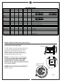
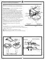
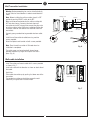
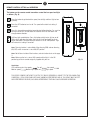
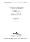
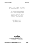
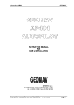
CEILING FAN REMOTE CONTROLLER
INSTALLATION AND OPERATION INSTRUCTION
CONTENTS
Safety information ......................................................................................................................... 1
General guide ................................................................................................................................ 2
Function chart................................................................................................................................ 3
Remote control setting (Dimming/Non Dimming) .......................................................................... 3
Installation and wiring .................................................................................................................... 4
Remote control setting and operation ........................................................................................... 7
Trouble shooting and warranty...................................................................................................... 9
SAFETY INFORMATION
READ AND SAVE THESE INSTRUCTIONS
• Please read and understand this entire manual before attempting to assemble, install or operate
the product.
• Make sure that all electrical connections comply with local codes, ordinances, the National
Electrical Code and ANSI/NFPA 70-1999. Hire a qualified electrician or consult a do-it-yourself
wiring handbook if you are unfamiliar with installing electrical wiring.
• Before proceeding, be sure to shut off electricity at main switch or circuit breaker in order to avoid
electrical shock.
MCRC1, MCRC1R, MCRC2R, MCRC3,
MCRC3R, MCRC4R series
General Guide
This remote controller operates with 3V CR2032 battery (battery included).
Store the remote controller away from excess heat or humidity
Make sure the fan is set on HIGH speed and the light is in the ON position by pull chain
controls originally supplied with your fan.
For downrod mount fans- Remove Ceiling fan CANOPY from its mounting bracket and
disconnect existing wiring for Remote control receiver installation and wiring. Replace it
after installation.
For Flush mount fans- Remove Ceiling fan housing or mounting bracket from mounting
plate and disconnect existing wiring for Remote controller receiver installation and wiring.
Replace it after installation.
Warning: Before proceeding, be sure to shut off electricity at main switch or circuit breaker in
order to avoid electrical shock.
Note: Fan installation must be complete including assembly of blades before testing remote
control unit.
Note: Refer to your Ceiling fan instruction manual for Safety and installation instruction.
This remote controller is to be used for the control of ceiling fan only, and in an AC 120V
60HZ power supply only.
The power supply to the remote control receiver should be connected through a switch, i.e.
existing wall switch.
Do not use the remote controller with SOLID-STATE fans.
Do not use the remote controller with outdoor fans.
Customer Service
800-969-3347
Customer Service Center
7400 Linder Ave.
Skokie, IL 60077
www.montecarlofans.com
© 2013 Monte Carlo Fan Company
2
9/25/2013
Item number VS Function
Model\Function
Fan Speed Fan off
Reverse
MCRC1 series
v
v
MCRC1R series
v
v
v
v
MCRC2R series
v
v
MCRC3
v
v
MCRC3R series
v
v
MCRC4R series
v
v
MCRC1T series
v
v
MCRC1RT series
v
v
MCRC2RT series
v
v
MCRC3W
v
v
MCRC3RW
v
v
MCRC4RW
v
v
Light
Up light
SKU #
v
MCRC1, MCRC1AL
v
MCRC1RRZW/RB/BS/PN/BP, MCRC1RALRZW/RB/BS/PN/BP
v
v
MCRC2RRZW/RB/BS/PN/BP, MCRC2RALRZW/RB/BS/PN/BP
v
MCRC3
v
v
MCRC3RRZW/RB/BS/PN/BP
v
v
v
MCRC4RRZW/RB/BS/PN/BP
v
MCRC1T, MCRC1TAL
v
v
MCRC1RT, MCRC1RTAL
v
v
v
MCRC2RT, MCRT2RTAL
v
MCRC3W
v
v
MCRC3RW
v
v
v
MCRC4RW
MCRC-RC1
v
v
v
MCRC-RC1
MCRC-RC1R
v
v
v
v
MCRC-RC1R
MCRC-RC2R
v
v
v
v
v
MCRC-RC2R
REMOTE CONTROL SETTING (Dimming/Non Dimming)
Dimming Non Dimming Setting
Canopy type receiver
The “DIM” selection is the light dimmable selection and it
is to be used with incandescent light bulbs including
halogen bulbs and dimmable LED luminaries. The
“ON/OFF” selection is the light ON/OFF only (non
dimming function) and it is to be used with CFL bulbs
and other non dimmable luminaries. (Fig. 1 )
DIM
ON/OFF
Warning: The remote controller is set with dimming
function at factory, make sure to select “ON/OFF”
(non dimming function) when use this remote
controller with CFL and other non dimmable
luminaries. Wrong setting may damage the light kit
or the remote controller.
Switch housing type
receiver
Caution: If the remote receiver has been wired with fan,
turn power off by wall switch before switch “DIM” and
“ON/OFF” selection.
Fig. 1
© 2013 Monte Carlo Fan Company
3
9/25/2013
Installation and Wiring (Canopy Mount)
Warning: Before proceeding, be sure to shut off electricity at
main switch or circuit breaker in order to avoid electrical shock.
Make wire connections as shown in wiring diagram using wire
connectors provided.
Connect WHITE wire from motor assembly to
WHITE wire from remote control receiver marked TO MOTOR N,
BLUE wire from motor assembly to BLUE wire from remote
control receiver marked FOR LIGHT. Connect BLACK wire from
motor assembly to RED (or BLACK) wire from remote control
receiver marked TO MOTOR L. Connect BLACK (Live) wire from
house to BLACK wire from remote control receiver marked AC IN
L. Connect WHITE (Neutral) wire from house to WHITE wire from
remote control receiver marked AC IN N. Connect GROUND LEAD
(Green ) from fan to GROUND LEAD from house. (Fig. 2)
BLACK/LIVE
(AC IN L)
WALL SWITCH
AC POWER
SUPPLY
WHITE/NEUTRAL
(AC IN N)
ANTENNA
BLACK
BLUE
(FOR LIGHT)
WHITE
(TO MOTOR N)
RED (or BLACK)
(TO MOTOR L)
Note: If the fan includes up light, connect ORANGE wire from fan
to ORANGE wire from remote control receiver marked FOR UP
LIGHT if the remote controller includes up light function.
Note: Make sure there is no bare wire is visible at wire
connectors.
GROUND LEAD WIRE
FROM FAN
GROUND LEAD WIRE
FROM HOUSE
For downrod mount fans, lay the receiver in the canopy as shown
in Fig. 3. For flush mount fans, attach the receiver to mounting plate with wrap
supplied as shown in Fig. 3-1.
Fig. 2
Note: Mounting mean of fan may be different than shown.
Note: Electrical rating for fan motor is 1 A max and 300W max for light.
CEILING
JUNCTION BOX
RECEIVER
MOUNTING PLATE
Fig. 3
© 2013 Monte Carlo Fan Company
Fig. 3-1
4
9/25/2013
Installation and Wiring (Switch Housing Mount)
Warning: Before proceeding, be sure to shut off electricity at main switch or circuit breaker in order to avoid electrical
shock.
Remove switch housing from fan by unscrewing the 4 side mount screws. Keep the screws.
Disconnect plugs in switch housing by pushing down on tab and pulling the plugs apart. (Fig. 4)
Align the central hole of remote receiver with the hole (with plug) in the New switch housing and attach the remote
receiver onto switch housing by preadhered double-sided foam tap as shown. (Fig.4-1)
Connect the plug from fan to the plug from receiver (receiver with switch housing), aligning the clasp and make sure
plugs connected securely. (Fig. 4-2)
Install the switch housing onto the fan with the 4 side mount screws which were just removed. (Fig.4-2)
Helpful hint: Keep wires and plugs away from the capacitor may make it easier for switch housing installation.
If install light kit with the fan, Remove switch housing from fan if it is preassembled on the fan.
Remove tap from New switch housing. Remove hex nut and lock washer from light fixture and then Install the New switch
housing onto light fixture by turning clockwise till tight. Place the lock washer and hex nut over lead wires and tighten the
hex nut on the thread rod of light fixture. (Fig.4, Fig.5)
Place receiver over lead wires and thread pipe from light fixture and stick receiver on switch housing by preadhered
double-sided foam tap as shown. Connect WHITE wire from remote receiver to WHITE wire from light fixture. Connect
BLUE wire from Remote receiver to BLACK (or BLUE) wire from light fixture. Be sure plugs connections snap together
completely. (Fig. 5)
Note: Make sure the light kit is set at ON position by pull chain switch originally supplied with your light kit.
Note: Electrical rating for fan motor is 1.5 A max and 300 W max for light.
Receiver
Double-sided foam tap
Tap
Receiver
Capacitor
Set screws
Switch housing
Tap
Capacitor
Receiver
Set screws
Fig. 4
Hex nut
Lock washer
Fig. 4-1
Switch housing
Fig. 4-2
Lead wires
Switch housing
Light fixture
Fig. 5
© 2013 Monte Carlo Fan Company
5
9/25/2013
Wall Transmitter Installation
Warning: Before proceeding, be sure to shut off electricity
at main switch or circuit breaker in order to avoid electrical
shock.
Switch cover
Note: Before installing the wall transmitter, place it in OFF
position by pushing ON/OFF switch to the OFF.
Ground
To load
Make series-wound connection for the wall transmitter with
HOT wire from house. Connect a black wire from wall
transmitter to the HOT wire and then connect the other wire
of wall transmitter to the LOAD wire in outlet box (Follow the
instruction shown on the labels on the lead wires from wall
transmitter).
Wall
Box
Wall plate
Connect green grounded wire to grounded wire from outlet
box.
OFF
Install the wall transmitter to outlet box using machine
screws provided.
Wall transmitter
Hot to
AC source
ON
Attach wall plate to wall control unit with screws provided.
Note: Place the wall transmitter in ON mode when fan
installation is completed.
Fig. 6
The switch cover can be replaced with almond cover
provided. Remove it by finger and snap the new one in
place. (Fig. 6)
Wall cradle installation
Install Transmitter wall mount cradle with 2 screws provided
as shown in Fig. 7.
Install wall cradle with the direction as shown on back side of
the cradle.
Useful tips:
Take remote transmitter up by pushing it at lower area of the
transmitter.
The remote transmitter can be held on magnetic metal
material by a magnet built in the transmitter.
Back side of the
wall mount cradle
Fig. 7
© 2013 Monte Carlo Fan Company
6
9/25/2013
REMOTE CONTROL SETTING and OPERATION
Transmitter Operation
1. Remove the battery seat from the bottom of remote control
transmitter and install battery. Replace the battery seat. (Fig. 8)
Back side of
transmitter
Note: Use a 3V CR2032 battery. The battery will weaken with age and should
be replaced before leaking as this will damage the transmitter. Dispose of
used battery properly, keep the battery out of reach for children.
Useful tips
Remove battery seat by pushing at “A” position as shown in Fig. 8 toward to
right hand side and pull it out. Install CR2032 battery into battery seat (make
sure the side with “+” is upward) and reinstall the battery seat.
Fig. 8
A
2. Learn function setting, Restore power source to your fan, press and
hold the “OFF” button for at least 4 seconds. You must press the ‘OFF” button
within 60 seconds of restoring power to the fan. (Fig. 8-1)
“OFF”
Note: If the fan is installed with light (down light), light will twinkle twice then
off. The remote control setting process is complete and your fan is ready for
use. For fans without light, check operation using remote transmitter.
Note: If you want to control the fan with another transmitter, make the same
setting. A fan can be controlled by 2 transmitters maximum.
Note: If the power is on already, you must turn the power off, and then turn
the power back for remote control learn function setting.
Note: If you press wrong buttons, you must again turn power off and turn the
power back then reset learn function.
Fig. 8-1
Tips for end users
1. If your fan is operated automatically after installation and power on, it is because your fan is still memorize the previous
setting at factory. Make learn function setting and your fan will be ready for use.
2. If fan or light isn’t working, reset power (turn the power off for at least 5 seconds and then turn the power back) and redo the
learn function setting.
3. It is not available to separately operate the remote setting for more than one fan in the same room (in the area where remote
signal can reach to) if they share the same power supply. Separate power supplies (like as using individual wall switches for each
fan) is required if you want to separately control more than one fan in same room.
4. There might be other remote transmitters got the same code combination as the transmitter that you are using, you may
remove the code setting of the other transmitters by turn the power off and turn it back and then push and hold the “OFF” button
of the transmitter which you are using for at least 10 seconds. You must press the ‘OFF” button within 60 seconds of restoring
power to the fan.
© 2013 Monte Carlo Fan Company
7
9/25/2013
REMOTE CONTROL SETTING and OPERATION
The buttons on the remote control transmitter control the fan speed and light
as follows. (Fig. 9)
Press the button to get desired fan speed, Low to High and then High to Low
cyclically.
Press the OFF button to turn fan off. Fan speed will maintain last setting if
turned off.
Press this forward/reverse button to get desired airflow direction. Fan must be
running to reverse. It will take about 25 seconds for fan to slow down and
change rotation direction.
Up/Down light control button. Press this button quickly to turn light on or off.
To dim light, hold down the button, the light will cycle from bright to dim to
bright until button is released when the receiver is set at “DIM” position. Light
will maintain last setting if turned off.
Note: Dimming function is not available if the dimming (DIM) and non dimming
(ON/OFF) switch in receiver is set at ON/OFF position.
Note: Not all items include all the functions, refer to function chart on the page
3.
Note: Make sure the fan is set on HIGH speed and the light is in the ON
position by pull chain controls originally supplied with your fan.
Fig. 9
Useful tips
LED indicator against fan speeds,
Fan off,
Medium speed,
Medium high speed and
Low speed,
High speed.
THIS DEVICE COMPLIES WITH PART 15 OF THE FCC RULES OPERATION IS SUBJECT TO THE FOLLOWING TWO
CONDITIONS. (1)THIS DEVICE MAY NOT CAUSE HARMFUL INTERFERENCE AND (2) THIS DEVICE MUST ACCEPT
ANY INTERFERENCE RECEIVED, INCLUDING INTERFERENCE THAT MAY CAUSE UNDESIRED OPERATION.
© 2013 Monte Carlo Fan Company
8
9/25/2013
Trouble Shooting
Warning: Before beginning work, shut off the power supply to avoid electrical shock.
PROBLEM
POSSIBLE CAUSE
CORRECTIVE ACTION
Fails to operate
1. Power is off.
1. Check main and branch fuses
or circuit breakers.
2. Turn power off and turn it back,
reset learn function with in 60
seconds after turn power back.
2. Learn function is not setting well.
3. Turn power off and check all
wire connections.
4. Replace battery.
3. Faulty wire connection.
4. Out of battery (Transmitter).
Short remote range
5. The fan is not set at high speed and
the light is not set at ON position.
5. Check it and correct it.
1. Battery is low
1. Replace battery
LIMITED WARRANTY
A. GEOGRAPHIC SCOPE - This warranty applies to products purchased in the United States and Canada.
B. What is Covered? Any defect in material or workmanship.
C. For how long from date of purchase? All finished products - one year; all spare parts - 90 days.
D. Who gets the warranty? This warranty is limited to the customer who originally purchased the product..
E. LIMITATIONS: IMPLIED WARRANTIES, INCLUDING THOSE OF FITNESS FOR A PARTICULAR PURPOSE AND
MERCHANTABILITY (AN UNWRITTEN WARRANTY THAT THE PRODUCT IS FIT FOR ORDINARY USE), ARE LIMITED TO
ONE YEAR FROM THE DATE OF PURCHASE.
WILL NOT PAY FOR: LOSS OF TIME; INCONVENIENCE; LOSS OF USE OF YOUR PRODUCT OR PROPERTY
DAMAGE CAUSED BY YOUR PRODUCT OR ITS
FAILURE TO WORK; ANY SPECIAL, INCIDENTAL OR CONSEQUENTIAL DAMAGES; OR ANY DAMAGES
RESULTING FROM MISUSE OR MODIFICATION OF YOUR PRODUCT.
SOME STATES DO NOT ALLOW LIMITATIONS ON HOW LONG AN IMPLIED WARRANTY LASTS OR THE
EXCLUSIONS OF INCIDENTAL OR CONSEQUENTIAL DAMAGES, SO THE ABOVE EXCLUSIONS MAY NOT APPLY TO YOU.
F. How to obtain warranty service: To obtain warranty service for your product, you must provide proof of the date
and place of purchase of the product.
1. Do-it-yourself service - Call the Consumer Line at 800-969-3347 (Weekdays between 8:00 a.m. - 6:30 p.m.
EST). Trained representatives will assist you in diagnosing the problem and will arrange to supply you with the
required part for do-it-yourself repairs.
G. What this warranty does not cover: This warranty does not cover service charges, batteries, installation, defects
resulting from accidents, or damage resulting from alterations, misuse or abuse, lack of proper installation or
maintenance, failure to follow instructions, unauthorized repair, damage caused by affixing of any attachment not
provided with the product, failure of supporting devices not supplied as original mounting hardware, exposure to
extremes of heat or humidity, incorrect wiring, or voltages, or failures caused by modifications of the product, fire,
flood, or acts of God.
THIS WARRANTY IS THE ONLY ONE WE WILL GIVE ON YOUR PRODUCT. IT SETS FORTH ALL OUR RESPONSIBILITIES
REGARDING YOUR PRODUCT. THERE ARE NO OTHER EXPRESS OR IMPLIED WARRANTIES.
© 2013 Monte Carlo Fan Company
9
9/25/2013
Sep.2013