1
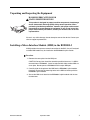
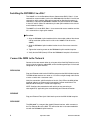
BSX8000-5 Broadband Services Switch Installation Instructions Document Number BSX8-A2-GZ40-00 September 2004 Contents Product Documentation Online .......................................................................... 2 Release Notes ................................................................................................... 2 BSX8000-5 Overview ........................................................................................ 2 Unpacking and Inspecting the Equipment ......................................................... 3 Installing a Micro Interface Module (MIM) in the BSX8000-5 ............................ 3 Installing the BSX8000-5 in a BAC .................................................................... 4 Connect the MIM to the Network ....................................................................... 4 BAC Management ............................................................................................. 5 LED Indicators ................................................................................................... 6 Regulatory Compliance for Class A Equipment ................................................. 7 Warranty, Sales, Service, and Training Information ........................................... 7 BSX8-A2-GZ40-00 September 2004 1 Product Documentation Online Complete documentation for Paradyne products is available at www.paradyne.com. Select Support → Technical Manuals. To order a paper copy of a Paradyne document, or to speak with a sales representative, please call 1-727-530-2000. Release Notes Release notes for this product are available in the subscriber firmware area of www.paradyne.com. Select Support → Subscriber Firmware. Always review the relevant release notes before installing a new card. BSX8000-5 Overview The BSX8000-5 Broadband Services Switch provides multi-gigabit Ethernet uplink support capability, full-nonblocking switching throughput, and enhanced management functionality for the 4000E and 12000E Broadband Access Concentrators (BACs). The BSX8000-5 supports four fixed 10/100/1000 RJ45 Ethernet interfaces and one MIM (Micro Interface Module) slot. Multiple MIM varieties are supported. The BSX8000-5 delivers a full 1 Gbps full duplex backplane connection to each access module in the BAC. This ensures that the aggregate access bandwidth cannot exceed the backplane speed of the chassis. When two BSX8000 modules are used in the 12000E, the backplane speed is doubled, providing a 2 Gbps connection to each access module. The BSX8000-5 supports the following access modules: AAM8000-24 AIM24000-48 EIM2000-12 EIM2000-24 SIM2000-24 TIM1500-12 TIM1500-24 The BSX8000-5 supports 576 DSL ports. 2 September 2004 BSX8-A2-GZ40-00 Unpacking and Inspecting the Equipment HANDLING PRECAUTIONS FOR ! STATIC-SENSITIVE DEVICES This product is designed to protect sensitive components from damage due to electrostatic discharge (ESD) during normal operation. When performing installation procedures, however, take proper static control precautions to prevent damage to equipment. If you are not sure of the proper static control precautions, contact your nearest sales or service representative. If there is any visible damage, do not attempt to connect the device. Contact your sales or support representative Installing a Micro Interface Module (MIM) in the BSX8000-5 A MIM provides the upstream network connection for the BAC. Any of Paradyne’s available MIM models may be installed on the BSX8000-5 uplink module. Procedure 1. Remove the cover plate from the MIM port. CAUTION: Cover plates should be stored for possible future use. If a MIM is removed from a BSX8000-5, it must be replaced with either another MIM or a cover plate. Do not operate a BSX8000-5 with an open MIM port. 2. Carefully slide the faceplate of the MIM into the BSX8000-5 uplink module faceplate. Ensure that the mounting holes on the MIM are lined up with the BSX8000-5 uplink module. 3. Secure the MIM circuit board to the BSX8000-5 uplink module with the two thumbscrews. BSX8-A2-GZ40-00 September 2004 3 Installing the BSX8000-5 in a BAC The 12000E is a 14-slot Broadband Access Concentrator (BAC). Slots 1–12 are reserved for access modules (such as the AIM24000-48) and slots U1 and U2 are reserved for uplink modules. Although not required for operational purposes, if redundancy is desired, two BSX8000-5 modules may be installed in the 12000E, in slots U1 and U2. (Note: For redundancy, the two uplink modules in the chassis must be identical models.) The 4000E is a five-slot BAC. Slots 1–4 are reserved for access modules and slot U1 is reserved for a single uplink module. Procedure 1. Align the BSX8000-5 uplink module with the slot module guides of the chosen slot for installation (either slot U1 or U2 on the 12000E or slot U1 on the 4000E). 2. Slide the BSX8000-5 uplink module into the chassis. Do not use excessive force. 3. Tighten the fastening screws on the BSX8000-5 uplink module faceplate. 4. Verify that the PWR (Power) LED on the BSX8000-5 faceplate is illuminated. Connect the MIM to the Network Connect to the core network either by using one of the fixed GigE interfaces or by using an interface from the added MIM, or from the Management port if it has been configured as an uplink interface. MIM-10/100 Plug your Ethernet cable into the RJ45 Ethernet port on the MIM-10/100 faceplate. The MIM-10/100 connects to a router or a PC with a straight-through cable and to a hub or a switch with a crossover cable. Verify the connection: solid illumination of the Lnk (link) LED on the MIM-10/100 faceplate indicates an Ethernet uplink connection has been established. The MIM-10/100 Ethernet port is 10/100 auto-negotiating. NOTE: Configure the remote device with which you are connecting to auto-negotiate (if applicable) prior to establishing your Ethernet connection. MIM100F Plug your Ethernet Fiber Optic Cable into the port on the MIM-10/100 faceplate. MIM-2000F The MIM-2000F is a two-port fiber gigabit Ethernet interface, which connects to the Fast Ethernet Bus of the BAC. This will function but is not recommended for use with the BSX8000-5 Uplink Interface. 4 September 2004 BSX8-A2-GZ40-00 MIM-4000F The MIM-4000F is a four-port fiber gigabit Ethernet interface connecting directly to the gigabit Ethernet switch in the BSX8000-5 uplink module. MIM-2E1 or MIM-4E1 Plug your E1 cable into one of the RJ45 E1 ports on the MIM-2E1 or MIM-4E1 faceplate. The MIM-2E1 or MIM-4E1 connects to an E1 network extender provider unit (ENE2000-P, ENE2000-P-12 or, for loop bonding, ENE2020-P) via a standard E1 line. Verify the connection: the Lnk (link) LED on the MIM-2E1 or MIM-4E1 faceplate flashes green to indicate a network connection has been established. MIM-2T1 Plug your T1 cable into one of the RJ45 T1 ports on the MIM-2T1 faceplate. The MIM-2T1 connects to a T1 network extender provider unit (TNE1500 or TNE1520) via a standard T1 line. Verify the connection: the Lnk (link) LED on the MIM-2T1 faceplate flashes green to indicate a network connection has been established. BAC Management The BSX8000-5 uplink module provides BAC management capability via the Command Line Interface (CLI), Simple Network Management Protocol (SNMP), and the web-based Network Management System (NMS). For access and configuration instructions, refer to the CLI Management User Guide and the NMS Management User Guide. BSX8-A2-GZ40-00 September 2004 5 LED Indicators Table 1. LED States and Meanings LED State Indication Additional Information PWR (Power) Solid green BSX8000-5 uplink module is receiving power Both BAC power terminals are connected. Pulsing green* BSX8000-5 uplink module is operational Both BAC power terminals are connected. It can take 5-10 seconds after a power-up or reboot, before the LED begins to pulse. Solid amber BSX8000-5 uplink module is receiving power Only one of the two BAC power terminals is connected. Pulsing amber* BSX8000-5 uplink module is operational Only one of the two BAC power terminals is connected. It can take 5-10 seconds after a power-up or reboot, before the LED begins to pulse. No illumination No power The BSX8000-5 uplink module is not receiving power (the BAC may or may not be receiving power). Solid green All fans are functioning All four of the fans on the BAC fan card are functioning. Solid amber Non-functioning fan At least one of the four fans on the BAC fan card is no longer functioning. Solid green Direct Ethernet management connection is established The Lnk LED applies only to direct physical connections with the MGMT port; it does not apply to uplink network connections or connections via the RS232 COM Port.The MGMT port is a 10/100 auto-negotiating Ethernet port. Flashing green* Traffic is flowing through the MGMT port At either 10 Mbps or 100 Mbps. No illumination No direct connection via the MGMT port is established Solid green MIM-10/100, MIM100F, MIM-2000F, MIM-4000F, uplink connection is established For further information regarding MIM LEDs, please refer to the corresponding MIM Installation Instructions. Flashing green* MIM-2T1, MIM-2E1, or MIM-4E1 uplink connection is established For further information regarding MIM LEDs, refer to the corresponding MIM Installation Instructions. No illumination No uplink connection is established Applicable to all MIM model types. Fan Lnk (Link) [MIM] Lnk (Link) * A pulsing LED blinks steadily at a rate of once per second. A flashing LED blinks at a more rapid, less constant rate. 6 September 2004 BSX8-A2-GZ40-00 Regulatory Compliance for Class A Equipment The following regulatory compliance information applies to a BSX8000-5 as installed in a Paradyne BAC. US Federal Communications Commission (FCC) NOTE: This equipment has been tested and found to comply with the limits for a Class A digital device, pursuant to part 15 of the FCC Rules. These limits are designed to provide reasonable protection against harmful interference when the equipment is operated in a commercial environment. This equipment generates, uses and can radiate radio frequency energy and, if not installed and used in accordance with the instruction manual, may cause harmful interference to radio communications. Operation of this equipment in a residential area is likely to cause harmful interference in which case the user will be required to correct the interference at his own expense. Caution: Changes or modifications not expressly approved by the manufacturer could void the user’s authority to operate the equipment. Industry Canada This Class A digital apparatus complies with Canadian ICES-003. Cet appareil numérique de la Classe A est conforme à la norme NMB-003 du Canada. Europe This Class A product complies with European Norm EN55022. Warning: In a domestic environment this product may cause radio interference in which case the user may be required to take adequate measures to correct the situation. Warranty, Sales, Service, and Training Information Contact your local sales representative, service representative, or distributor directly for any help needed. For additional information concerning warranty, sales, service, repair, installation, documentation, training, distributor locations, or Paradyne worldwide office locations, use one of the following methods: Internet: Visit the Paradyne World Wide Web site at www.paradyne.com. (Be sure to register your warranty at www.paradyne.com/warranty.) Telephone: Call our automated system to receive current information by fax or to speak with a company representative. — Within the U.S.A., call 1-800-870-2221 — Outside the U.S.A., call 1-727-530-2340 Copyright © 2004 Paradyne Corporation. Printed in U.S.A. BSX8-A2-GZ40-00 September 2004 7 ',. *BSX8-A2-GZ40-00* 8 September 2004 BSX8-A2-GZ40-00