1
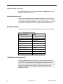
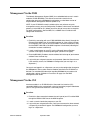
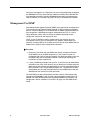
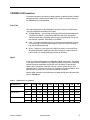
SIM2000-24 SDSL Inverse Multiplexer Installation Instructions Document Number SIM2-A2-GZ40-00 September 2004 Contents Software and Firmware License Agreement ...................................................... 2 Product Documentation Online .......................................................................... 3 Release Notes ................................................................................................... 3 Unpacking the SIM2000-24 ............................................................................... 4 Installation in a 4000 or 12000 BAC .................................................................. 4 Connecting the SDSL Line ................................................................................ 5 Default Settings ................................................................................................. 6 SIM2000-24 Management ................................................................................. 6 Management Via the NMS ................................................................................. 7 Management Via the CLI ................................................................................... 7 Management Via SNMP .................................................................................... 8 SIM2000-24 Parameters .................................................................................... 9 RAM and NVRAM .............................................................................................. 10 Configuration Backup and Restore .................................................................... 10 LED Indicators ................................................................................................... 11 Regulatory Compliance for Class A Equipment ................................................. 12 Important Safety Instructions ............................................................................. 12 Warranty, Sales, Service, and Training Information ........................................... 13 Document Feedback .......................................................................................... 13 Trademarks ........................................................................................................ 13 SIM2-A2-GZ40-00 September 2004 1 Software and Firmware License Agreement ONCE YOU HAVE READ THIS LICENSE AGREEMENT AND AGREE TO ITS TERMS, YOU MAY USE THE SOFTWARE AND/OR FIRMWARE INCORPORATED INTO THE PARADYNE PRODUCT. BY USING THE PARADYNE PRODUCT YOU SHOW YOUR ACCEPTANCE OF THE TERMS OF THIS LICENSE AGREEMENT. IN THE EVENT THAT YOU DO NOT AGREE WITH ANY OF THE TERMS OF THIS LICENSE AGREEMENT, PROMPTLY RETURN THE UNUSED PRODUCT IN ITS ORIGINAL PACKAGING AND YOUR SALES RECEIPT OR INVOICE TO THE LOCATION WHERE YOU OBTAINED THE PARADYNE PRODUCT OR THE LOCATION FROM WHICH IT WAS SHIPPED TO YOU, AS APPLICABLE, AND YOU WILL RECEIVE A REFUND OR CREDIT FOR THE PARADYNE PRODUCT PURCHASED BY YOU. The terms and conditions of this License Agreement (the “Agreement”) will apply to the software and/or firmware (individually or collectively the “Software”) incorporated into the Paradyne product (the “Product”) purchased by you and any derivatives obtained from the Software, including any copy of either. If you have executed a separate written agreement covering the Software supplied to you under this purchase, such separate written agreement shall govern. Paradyne Corporation (“Paradyne”) grants to you, and you (“Licensee”) agree to accept a personal, non-transferable, non-exclusive, right (without the right to sublicense) to use the Software, solely as it is intended and solely as incorporated in the Product purchased from Paradyne or its authorized distributor or reseller under the following terms and conditions: 1. Ownership: The Software is the sole property of Paradyne and/or its licensors. The Licensee acquires no title, right or interest in the Software other than the license granted under this Agreement. 2. Licensee shall not use the Software in any country other than the country in which the Product was rightfully purchased except upon prior written notice to Paradyne and an agreement in writing to additional terms. 3. The Licensee shall not reverse engineer, decompile or disassemble the Software in whole or in part. 4. The Licensee shall not copy the Software except for a single archival copy. 5. Except for the Product warranty contained in the manual, the Software is provided “AS IS” and in its present state and condition and Paradyne makes no other warranty whatsoever with respect to the Product purchased by you. THIS AGREEMENT EXPRESSLY EXCLUDES ALL OTHER WARRANTIES, WHETHER EXPRESS OR IMPLIED, OR ORAL OR WRITTEN, INCLUDING WITHOUT LIMITATION: a. Any warranty that the Software is error-free, will operate uninterrupted in your operating environment, or is compatible with any equipment or software configurations; and b. ANY AND ALL IMPLIED WARRANTIES, INCLUDING WITHOUT LIMITATION IMPLIED WARRANTIES OF MERCHANTABILITY, FITNESS FOR A PARTICULAR PURPOSE AND NON-INFRINGEMENT. Some states or other jurisdictions do not allow the exclusion of implied warranties on limitations on how long an implied warranty lasts, so the above limitations may not apply to you. This warranty gives you specific legal rights, 2 September 2004 SIM2-A2-GZ40-00 and you may also have other rights which vary from one state or jurisdiction to another. 6. In no event will Paradyne be liable to Licensee for any consequential, incidental, punitive or special damages, including any lost profits or lost savings, loss of business information or business interruption or other pecuniary loss arising out of the use or inability to use the Software, whether based on contract, tort, warranty or other legal or equitable grounds, even if Paradyne has been advised of the possibility of such damages, or for any claim by any third party. 7. The rights granted under this Agreement may not be assigned, sublicensed or otherwise transferred by the Licensee to any third party without the prior written consent of Paradyne. 8. This Agreement and the license granted under this Agreement shall be terminated in the event of breach by the Licensee of any provisions of this Agreement. 9. Upon such termination, the Licensee shall refrain from any further use of the Software and destroy the original and all copies of the Software in the possession of Licensee together with all documentation and related materials. 10. This Agreement shall be governed by the laws of the State of Florida, without regard to its provisions concerning conflicts of laws. Product Documentation Online Complete documentation for Paradyne products is available at www.paradyne.com. Select Support → Technical Manuals. To order a paper copy of a Paradyne document, or to speak with a sales representative, please call 1-727-530-2000. Release Notes Release notes for this product are available in the subscriber firmware area of www.paradyne.com. Select Support → Subscriber Firmware. Always review the relevant release notes before installing a new card. SIM2-A2-GZ40-00 September 2004 3 Unpacking the SIM2000-24 HANDLING PRECAUTIONS FOR ! STATIC-SENSITIVE DEVICES This product is designed to protect sensitive components from damage due to electrostatic discharge (ESD) during normal operation. When performing installation procedures, however, take proper static control precautions to prevent damage to equipment. If you are not sure of the proper static control precautions, contact your nearest sales or service representative. Unpack and inspect the SIM2000-24. If there is visible damage, do not attempt to connect the device; contact your sales or service representative. Installation in a 4000 or 12000 BAC There must be a Multiplexer Uplink Module (MUM) installed in the Broadband Access Concentrator (BAC) in order for interface modules to operate. The 12000 and 12000E BACs are fourteen slot chassis. Slots 1–12 are reserved for interface modules (such as the AIM24000), and the remaining slots (13 and 14 in the 12000 and U1 and U2 in the 12000E) are reserved for management modules. The 4000 BAC is a five slot chassis; slots 1–4 are reserved for interface modules and slot 5 is reserved for a MUM. Interface modules are hot swappable. Installing or removing an interface module while the chassis is powered up does not affect the operational status of other interface modules within the chassis. Procedure 1. Align the SIM2000-24 with the slot module guides of the chosen slot for installation (slot 1–12 in the 12000 and 12000E or slot 1–4 in the 4000 and 4000E). 2. Slide the SIM2000-24 into the chassis. Do not use excessive force. 3. Secure the SIM2000-24 by tightening the fastening screws on the module faceplate. 4. Verify that the PWR (Power) LED on the SIM2000-24 faceplate is illuminated. 4 September 2004 SIM2-A2-GZ40-00 Connecting the SDSL Line Plug the SDSL cable RJ21 connector into the corresponding RJ21 port on the back of the IP DSLAM. For most applications, a SIM2000-24 SDSL link requires a straight-through cable. The SIM2000-24 can be connected with a remote SDSL subscriber unit via either a single SDSL line or double SDSL lines (loop bonding). For each port being connected to a remote SDSL subscriber unit, verify that the SDSL link has been established: the SDSL LK LED for that port will pulse green to indicate the connection has been made. Link up time can vary from one to five minutes depending on the quality, gauge and distance of the copper cables. Table 1. SDSL RJ21 Pinouts Port Connector Pins (Ring, Tip) Port Connector Pins (Ring, Tip) Port 1 1, 26 Port 13 13, 38 Port 2 2, 27 Port 14 14, 39 Port 3 3, 28 Port 15 15, 40 Port 4 4, 29 Port 16 16, 41 Port 5 5, 30 Port 17 17, 42 Port 6 6, 31 Port 18 18, 43 Port 7 7, 32 Port 19 19, 44 Port 8 8, 33 Port 20 20, 45 Port 9 9, 34 Port 21 21, 46 Port 10 10, 35 Port 22 22, 47 Port 11 11, 36 Port 23 23, 48 Port 12 12, 37 Port 24 24, 49 Pins 25 and 50 are not used. Loop Bonded SDSL Connection Using two SDSL lines for one network connection (loop bonding) will net twice the speed and data passing capability as a single-line SDSL connection. A second SDSL line can also be considered a backup for the first, and vice versa, should either line become disabled. Any two SIM2000-24 ports (consecutive or not) may be connected to an SNE2020-S or SNE2020G-S subscriber unit to establish a loop bonded connection. NOTE: Any ports on the SIM2000-24 intended for a loop bonded connection with an SNE2020-S or SNE2020G-S should be identically configured prior to connection. Bonding ports with different configurations will likely result in misplaced, misdirected, or dropped data. See the NMS Management User Guide or the CLI and SNMP Management User Guide for configuration instructions. If default settings are to be used for both ports, then prior configuration is not necessary and you may proceed with installation. SIM2-A2-GZ40-00 September 2004 5 Single Line SDSL Connection A single line connection can be established between a SIM2000-24 and any of Paradyne’s SDSL subscriber units. Bandwidth and Line Code There are nine bandwidth options for SIM2000-24 SDSL connections. Distance capabilities vary, dependent upon the type of line code being utilized. The defaults are TC/PAM line encoding (G.SHDSL) at 272 kbps. See SIM2000-24 Parameters on page 9 for more detailed information regarding bandwidth and line code. Default Settings No configuration is necessary for the SIM2000-24 to operate at default settings. Table 2. SIM2000-24 Default Settings Configuration Option Default Backbone-VLAN 0 (off) Circ. ID (Circuit Indentification) n/a (no default) Flood Upl (Uplink) IP Range 1 0.0.0.0 – 255.255.255.255 IP Range 2 0.0.0.0 – 0.0.0.0 Line Code TC/PAM (G.SHDSL) Pri (VLAN Priority) 0 (none) Protocol All Speed: 272 kbps VLAN Ranges (1–10) 0 – 0 (off) SIM2000-24 Management Once the SIM2000-24 has been installed, line code, bandwidth and all other configurations are software selectable. Dependent upon the MUM model installed in your DSLAM, the SIM2000-24 can be configured via the Command Line Interface (CLI), Simple Network Management Protocol (SNMP), or the web-based Network Management System (NMS). For further information regarding SIM2000-24 management and configuration please refer to the NMS, CLI, and SNMP User’s Guides. 6 September 2004 SIM2-A2-GZ40-00 Management Via the NMS The Network Management System (NMS) is an embedded web server in certain models of IP DSLAM MUMs. This web server maintains statistical and configuration data for the SIM2000-24 and includes a scaled-down version of Simple Network Management Protocol (SNMP v1.0). NOTE: If your IP DSLAM is newly installed and has not yet been set up for management access, you must configure the IP address, subnet mask and default gateway (via the NMS or CLI) before you will be able to access data or complete any other configurations. See the NMS, CLI, or SNMP User’s Guide for initial configuration instructions. Procedure 1. Establish a connection with your IP DSLAM MUM either directly (through the Ethernet RJ45 MGMT Port on the MUM faceplate) or, if the system has been so configured, from a PC on your local network. For direct connections, verify that the MGMT LNK LED on the MUM faceplate is illuminated (indicating the connection has been established). 2. Launch a web browser on your PC such as Microsoft Internet Explorer (version 4.0 or higher) or Netscape Navigator (version 4.0 or higher). 3. Enter the DSLAM's IP address into the address field at the top of your browser window. Press the Enter key. 4. Log in with your assigned username and password. (Note that General users have read-only access; for SIM2000-24 configuration you must log in as a Superuser.) Once you have logged in as a Superuser, you may make configuration changes to the SIM2000-24, and any other interface modules installed in the IP DSLAM, as desired. For more detailed information regarding SIM2000-24 parameters and configuration, refer to SIM2000-24 Parameters on page 9, or the NMS Management User Guide. Management Via the CLI Interface modules in an IP DSLAM with a Command Line Interface (CLI) compatible MUM can be managed with a terminal emulation program loaded onto your PC using commands entered at a command prompt. Procedure 1. Establish a direct connection between the serial port of your PC and the MUM through the RS232 COM Port on the MUM faceplate. 2. Launch a terminal emulation program on your PC. 3. Log in with your assigned username. Once your username has been entered, a request for password will appear. For SIM2000-24 configuration you must log in as a Superuser. SIM2-A2-GZ40-00 September 2004 7 Once you have logged in as a Superuser, you may make configuration changes to the SIM2000-24 and any other interface modules installed in the IP DSLAM. For more detailed information regarding SIM2000-24 parameters and configuration, refer to SIM2000-24 Parameters on page 9, or the CLI or SNMP User’s Guides. Management Via SNMP Simple Network Management Protocol (SNMP) is the standard for management of Transmission Control Protocol/Internet Protocol (TCP/IP) networks and network devices. Interface modules in an IP DSLAM with an SNMP compatible MUM can be managed with a MIB Browser program (loaded onto your PC) via a set of Object Identifiers (OIDs). OIDs are strings of numbers specifying various configuration commands and requests for data. NOTE: If your IP DSLAM is newly installed and has not yet been set up for management access, you must configure the IP Address, Subnet Mask and Gateway (via either NMS or CLI) before you will be able to utilize SNMP. See the SNMP User’s Guide for initial configuration instructions. Procedure 1. Establish a connection with the MUM either directly (through the Ethernet RJ45 MGMT port on the MUM faceplate) or, if the system has been so configured, from a PC on your local network. For direct connections verify that the MGMT LNK LED on the MUM faceplate is illuminated (indicating the connection has been established). 2. Launch a MIB Browser program on your PC. If you have not yet downloaded the MIBs to your PC or local network, you can obtain the Paradyne enterprise MIBs from ftp://ftp.nettonet.com/download/mibs and the supported portions of MIB-II from RFC 1213 at http://www.ietf.org/rfc.html . Once these have been downloaded, you will need to compile them into your MIB Browser. See your MIB Browser user manual for further instruction. Once the MIBs have been downloaded, you will be able to make configuration changes to the SIM2000-24 and any other interface modules installed in the IP DSLAM. For more detailed information regarding SIM2000-24 parameters and configuration, refer to SIM2000-24 Parameters on page 9, or the SNMP User’s Guide. 8 September 2004 SIM2-A2-GZ40-00 SIM2000-24 Parameters Parameters common to all interface module models are defined in both the NMS Management User’s Guide and the SNMP User’s Guide. Parameters specific to the SIM2000-24 are outlined below. Line Code Line code configuration for the SIM2000-24 applies to all ports; individual ports cannot be configured with different line codes. TC/PAM (Default) – Transmission Convergence/Pulse Amplitude Modulation (TC/PAM) line code is a sixteen-level PAM technique which incorporates advanced trellis code, precoding, spectral shaping, equalization circuits and forward error correction. Also known as G.SHDSL. CAP – Carrierless Amplitude and Phase (CAP) line code modulates transmit and receive signals into two wide-frequency bands that can pass through a filter without being attenuated. 2B1Q – Two Binary, One Quaternary (2B1Q) line code is a four-level Pulse Amplitude Modulation (PAM) technique which reduces the signaling rate to half of the bit rate, thereby doubling transmission efficiency. Speed There are nine bandwidth options for SIM2000-24 SDSL connections. The default is 272 kbps. Distance capabilities vary, depending upon the type of line code being utilized. Distances listed below assume the use of 26 American Wire Gauge (AWG) cable. Connections made with cable of a greater gauge will link up at greater distances. The units may not link up if the cable is in poor condition or if the cable distance is greater than a particular bandwidth will support. Remote SDSL subscriber units determine line speed through their communication with the SIM2000-24. Table 3. SDSL Distance Capabilities BANDWIDTH kbps 2,320 2,064 1,552 1,040 784 G.SHDSL Distance Feet 11,300 12,200 12,800 16,000 16,800 3,444 3,719 3,901 4,877 5,121 11,000 11,900 12,600 15,500 16,000 3,353 3,627 3,840 4,724 4,877 10,400 10,800 13,400 14,800 15,800 3,170 3,292 4,084 4,511 4,816 Meters CAP Distance Feet Meters 2B1Q Distance Feet Meters SIM2-A2-GZ40-00 September 2004 528 272 144 18,400 19,400 20,200 25,400 5,608 400 6,157 7,742 17,900 18,900 23,100 24,700 5,456 5,913 7,041 7,529 17,400 18,200 19,200 23,800 5,304 5,761 5,547 5,852 7,254 9 RAM and NVRAM Configuration backup is inherent in the SIM2000-24. Upon initial power-up of the IP DSLAM, default parameters of the SIM2000-24 will remain in place unless changed through the NMS, CLI, or SNMP. Once changed, new configurations will automatically be recorded in both the Random Access Memory (RAM) of the SIM2000-24 and the Non-Volatile Random Access Memory (NVRAM) of the MUM. While data stored in SIM2000-24 RAM will be erased if the module is removed from the IP DSLAM or the IP DSLAM loses power, interface module data stored within MUM NVRAM will remain intact, even if the unit loses power, unless deliberately cleared or reconfigured. Configuration Backup and Restore Individual port configurations can be saved locally on your PC as a backup, and/or for use as a template for future configurations. Once the SIM2000-24 has been configured as desired, the settings can be uploaded through a Trivial File Transfer Protocol (TFTP) tool with a GET command and the following information: Host name: [IP DSLAM IP Address] Remote filename: NVR_CFG.bin.[superuser password] Local filename: [user preference] Port configuration files can be downloaded from a local file to a SIM2000-24, using the SET command. NOTE: Only individual port configurations can be saved to a local file. Chassis configurations cannot be uploaded or downloaded; they must be manually configured for each unit. 10 September 2004 SIM2-A2-GZ40-00 LED Indicators Table 4. LED Indicators LED STATE INDICATION ADDITIONAL INFORMATION PWR (Power) Solid green SIM2000-24 is operational If the Power LED is not illuminated, it is unlikely the SIM2000-24 is receiving power. None of the LEDs will be illuminated. SDSL LK (Link) Pulsing green* SDSL connection is established and active The SDSL link is operational and traffic is flowing. Solid green Problematic SDSL connection A connection exists but there is indication of a problem with the SDSL line. No illumination No SDSL connection Flashing amber SDSL activity The port is receiving either data from the remote SDSL subscriber unit or statistical packets from the IP DSLAM management. Solid amber Heavy Rx traffic The port is receiving large amounts of data from the remote SDSL subscriber unit. No illumination No activity A link may exist but the port is not receiving any data from the remote SDSL subscriber unit. Flashing amber SDSL activity The port is transmitting data to the remote SDSL subscriber unit. Solid amber Heavy Tx traffic The port is transmitting large amounts of data to the remote SDSL subscriber unit. No illumination No activity A link may exist but the port is not transmitting any data to the remote SDSL subscriber unit. SDSL RX (Receiving) SDSL TX (Transmitting) * A pulsing LED blinks steadily at a rate of once per second. A flashing LED blinks at a more rapid, less constant rate. SIM2-A2-GZ40-00 September 2004 11 Regulatory Compliance for Class A Equipment US Federal Communications Commission (FCC) Note: This equipment has been tested and found to comply with the limits for a Class A digital device, pursuant to part 15 of the FCC Rules. These limits are designed to provide reasonable protection against harmful interference when the equipment is operated in a commercial environment. This equipment generates, uses and can radiate radio frequency energy and, if not installed and used in accordance with the instruction manual, may cause harmful interference to radio communications. Operation of this equipment in a residential area is likely to cause harmful interference in which case the user will be required to correct the interference at his own expense. Caution: Changes or modifications not expressly approved by the manufacturer could void the user’s authority to operate the equipment. Industry Canada This Class A digital apparatus complies with Canadian ICES-003. Cet appareil numérique de la Classe A est conforme à la norme NMB-003 du Canada. Europe This Class A product complies with European Norm EN55022. Caution: In a domestic environment this product may cause radio interference in which case the user may be required to take adequate measures to correct the situation. ! Important Safety Instructions ! UNITED STATES – EMI NOTICE: This equipment has been tested and found to comply with the limits for a Class A digital device, pursuant to Part 15 of the FCC rules. These limits are designed to provide reasonable protection against harmful interference when the equipment is operated in a commercial environment. This equipment generates, uses, and can radiate radio frequency energy and, if not installed and used in accordance with the instruction manual, may cause harmful interference to radio communications. Operation of this equipment in a residential area is likely to cause harmful interference in which case the user will be required to correct the interference at his own expense. The authority to operate this equipment is conditioned by the requirements that no modifications will be made to the equipment unless the changes or modifications are expressly approved by Paradyne Corporation. 12 September 2004 SIM2-A2-GZ40-00 ! CANADA – EMI NOTICE: This Class A digital apparatus meets all requirements of the Canadian interference-causing equipment regulations. Cet appareil numérique de la classe A respecte toutes les exigences du règlement sur le matérial brouilleur du Canada. Warranty, Sales, Service, and Training Information Contact your local sales representative, service representative, or distributor directly for any help needed. For additional information concerning warranty, sales, service, repair, installation, documentation, training, distributor locations, or Paradyne worldwide office locations, use one of the following methods: Internet: Visit the Paradyne World Wide Web site at www.paradyne.com. (Be sure to register your warranty at www.paradyne.com/warranty.) Telephone: Call our automated system to receive current information by fax or to speak with a company representative. — Within the U.S.A., call 1-800-870-2221 — Outside the U.S.A., call 1-727-530-2340 Document Feedback We welcome your comments and suggestions about this document. Please mail them to Technical Publications, Paradyne Corporation, 8545 126th Ave. N., Largo, FL 33773, or send e-mail to [email protected]. Include the number and title of this document in your correspondence. Please include your name and phone number if you are willing to provide additional information. Trademarks Hotwire is a registered trademark of Paradyne Corporation. All other products and services mentioned herein are the trademarks, service marks, registered trademarks, or registered service marks of their respective owners. Copyright © 2004 Paradyne Corporation. Printed in U.S.A. SIM2-A2-GZ40-00 September 2004 13 '!. *SIM2-A2-GZ40-00* 14 September 2004 SIM2-A2-GZ40-00