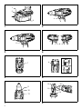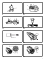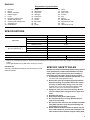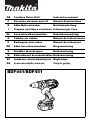
1
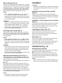
GB
Cordless Driver Drill
Instruction manual
F
Perceuse-visseuse sans fil
Manuel d’instructions
D
Akku-Bohrschrauber
Betriebsanleitung
I
Trapano avvitatore a batteria Istruzioni per l’uso
NL
Accuschroefboormachine
Gebruiksaanwijzing
E
Taladro sin cables
Manual de instrucciones
P
Berbegvim sem cabos
Manual de instruções
Akku bore-skruemaskine
Brugsanvisning
S
Sladdlös skruvdragare
Bruksanvisning
N
Batteridrevet boreskrutrekker Bruksanvisning
SF
Johdoton ruuvinväännin/pora Käyttöohje
GR
Δραπανοκατσάβιδο μπαταρίας
DK
BDF441/BDF451
Οδηγίες χρήσης
1
2
4
3
1
2
A
5
B
6
3
4
8
7
5
6
12
16
9
13
10
15
14
11
7
2
8
18
17
19
9
10
20
16
21
11
12
23
24
22
13
14
25
26
15
28
27
16
3
29
30
17
4
ENGLISH
Explanation of general view
1.
2.
3.
4.
5.
6.
7.
8.
9.
10.
Red part
Button
Battery cartridge
Switch trigger
Lamp
Reversing switch lever
Speed change lever
Action mode change lever
Adjusting ring
Graduations
11.
12.
13.
14.
15.
16.
17.
18.
19.
20.
Arrow
Steel band
Grip base
Side grip
Protrusion
Groove
Sleeve
Bit holder
Bit
Screw
21.
22.
23.
24.
25.
26.
27.
28.
29.
30.
Hook
Limit mark
Rear cover
Screws
Arm
Spring
Recesed part
Carbon brush cap
Hole
Carbon brush cap
SPECIFICATIONS
Model
Capacities
No load speed (min-1)
BDF441
BDF451
Steel
13 mm
13 mm
Wood
50 mm
65 mm
Wood screw
6 mm x 75 mm
10 mm x 89 mm
Machine screw
6 mm
High (2)
0 – 1,700
Medium (2)
0 – 600
Low (1)
0 – 300
Overall length
238 mm
Net weight
2.0 kg
2.1 kg
Rated voltage
D.C. 14.4 V
D.C. 18 V
• Due to our continuing program of research and development, the specifications herein are subject to change without
notice.
• Note: Specifications may differ from country to country.
Intended use
The tool is intended for drilling and screw driving in wood,
metal and plastic.
SPECIFIC SAFETY RULES
DO NOT let comfort or familiarity with product (gained
from repeated use) replace strict adherence to drill
safety rules. If you use this power tool unsafely or
incorrectly, you can suffer serious personal injury.
1. Use auxiliary handles supplied with the tool. Loss
of control can cause personal injury.
2. Hold power tools by insulated gripping surfaces
when performing an operation where the cutting
tool may contact hidden wiring or its own cord.
Contact with a “live” wire will make exposed metal
parts of the tool “live” and shock the operator.
3. Always be sure you have a firm footing. Be sure
no one is below when using the tool in high locations.
4. Hold the tool firmly.
5. Keep hands away from rotating parts.
6. Do not leave the tool running. Operate the tool
only when hand-held.
7. Do not touch the drill bit or the workpiece immediately after operation; they may be extremely hot
and could burn your skin.
8. Some material contains chemicals which may be
toxic. Take caution to prevent dust inhalation and
skin contact. Follow material supplier safety data.
5
SAVE THESE INSTRUCTIONS
WARNING:
MISUSE or failure to follow the safety rules stated in
this instruction manual may cause serious personal
injury.
IMPORTANT SAFETY
INSTRUCTIONS FOR BATTERY
CARTRIDGE
1. Before using battery cartridge, read all instructions and cautionary markings on (1) battery
charger, (2) battery, and (3) product using battery.
2. Do not disassemble battery cartridge.
3. If operating time has become excessively shorter,
stop operating immediately. It may result in a risk
of overheating, possible burns and even an explosion.
4. If electrolyte gets into your eyes, rinse them out
with clear water and seek medical attention right
away. It may result in loss of your eyesight.
5. Do not short the battery cartridge:
(1) Do not touch the terminals with any conductive material.
(2) Avoid storing battery cartridge in a container
with other metal objects such as nails, coins,
etc.
(3) Do not expose battery cartridge to water or
rain.
A battery short can cause a large current flow,
overheating, possible burns and even a breakdown.
6. Do not store the tool and battery cartridge in locations where the temperature may reach or exceed
50°C (122°F).
7. Do not incinerate the battery cartridge even if it is
severely damaged or is completely worn out. The
battery cartridge can explode in a fire.
8. Be careful not to drop or strike battery.
SAVE THESE INSTRUCTIONS
Tips for maintaining maximum battery life
1. Charge the battery cartridge before completely
discharged. Always stop tool operation and
charge the battery cartridge when you notice less
tool power.
2. Never recharge a fully charged battery cartridge.
Overcharging shortens the battery service life.
3. Charge the battery cartridge with room temperature at 10°C - 40°C (50°F - 104°F). Let a hot battery
cartridge cool down before charging it.
FUNCTIONAL DESCRIPTION
CAUTION:
• Always be sure that the tool is switched off and the battery cartridge is removed before adjusting or checking
function on the tool.
6
Installing or removing battery cartridge
(Fig. 1)
• Always switch off the tool before insertion or removal of
the battery cartridge.
• To remove the battery cartridge, withdraw it from the
tool while sliding the button on the side of the cartridge.
• To insert the battery cartridge, align the tongue on the
battery cartridge with the groove in the housing and slip
it into place. Always insert it all the way until it locks in
place with a little click. If you can see the red part on
the upper side of the button, it is not locked completely.
Insert it fully until the red part cannot be seen. If not, it
may accidentally fall out of the tool, causing injury to
you or someone around you.
• Do not use force when inserting the battery cartridge. If
the cartridge does not slide in easily, it is not being
inserted correctly.
Switch action (Fig. 2)
CAUTION:
• Before inserting the battery cartridge into the tool,
always check to see that the switch trigger actuates
properly and returns to the “OFF” position when
released.
To start the tool, simply pull the switch trigger. Tool speed
is increased by increasing pressure on the switch trigger.
Release the switch trigger to stop.
Lighting up the front lamp (Fig. 3)
CAUTION:
• Do not look in the light or see the source of light
directly.
Pull the switch trigger to light up the lamp. The lamp
keeps on lighting while the switch trigger is being pulled.
The lamp goes out 10 -15 seconds after releasing the trigger.
NOTE:
• Use a dry cloth to wipe the dirt off the lens of lamp. Be
careful not to scratch the lens of lamp, or it may lower
the illumination.
Reversing switch action (Fig. 4)
This tool has a reversing switch to change the direction of
rotation. Depress the reversing switch lever from the A
side for clockwise rotation or from the B side for counterclockwise rotation.
When the reversing switch lever is in the neutral position,
the switch trigger cannot be pulled.
CAUTION:
• Always check the direction of rotation before operation.
• Use the reversing switch only after the tool comes to a
complete stop. Changing the direction of rotation
before the tool stops may damage the tool.
• When not operating the tool, always set the reversing
switch lever to the neutral position.
Speed change (Fig. 5)
This tool has a three-gear speed change lever. To change
the speed, first switch off the tool and then slide the speed
change lever to the “1” position for low speed, “2” position
for medium speed or “3” position for high speed. Be sure
that the speed change lever is set to the correct position
before operation. Use the right speed for your job.
NOTE:
• When changing the position from “1” to “3” or from “3”
to “1”, it may be a little difficult to slide the speed
change lever. At this time, switch on and run the tool for
a second at the “2” position, then stop the tool and slide
to your desired position.
CAUTION:
• Always set the speed change lever fully to the correct
position. If you operate the tool with the speed change
lever positioned halfway between the “1” position, “2”
position and “3” position, the tool may be damaged.
• Do not use the speed change lever while the tool is
running. The tool may be damaged.
Selecting action mode (Fig. 6)
This tool has an action mode change lever. For drilling,
slide the action mode change lever to the left ( symbol).
For screwing, slide the action mode change lever to the
right ( symbol).
NOTE:
• When changing the position from “ ” to “ ”, it may be
a little difficult to slide the mode change lever. At this
time, switch on and run the tool for a second at the “ ”
position, then stop the tool and slide to your desired
position.
CAUTION:
• Always slide the action mode change lever all the way
to your desired mode position. If you operate the tool
with the lever positioned halfway between the mode
symbols, the tool may be damaged.
• Do not use the action mode change lever while the tool
is running. The tool may be damaged.
Adjusting the fastening torque (Fig. 7)
The fastening torque can be adjusted in 16 steps by turning the adjusting ring so that its graduations are aligned
with the pointer on the tool body.
First, slide the action mode change lever to the position of
symbol.
ASSEMBLY
CAUTION:
• Always be sure that the tool is switched off and the battery cartridge is removed before carrying out any work
on the tool.
Installing side grip (auxiliary handle)
(Fig. 8)
Always use the side grip to ensure operating safety.
Insert the side grip so that the protrusions on the grip base
fit in between the grooves on the tool barrel. Then tighten
the grip by turning clockwise.
Installing or removing driver bit or drill bit
(Fig. 9)
Turn the sleeve counterclockwise to open the chuck jaws.
Place the bit in the chuck as far as it will go. Turn the
sleeve clockwise to tighten the chuck. To remove the bit,
turn the sleeve counterclockwise.
Installing bit holder (Fig. 10)
Fit the bit holder into the protrusion at the tool foot on
either right or left side and secure it with a screw.
When not using the driver bit, keep it in the bit holders.
Bits 45 mm long can be kept there.
Hook (Fig. 11)
The hook is convenient for temporarily hanging the tool.
This can be installed on either side of the tool.
To install the hook, insert it into a groove in the tool housing on either side and then secure it with a screw. To
remove, loosen the screw and then take it out.
OPERATION (Fig. 12)
Screwdriving operation
First, slide the action mode change lever to the position of
symbol and select the fastening torque.
Place the point of the driver bit in the screw head and
apply pressure to the tool. Start the tool slowly and then
increase the speed gradually. Release the switch trigger
as soon as the clutch cuts in.
NOTE:
• Make sure that the driver bit is inserted straight in the
screw head, or the screw and/or bit may be damaged.
The fastening torque is minimum when the number 1 is
aligned with the pointer, and maximum when the marking
is aligned with the pointer. The clutch will slip at various
torque levels when set at the number 1 to 16. Before
actual operation, drive a trial screw into your material or a
piece of duplicate material to determine which torque level
is required for a particular application.
NOTE:
• The adjusting ring does not lock when the pointer is
positioned only halfway between the graduations.
7
• When driving wood screws, predrill pilot holes to make
driving easier and to prevent splitting of the workpiece.
See the chart.
Nominal diameter of wood Recommended size of pilot
screw (mm)
hole (mm)
3.1
2.0 - 2.2
3.5
2.2 - 2.5
3.8
2.5 - 2.8
4.5
2.9 - 3.2
4.8
3.1 - 3.4
5.1
3.3 - 3.6
5.5
3.7 - 3.9
5.8
4.0 - 4.2
6.1
4.2 - 4.4
• If the tool is operated continuously until the battery cartridge has discharged, allow the tool to rest for 15 minutes before proceeding with a fresh battery.
Drilling operation
First, slide the action mode change lever to the position of
symbol.
Drilling in wood
When drilling in wood, the best results are obtained with
wood drills equipped with a guide screw. The guide screw
makes drilling easier by pulling the bit into the workpiece.
Drilling in metal
To prevent the bit from slipping when starting a hole, make
an indentation with a center-punch and hammer at the
point to be drilled. Place the point of the bit in the indentation and start drilling.
Use a cutting lubricant when drilling metals. The exceptions are iron and brass which should be drilled dry.
CAUTION:
• Pressing excessively on the tool will not speed up the
drilling. In fact, this excessive pressure will only serve
to damage the tip of your bit, decrease the tool performance and shorten the service life of the tool.
• There is a tremendous force exerted on the tool/bit at
the time of hole break through. Hold the tool firmly and
exert care when the bit begins to break through the
workpiece.
• A stuck bit can be removed simply by setting the
reversing switch to reverse rotation in order to back
out. However, the tool may back out abruptly if you do
not hold it firmly.
• Always secure small workpieces in a vise or similar
hold-down device.
• If the tool is operated continuously until the battery cartridge has discharged, allow the tool to rest for 15 minutes before proceeding with a fresh battery.
8
MAINTENANCE
CAUTION:
• Always be sure that the tool is switched off and the battery cartridge is removed before attempting to perform
inspection or maintenance.
Replacing carbon brushes
Replace when they wear down to the limit mark. Keep the
carbon brushes clean and free to slip in the holders. Both
carbon brushes should be replaced at the same time. Use
only identical carbon brushes. (Fig. 13)
Use a screwdriver to remove two screws then remove the
rear cover. (Fig. 14)
Raise the arm part of the spring and then place it in the
recessed part of the housing with a slotted bit screwdriver
of slender shaft or the like. (Fig. 15)
Use pliers to remove the carbonbrush caps of the carbon
brushes. Take out the worn carbon brushes, insert the
new ones and replace the carbonbrush caps in reverse.
(Fig. 16)
Make sure that the carbonbrush caps have fit into the
holes in brush holders securely. (Fig. 17)
Reinstall the rear cover and tighten two screws securely.
To maintain product SAFETY and RELIABILITY, repairs,
any other maintenance or adjustment should be performed by Makita Authorized Service Centers, always
using Makita replacement parts.
ACCESSORIES
CAUTION:
• These accessories or attachments are recommended
for use with your Makita tool specified in this manual.
The use of any other accessories or attachments might
present a risk of injury to persons. Only use accessory
or attachment for its stated purpose.
If you need any assistance for more details regarding
these accessories, ask your local Makita service center.
•
•
•
•
•
•
•
•
Drill bits
Screw bits
Hook
Grip assembly
Various type of Makita genuine batteries and chargers
Rubber pad assembly
Wool bonnet
Foam polishing pad
NEDERLANDS
Verklaring van het onderdelenoverzicht
1.
2.
3.
4.
5.
6.
7.
8.
9.
10.
Rode deel
Knop
Accu
Aan/uit-schakelaar
Lamp
Omkeerschakelaar
Snelheidsinstelknop
Werkingsfunctie-instelknop
Instelring
Schaalverdeling
11.
12.
13.
14.
15.
16.
17.
18.
19.
20.
Pijlpunt
Metalen klemband
Basis van de zijhandgreep
Zijhandgreep
Uitsteeksel
Groef
Mof
Bithouder
Bit
Schroef
21.
22.
23.
24.
25.
26.
27.
28.
29.
30.
Haak
Slijtgrensmarkering
Achterkap
Schroeven
Arm
Veer
Verdiept gedeelte
Koolborstelkap
Opening
Koolborstelkap
TECHNISCHE GEGEVENS
Model
Capaciteiten
BDF441
BDF451
Metaal
13 mm
13 mm
Hout
50 mm
65 mm
Houtschroef
6 mm x 75 mm
10 mm x 89 mm
Machineschroef
6 mm
Hoog (3)
0 – 1700
Onbelaste snelheid (min-1)
Normaal (2)
0 – 600
Laag (1)
0 – 300
Totale lengte
238 mm
Netto gewicht
2,0 kg
2,1 kg
Nominale spanning
14,4 V gelijkstroom
18 V gelijkstroom
• Als gevolg van ons doorlopende onderzoeks- en ontwikkelingsprogramma, zijn de technische gegevens van dit
gereedschap onderhevig aan veranderingen zonder voorafgaande kennisgeving.
• Opmerking: De technische gegevens kunnen van land tot land verschillen.
Gebruiksdoeleinden
Het gereedschap is bedoeld voor boren en schroeven in
hout, metaal en kunststof.
AANVULLENDE
VEILIGHEIDSVOORSCHRIFTEN
Laat u NIET misleiden door een vals gevoel van
comfort en bekendheid met het gereedschap (na
veelvuldig gebruik) en neem alle
veiligheidsvoorschriften van de schroefboormachine
altijd strikt in acht. Bij onveilig of verkeerd gebruik
van het elektrisch gereedschap, bestaat de kans op
ernstig persoonlijk letsel.
1. Gebruik de hulphandgrepen die bij het
gereedschap werden geleverd. Als u de controle
over het gereedschap verliest, kan dit leiden tot
ernstig persoonlijk letsel.
2. Houd elektrisch gereedschap vast aan het
geïsoleerde oppervlak van de handgrepen
wanneer u werkt op plaatsen waar het
zaaggereedschap met verborgen bedrading of zijn
eigen snoer in aanraking kan komen. Door contact
met onder spanning staande draden, zullen de nietgeïsoleerde metalen delen van het gereedschap
onder spanning komen te staan zodat de gebruiker
een elektrische schok kan krijgen.
3. Zorg er altijd voor dat u stevig staat. Zorg ervoor
dat er niemand zich onder u bevindt wanneer u het
gereedschap op een hoge plaats gebruikt.
4. Houd het gereedschap stevig vast.
24
5. Houd uw handen uit de buurt van draaiende delen.
6. Laat het gereedschap niet ingeschakeld liggen.
Bedien het gereedschap alleen wanneer u het
vasthoudt.
7. Raak het schroef- of boorbit en het werkstuk niet
onmiddellijk na gebruik aan. Zij kunnen bijzonder
heet zijn en brandwonden op uw huid
veroorzaken.
8. Sommige materialen bevatten chemische stoffen
die giftig kunnen zijn. Neem
voorzorgsmaatregelen tegen het inademen van
stof en contact met de huid. Volg de
veiligheidsinstructies van de leverancier van het
materiaal op.
BEWAAR DEZE
VOORSCHRIFTEN
WAARSCHUWING:
VERKEERD GEBRUIK of het niet volgen van de
veiligheidsinstructies in deze gebruiksaanwijzing kan
leiden tot ernstig persoonlijk letsel.
BELANGRIJKE
VEILIGHEIDSINSTRUCTIES VOOR
ACCU’S
1. Alvorens de accu in gebruik te nemen, leest u
eerst alle instructies en
waarschuwingsopschriften op (1) de acculader, (2)
de accu en (3) het apparaat waarin de accu wordt
aangebracht.
2. Haal de accu niet uit elkaar.
3. Als de gebruikstijd aanzienlijk korter is geworden,
stopt u onmiddellijk met het gebruik. Anders kan
dit leiden tot kans op oververhitting, mogelijke
brandwonden en zelfs een explosie.
4. Als de elektrolyt in uw ogen komt, wast u deze uit
met schoon water en raadpleegt u onmiddellijk
een arts. Dit kan leiden tot verlies van
gezichtsvermogen.
5. Sluit de accu niet kort:
(1) Raak de accupolen niet aan met enig geleidend
materiaal.
(2) Bewaar de accu niet op een plaats waar deze in
aanraking kan komen met andere metalen
voorwerpen, zoals spijkers, munten, enz.
(3) Stel de accu niet bloot aan water of regen.
Kortsluiting van de accu kan leiden tot een hoge
stroomsterke, oververhitting, mogelijke
brandwonden en zelfs een defect.
6. Bewaar het gereedschap en de accu niet op
plaatsen waar de temperatuur kan oplopen tot
50 °C of hoger.
7. Werp de accu niet in een vuur, zelfs niet als deze al
ernstig beschadigd of helemaal versleten is. De
accu kan in een vuur exploderen.
8. Wees voorzichtig dat u de accu niet laat vallen of
ergens tegenaan stoot.
BEWAAR DEZE
VOORSCHRIFTEN
Tips voor een lange levensduur van de
accu
1. Laad de accu op voordat deze volledig leeg is.
Wanneer u merkt dat het gereedschap minder
vermogen heeft, stopt u met het gebruik ervan en
laadt u eerst de accu op.
2. Laad nooit een volledig opgeladen accu op. Te
lang opladen verkort de levensduur van de accu.
3. Laad de accu op bij een omgevingstemperatuur
van 10 °C t/m 40 °C. Laat een warme accu eerst
afkoelen voordat u deze oplaadt.
BESCHRIJVING VAN DE
FUNCTIES
LET OP:
• Controleer altijd of het gereedschap is uitgeschakeld
en de accu is verwijderd alvorens de functies van het
gereedschap te controleren of af te stellen.
De accu aanbrengen en verwijderen (zie
afb. 1)
• Schakel het gereedschap altijd uit voordat u de accu
aanbrengt of verwijdert.
• Om de accu te verwijderen verschuift u de knop aan de
zijkant van de accu en trekt u tegelijkertijd de accu uit
het gereedschap.
• Om de accu aan te brengen lijnt u de lip op de accu uit
met de groef in de behuizing en duwt u de accu op zijn
plaats. Steek de accu zo ver mogelijk in het
gereedschap tot u een klikgeluid hoort. Als u het rode
deel aan de bovenkant van de knop kunt zien, is de
accu niet goed aangebracht. Steek de accu zo ver
mogelijk erin tot het rode deel niet meer zichtbaar is.
Als u dit niet doet, kan de accu per ongeluk uit het
gereedschap vallen en u of anderen in uw omgeving
verwonden.
• Oefen geen grote kracht uit bij het aanbrengen van de
accu. Als de accu niet gemakkelijk in het gereedschap
kan worden gestoken, wordt deze niet goed
aangebracht.
Aan/uit-schakelaar (zie afb. 2)
LET OP:
• Controleer altijd, voordat u de accu in het gereedschap
steekt, of de aan/uit-schakelaar op de juiste manier
schakelt en weer terugkeert naar de uit-stand nadat
deze is losgelaten.
Om het gereedschap in te schakelen, knijpt u gewoon de
aan/uit-schakelaar in. De draaisnelheid van het
gereedschap neemt toe naarmate u meer druk uitoefent
op de aan/uit-schakelaar. Laat de aan/uit-schakelaar los
om het gereedschap te stoppen
25
De lamp op de voorkant inschakelen (zie
afb. 3)
LET OP:
• Kijk niet rechtstreeks in het licht of naar de bron van de
lamp.
Knijp de aan/uit-schakelaar in om de lamp op de voorkant
in te schakelen. De lamp blijft branden zolang u de aan/
uit-schakelaar ingeknepen houdt. De lamp gaat 10 tot 15
seconden nadat u de aan/uit-schakelaar hebt losgelaten
uit.
OPMERKING:
• Gebruik een doek om het vuil van de lens van de lamp
te vegen. Wees voorzichtig de lens van de lamp niet te
bekrassen om de lichtopbrengst niet te verlagen.
Werking van de omkeerschakelaar (zie
afb. 4)
Dit gereedschap is uitgerust met een omkeerschakelaar
waarmee u de draairichting kunt omkeren. Druk op de
omkeerschakelaar vanaf kant A voor de draairichting
rechtsom, of vanaf kant B voor de draairichting linksom.
Wanneer de omkeerschakelaar in de middenstand staat,
kunt u de aan/uit-schakelaar niet inknijpen.
LET OP:
• Controleer altijd de draairichting alvorens het
gereedschap te gebruiken.
• Gebruik de omkeerschakelaar alleen nadat het
gereedschap volledig tot stilstand is gekomen. Als u de
draairichting verandert voordat het gereedschap
volledig stilstaat, kan het gereedschap worden
beschadigd.
• Als u het gereedschap niet gebruikt, zet u de
omkeerschakelaar altijd in de middenstand.
De draaisnelheid veranderen (zie afb. 5)
Dit gereedschap is uitgerust met een driestands
snelheidsinstelknop. Om de draaisnelheid van het
gereedschap te veranderen, schakelt u eerst het
gereedschap uit en verschuift u daarna de
snelheidsinstelknop naar stand “1” voor een lage
draaisnelheid, naar stand “2” voor een normale
draaisnelheid, of naar stand “3” voor een hoge
draaisnelheid. Zorg ervoor dat de snelheidsinstelknop in
de juiste stand staat alvorens het gereedschap te
bedienen. Gebruik de juiste draaisnelheid voor uw klus.
OPMERKING:
• Wanneer u de stand verandert van “1” naar “3” of van
“3” naar “1”, kan het een enigszins moeilijk zijn de
snelheidsinstelknop te verschuiven. Als dat het geval
is, verschuift u de snelheidsinstelknop naar stand “2”
en schakelt u het gereedschap eventjes in. Schakel
vervolgens het gereedschap uit en verschuif de
snelheidsinstelknop naar de gewenste stand.
LET OP:
• Zet de snelheidsinstelknop altijd volledig in de
gewenste stand. Als u het gereedschap bedient terwijl
de snelheidsinstelknop halverwege de standen “1” en
26
“2”, of “2” en “3” staat, kan het gereedschap worden
beschadigd.
• Bedien de snelheidsinstelknop niet terwijl het
gereedschap draait. Het gereedschap kan hierdoor
worden beschadigd.
De werkingsfunctie kiezen (zie afb. 6)
Dit gereedschap heeft een werkingsfunctie-instelknop.
Verschuif de werkingsfunctie-instelknop naar links voor
boren (symbool ). Verschuif de werkingsfunctieinstelknop naar rechts voor schroeven (symbool ).
OPMERKING:
• Wanneer u de stand verandert van “ ” naar “ ”, kan
het een enigszins moeilijk zijn de werkingsfunctieinstelknop te verschuiven. Als dat het geval is,
verschuift u de werkingsfunctie-instelknop naar de
stand “ ” en schakelt u het gereedschap eventjes in.
Schakel vervolgens het gereedschap uit en verschuif
de werkingsfunctie-instelknop naar de gewenste stand.
LET OP:
• Verschuif de werkingsfunctie-instelknop altijd helemaal
naar de gewenste stand. Als u het gereedschap
bedient met de instelknop ingesteld tussen de twee
werkingsfunctiesymbolen in, kan het gereedschap
worden beschadigd.
• Bedien de werkingsfunctie-instelknop niet terwijl het
gereedschap draait. Het gereedschap kan hierdoor
worden beschadigd.
Het draaikoppel instellen (zie afb. 7)
Het draaikoppel kan in 16 stappen worden ingesteld door
de instelring te draaien zodat de gewenste stand op de
schaalverdeling is uitgelijnd met de aanwijspunt op de
behuizing van het gereedschap.
Verschuif eerst de werkingsfunctie-instelknop naar de
stand met het symbool .
Het draaikoppel is minimaal wanneer stand 1 is uitgelijnd
met de aanwijspunt, en maximaal wanneer het symbool is
uitgelijnd met de aanwijspunt. In de standen 1 t/m 16 zal
de koppeling slippen bij steeds oplopende
draaikoppelniveaus. Bepaal het juiste draaikoppelniveau
door bij wijze van proef een schroef in het materiaal of
een stuk gelijkwaardig materiaal te draaien, alvorens het
gereedschap voor de daadwerkelijke klus te gebruiken.
OPMERKING:
• De instelring wordt niet vergrendeld wanneer de
pijlpunt halverwege tussen twee standen staat.
ONDERDELEN AANBRENGEN/
VERWIJDEREN
LET OP:
• Controleer altijd of het gereedschap is uitgeschakeld
en de accu is verwijderd alvorens enige
werkzaamheden aan het gereedschap te verrichten.
De zijhandgreep monteren (extra
handgreep) (zie afb. 8)
vergemakkelijken en te voorkomen dat het werkstuk
splijt. Zie de tabel.
Gebruik altijd de zijhandgreep om veilig te kunnen
werken.
Nominale diameter van
houtschroef (mm)
Plaats de stalen klemband van de zijhandgreep zodanig
over de kop van het gereedschap dat de uitsteeksels op
de basis van de zijhandgreep in de groeven van het
gereedschap passen. Draai daarna de zijhandgreep vast
door deze rechtsom te draaien.
Het schroefbit of boorbit aanbrengen en
verwijderen (zie afb. 9)
Draai de mof linksom om de klauwen in de spankop te
openen. Steek het bit zo ver mogelijk in de spankop. Draai
de mof rechtsom om de spankop te sluiten. Om het bit te
verwijderen, draait u de mof linksom.
De bithouder aanbrengen (zie afb. 10)
Pas de bithouder in de uitsparingen op de linker- of
rechterzijkant van de voet van het gereedschap en zet
deze vast met een schroef.
Wanneer u een bit niet gebruikt, klemt u deze in de
bithouder. U kunt hierin bits van 45 mm lengte bewaren.
Haak (zie afb. 11)
De haak is handig om het gereedschap tijdelijk aan op te
hangen. De haak kan aan beide kanten van het
gereedschap worden bevestigd.
U bevestigt de haak door deze in een groef in de
behuizing van het gereedschap te steken en vast te
zetten met een schroef. Om de haak te verwijderen, draait
u de schroef los en haalt u de haak van het gereedschap
af.
BEDIENING (zie afb. 12)
Gebruik als schroevendraaier
Verschuif eerst de werkingsfunctie-instelknop naar de
stand met het symbool en stel het draaikoppel in.
Plaats de punt van het schroefbit in de schroefkop en
oefen druk uit op het gereedschap. Start het gereedschap
op lage snelheid en voer vervolgens de snelheid
geleidelijk op. Laat de aan/uit-schakelaar los zodra de
koppeling begint te slippen.
OPMERKING:
• Zorg ervoor dat het schroefbit recht op de schroefkop
staat omdat anders de schroef en/of het bit kunnen
worden beschadigd.
• Bij het schroeven van houtschroeven moet u de
boorgaten voorboren om het schroeven te
Aanbevolen diameter
voorgeboord gat (mm)
3,1
2,0 - 2,2
3,5
2,2 - 2,5
3,8
2,5 - 2,8
4,5
2,9 - 3,2
4,8
3,1 - 3,4
5,1
3,3 - 3,6
5,5
3,7 - 3,9
5,8
4,0 - 4,2
6,1
4,2 - 4,4
• Als het gereedschap continu wordt bediend totdat de
accu leeg is, laat u het gereedschap gedurende 15
minuten liggen alvorens verder te werken met een volle
accu.
Gebruik als boor
Verschuif eerst de werkingsfunctie-instelknop naar de
stand met het symbool .
Boren in hout
Bij het boren in hout verkrijgt u de beste resultaten met
houtboren voorzien van een geleideschroef. De
geleideschroef zorgt ervoor dat het boren gemakkelijker
verloopt door het bit in het werkstuk te trekken.
Boren in metaal
Om te voorkomen dat bij het beginnen van het boren het
bit wegglijdt, maakt u een putje met een centerpons en
hamer op het punt waar u wilt boren. Plaats de punt van
het bit in het putje en begin te boren.
Gebruik bij het boren in metaal een snijolie als
smeermiddel. De uitzonderingen hierop zijn ijzer en
messing, die droog moeten worden geboord.
LET OP:
• Het boren zal niet sneller verlopen als u hard op het
gereedschap drukt. In feite zal dergelijk duwen alleen
maar leiden tot beschadiging van het bit, verlagen van
de prestaties van het gereedschap, en verkorten van
de levensduur van het gereedschap.
• Op het moment dat het boorgat doorbreekt wordt een
enorme kracht uitgeoefend op het gereedschap/bit.
Houd het gereedschap stevig vast en let goed op
wanneer het bit door het werkstuk breekt.
• Een vastgelopen bit kan eenvoudigweg worden
verwijderd door de omkeerschakelaar in de stand voor
achteruitdraaien te zetten om het bit te verwijderen. Het
gereedschap kan echter plotseling achteruit komen als
u het niet stevig vasthoudt.
• Zet kleine werkstukken altijd vast in een bankschroef of
soortgelijk bevestigingsmiddel.
• Als het gereedschap continu wordt bediend totdat de
accu leeg is, laat u het gereedschap gedurende 15
minuten liggen alvorens verder te werken met een volle
accu.
27
ONDERHOUD
LET OP:
• Zorg er altijd voor dat de machine is uitgeschakeld en
de accu is verwijderd, voordat u een inspectie of
onderhoud uitvoert.
De koolborstels vervangen
Vervang deze wanneer ze tot aan de slijtgrensmarkering
zijn afgesleten. Houd de koolborstels schoon en zorg
ervoor dat ze vrij kunnen bewegen in de houders. Beide
koolborstels dienen tegelijkertijd te worden vervangen.
Gebruik alleen identieke koolborstels (zie afb. 13).
Verwijder met behulp van een schroevendraaier de twee
schroeven en vervolgens de achterkap (zie afb. 14).
Til de arm van de veer op en plaats deze vervolgens in
het verdiepte deel van de behuizing met behulp van een
platkopschroevendraaier, een dunne steel, of iets
dergelijks (zie afb. 15).
Verwijder de koolborstelkap van de koolborstels met
behulp van een tang. Haal de versleten koolborstels eruit,
plaats de nieuwe erin, en plaats de koolborstelkappen in
omgekeerde volgorde terug (zie afb. 16).
Zorg ervoor dat iedere koolborstelkap goed in de opening
in de borstelhouder valt (zie afb. 17).
Plaats de achterkap terug en draai de twee schroeven
stevig aan.
Om de VEILIGHEID en BETROUWBAARHEID van het
gereedschap te handhaven, dienen alle reparaties,
onderhoud en afstellingen te worden uitgevoerd door een
erkend Makita-servicecentrum, en altijd met
gebruikmaking van originele Makitavervangingsonderdelen.
ACCESSOIRES
LET OP:
• Deze accessoires of hulpstukken worden aanbevolen
voor gebruik met het Makita-gereedschap dat in deze
gebruiksaanwijzing wordt beschreven. Het gebruik van
andere accessoires of hulpstukken kan gevaar voor
persoonlijk letsel opleveren. Gebruik de accessoires of
hulpstukken uitsluitend voor de aangegeven
gebruiksdoeleinden.
Mocht u meer informatie willen hebben over deze
accessoires, dan kunt u contact opnemen met uw
plaatselijke Makita-servicecentrum.
•
•
•
•
•
•
•
•
28
Boorbits
Schroefbits
Haak
Zijhandgreep, compleet
Diverse types originele Makita-accu’s en acculaders
Rubberen accessoire
Wollen accessoire
Schuimrubberen polijstaccessoire
ENGLISH
ITALIANO
EC-DECLARATION OF CONFORMITY
We declare under our sole responsibility that this product
is in compliance with the following standards of
standardized documents, EN60745, EN55014 in
accordance with Council Directives, 89/336/EEC,
98/37/EC.
LE NORME DELLA COMUNITÀ EUROPEA
Dichiariamo sotto la nostra sola responsabilità che questo
prodotto è conforme agli standard di documenti
standardizzati seguenti: EN60745, EN55014 secondo le
direttive del Consiglio 89/336/CEE e 98/37/CE.
FRANÇAIS
NEDERLANDS
DÉCLARATION DE CONFORMITÉ CE
Nous déclarons sous notre entière responsabilité que ce
produit est conforme aux normes des documents
standardisés suivants, EN60745, EN55014,
conformément aux Directives du Conseil, 89/336/CEE et
98/37/EG.
EG-VERKLARING VAN CONFORMITEIT
Wij verklaren hierbij uitsluitend op eigen
verantwoordelijkheid dat dit produkt voldoet aan de
volgende normen van genormaliseerde documenten,
EN60745, EN55014 in overeenstemming met de
richtlijnen van de Raad 89/336/EEC en 98/37/EC.
DEUTSCH
ESPAÑOL
CE-KONFORMITÄTSERKLÄRUNG
Hiermit erklärt wir unter unserer alleinigen Verantwortung,
daß dieses Produkt gemäß den Ratsdirektiven
89/336/EWG und 98/37/EG mit den folgenden Normen
von Normendokumenten übereinstimmen: EN60745,
EN55014
DECLARACIÓN DE CONFORMIDAD DE LA CE
Declaramos bajo nuestra sola responsabilidad que este
producto cumple con las siguientes normas de
documentos normalizados, EN60745, EN55014 de
acuerdo con las directivas comunitarias, 89/336/EEC y
98/37/CE.
Yasuhiko Kanzaki CE 2005
Director
Directeur
Direktor
Amministratore
Directeur
Director
MAKITA INTERNATIONAL EUROPE LTD.
Michigan Drive, Tongwell, Milton Keynes,
Bucks MK15 8JD, ENGLAND
Responsible manufacturer:
Fabricant responsable :
Verantwortlicher Hersteller:
Produttore responsabile:
Verantwoordelijke fabrikant:
Fabricante responsable:
Makita Corporation Anjo Aichi Japan
60
PORTUGUÊS
NORSK
DECLARAÇÃO DE CONFORMIDADE DA CE
Declaramos sob inteira responsabilidade que este
produto obedece às seguintes normas de documentos
normalizados, EN60745, EN55014 de acordo com as
directivas 89/336/CEE e 98/37/CE do Conselho.
EUs SAMSVARS-ERKLÆRING
Vi erklærer på eget ansvar at dette produktet er i
overensstemmelse med følgende standard i de
standardiserte dokumenter: EN60745, EN550140, i
samsvar med Råds-direktivene, 89/336/EEC og
98/37/EC.
DANSK
SUOMI
EU-DEKLARATION OM KONFORMITET
Vi erklærer hermed på eget ansvar, at dette produkt er i
overensstemmelse med de følgende standarder i de
normsættende dokumenter, EN60745, EN55014 i
overensstemmelse med Rådets Direktiver, 89/336/EEC
og 98/37/EC.
VAKUUTUS EC-VASTAAVUUDESTA
Yksinomaisesti vastuullisina ilmoitamme, että tämä tuote
on seuraavien standardoitujen dokumenttien standardien
mukainen, EN60745, EN55014 neuvoston direktiivien
89/336/EEC ja 98/37/EC mukaisesti.
SVENSKA
ΕΛΛΗΝΙΚΑ
EG-DEKLARATION OM ÖVERENSSTÄMMELSE
Under eget ansvar deklarerar vi härmed att denna produkt
överensstämmer med följande standardiseringar för
standardiserade dokument, EN60745, EN55014 i enlighet
med EG-direktiven 89/336/EEC och 98/37/EC.
ΔΗΛΩΣΗ ΣΥΜΜΟΡΦΩΣΗΣ ΕΚ
Δηλώνουμε υπ την μοναδική μας ευθύνη τι αυτ
το προϊν βρίσκεται σε Συμφωνία με τα ακλουθα
πρτυπα τυποποιημένων εγγράφων, EN60745,
EN55014 σύμφωνα με τις Οδηγίες του Συμβουλίου,
89/336/EEC και 98/37/EC.
Yasuhiko Kanzaki CE 2005
Director
Direktør
Direktör
Direktor
Johtaja
Διευθυντής
MAKITA INTERNATIONAL EUROPE LTD.
Michigan Drive, Tongwell, Milton Keynes,
Bucks MK15 8JD, ENGLAND
Fabricante responsável:
Ansvarlig fabrikant:
Ansvarig tillverkare:
Ansvarlig produsent:
Vastaava valmistaja:
Yπεύθυνος κατασκευαστής:
Makita Corporation Anjo Aichi Japan
61
ENGLISH
ITALIANO
For Model BDF441
For European countries only
Noise and Vibration
The typical A-weighted sound pressure level is 72 dB (A).
Uncertainty is 3 dB(A).
The noise level under working may exceed 85 dB (A).
- Wear ear protection. The typical weighted root mean square acceleration value
is not more than 2.5 m/s2.
These values have been obtained according to EN60745.
Modello BDF441
Solo per i paesi europei
Rumore e vibrazione
Il livello tipico di pressione sonora ponderato A è di 72 dB
(A).
Eventuali variazioni sono comprese in 3 dB (A).
Il livello acustico in funzionamento può superare 85 dB (A).
- Indossare una protezione acustica. In genere, il valore efficace ponderato dell'accelerazione
non supera i 2,5 m/s2.
Questi valori sono stati ottenuti in conformità con la norma
EN60745.
FRANÇAIS
NEDERLANDS
Pour le modèle BDF441
Pour l’Europe uniquement
Bruit et vibration
Le niveau de pression sonore pondérée A typique est
72 dB (A).
L’incertitude est de 3 dB (A).
Le niveau de bruit peut dépasser 85 dB (A) lors de
l’utilisation.
- Portez des protections d’oreilles. La valeur d’accélération quadratique pondérée typique ne
dépasse pas 2,5 m/s2.
Ces valeurs ont été obtenues selon EN60745.
Voor model BDF441
Alleen voor Europese landen
Geluid en trillingen
Het typische, A-gewogen geluidsdrukniveau is 72 dB (A).
De afwijking is 3 dB (A).
Het geluidsniveau kan tijdens gebruik hoger worden dan
85 dB (A).
- Draag gehoorbescherming. De typisch, gewogen, kwadratisch-gemiddelde
versnellingswaarde is niet hoger dan 2,5 m/s2.
Deze waarden zijn verkregen volgens EN60745.
DEUTSCH
ESPAÑOL
Für das Modell BDF441
Nur für europäische Länder
Geräusche und Vibrationen
Der typische Schalldruck beträgt 72 dB (A).
Die Abweichung beträgt 3 dB (A).
Unter Arbeitsbedingungen kann der Schalldruck 85 dB (A)
überschreiten.
– Tragen Sie einen Gehörschutz. Der typische effektive Beschleunigungswert beträgt
höchstens 2,5 m/s2.
Diese Werte wurden entsprechend der Norm EN60745
gewonnen
Para el modelo BDF441
Sólo para los países europeos
Ruido y vibración
El nivel de presión acústica típico ponderado A es de
72 dB (A).
La incertidumbre es de 3 dB (A).
El nivel de ruido durante el trabajo puede superar los
85 dB (A).
- Utilice protección para los oídos. El valor ponderado de aceleración no es superior a
2,5 m/s2.
Estos valores se han obtenido conforme a EN60745.
Yasuhiko Kanzaki CE 2005
Director
Directeur
Direktor
Amministratore
Directeur
Director
MAKITA INTERNATIONAL EUROPE LTD.
Michigan Drive, Tongwell, Milton Keynes,
Bucks MK15 8JD, ENGLAND
Responsible manufacturer:
Fabricant responsable :
Verantwortlicher Hersteller:
Produttore responsabile:
Verantwoordelijke fabrikant:
Fabricante responsable:
Makita Corporation Anjo Aichi Japan
62
PORTUGUÊS
NORSK
Para o Modelo BDF441
Apenas para os países Europeus
Ruído e vibrações
O nível acústico ponderado A é de 72 dB (A).
O coeficiente de imprecisão é de 3 dB (A).
O nível de ruído quando em funcionamento pode exceder
os 85 dB (A).
- Use protecção para os ouvidos. A raiz quadrada do valor médio ponderado da variação da
aceleração não é superior a 2,5 m/s2.
Estes valores foram obtidos segundo a norma EN60745.
For modell BDF441
Gjelder bare land i Europa
Støy og vibrasjoner
Typisk A-vektet lydtrykknivå er 72 dB (A).
Usikkerheten er på 3 dB(A).
Støynivået under arbeid kan overskride 85 dB (A).
- Bruk hørselvern. Typisk vektet kvadratisk middelverdi av akselerasjonen er
ikke mer enn 2,5 m/s2.
Disse verdiene er fremkommet i samsvar med EN60745.
DANSK
SUOMI
For Model BDF441
Kun for lande i Europa
Støj og Vibration
Det typiske A-vægtede lydtryksniveau er 72 dB (A).
Usikkerheden er 3 dB (A).
Støjniveauet under arbejdet kan være større end 85 dB
(A).
- Bær høreværn. Den typiske vægtede effektive accelerationsværdi er ikke
over 2,5 m/s2.
Disse værdier er målt i overensstemmelse med EN60745.
Malli BDF441
Vain Euroopan maat
Melu ja värinä
Tyypillinen A-painotettu äänenpainetaso on 72 dB (A).
Virhemarginaali 3 dB (A).
Työskentelyn aikana melutaso voi ylittää 85 dB (A).
- Käytä kuulosuojaimia. Tyypillinen painotettu tehollisarvo on enintään 2,5 m/s2.
Nämä arvot on saatu standardin EN60745 mukaisesti.
SVENSKA
ΕΛΛΗΝΙΚΑ
För modell BDF441
Endast för länder i Europa
Buller och vibrationer
Normal ljudtrycksnivå är 72 dB (A).
Mättoleransen är 3 dB (A).
Bullernivån under drift kan överstiga 85 dB (A).
- Använd hörselskydd. Kvadratiska medelvärdet för accelerationen är inte mer än
2,5 m/s2.
Dessa värden är framtagna i enlighet med EN60745.
Για το μοντέλο BDF441
Για ευρωπαϊκές χώρες μ!νο
Θ!ρυβος και κραδασμ!ς
Το σύνηθες σταθμισμένο επίπεδο ηχητικής πίεσης
είναι 72 dB (A).
Η αβεβαιτητα είναι 3 dB (A).
Το επίπεδο θορύβου σε λειτουργία ενδέχεται να
υπερβεί τα 85 dB (A).
- Να φοράτε ωτοασπίδες. Η συνήθης σταθμισμένη μέση τετραγωνική ρίζα της
τιμής επιτάχυνσης δεν υπερβαίνει τα 2,5 m/s2.
Οι τιμές αυτές έχουν ληφθεί σύμφωνα με το
EN60745.
Yasuhiko Kanzaki CE 2005
Director
Direktør
Direktör
Direktor
Johtaja
Διευθυντής
MAKITA INTERNATIONAL EUROPE LTD.
Michigan Drive, Tongwell, Milton Keynes,
Bucks MK15 8JD, ENGLAND
Fabricante responsável:
Ansvarlig fabrikant:
Ansvarig tillverkare:
Ansvarlig produsent:
Vastaava valmistaja:
Yπεύθυνος κατασκευαστής:
Makita Corporation Anjo Aichi Japan
63
ENGLISH
ITALIANO
For Model BDF451
For European countries only
Noise and Vibration
The typical A-weighted sound pressure level is 71 dB (A).
Uncertainty is 3 dB(A).
The noise level under working may exceed 85 dB (A).
- Wear ear protection. The typical weighted root mean square acceleration value
is not more than 2.5 m/s2.
These values have been obtained according to EN60745.
Modello BDF451
Solo per i paesi europei
Rumore e vibrazione
Il livello tipico di pressione sonora ponderato A è di 71 dB
(A).
Eventuali variazioni sono comprese in 3 dB (A).
Il livello acustico in funzionamento può superare 85 dB (A).
- Indossare una protezione acustica. In genere, il valore efficace ponderato dell'accelerazione
non supera i 2,5 m/s2.
Questi valori sono stati ottenuti in conformità con la norma
EN60745.
FRANÇAIS
NEDERLANDS
Pour le modèle BDF451
Pour l’Europe uniquement
Bruit et vibration
Le niveau de pression sonore pondérée A typique est
71 dB (A).
L’incertitude est de 3 dB (A).
Le niveau de bruit peut dépasser 85 dB (A) lors de
l’utilisation.
- Portez des protections d’oreilles. La valeur d’accélération quadratique pondérée typique ne
dépasse pas 2,5 m/s2.
Ces valeurs ont été obtenues selon EN60745.
Voor model BDF451
Alleen voor Europese landen
Geluid en trillingen
Het typische, A-gewogen geluidsdrukniveau is 71 dB (A).
De afwijking is 3 dB (A).
Het geluidsniveau kan tijdens gebruik hoger worden dan
85 dB (A).
- Draag gehoorbescherming. De typisch, gewogen, kwadratisch-gemiddelde
versnellingswaarde is niet hoger dan 2,5 m/s2.
Deze waarden zijn verkregen volgens EN60745.
ESPAÑOL
DEUTSCH
Für das Modell BDF451
Nur für europäische Länder
Geräusche und Vibrationen
Der typische Schalldruck beträgt 71 dB (A).
Die Abweichung beträgt 3 dB (A).
Unter Arbeitsbedingungen kann der Schalldruck 85 dB (A)
überschreiten.
– Tragen Sie einen Gehörschutz. Der typische effektive Beschleunigungswert beträgt
höchstens 2,5 m/s2.
Diese Werte wurden entsprechend der Norm EN60745
gewonnen.
Para el modelo BDF451
Sólo para los países europeos
Ruido y vibración
El nivel de presión acústica típico ponderado A es de
71 dB (A).
La incertidumbre es de 3 dB (A).
El nivel de ruido durante el trabajo puede superar los
85 dB (A).
- Utilice protección para los oídos. El valor ponderado de aceleración no es superior a
2,5 m/s2.
Estos valores se han obtenido conforme a EN60745.
Yasuhiko Kanzaki CE 2005
Director
Directeur
Direktor
Amministratore
Directeur
Director
MAKITA INTERNATIONAL EUROPE LTD.
Michigan Drive, Tongwell, Milton Keynes,
Bucks MK15 8JD, ENGLAND
Responsible manufacturer:
Fabricant responsable :
Verantwortlicher Hersteller:
Produttore responsabile:
Verantwoordelijke fabrikant:
Fabricante responsable:
Makita Corporation Anjo Aichi Japan
64
PORTUGUÊS
NORSK
Para o Modelo BDF451
Apenas para os países Europeus
Ruído e vibrações
O nível acústico ponderado A é de 71 dB (A).
O coeficiente de imprecisão é de 3 dB (A).
O nível de ruído quando em funcionamento pode exceder
os 85 dB (A).
- Use protecção para os ouvidos. A raiz quadrada do valor médio ponderado da variação da
aceleração não é superior a 2,5 m/s2.
Estes valores foram obtidos segundo a norma EN60745.
For modell BDF451
Gjelder bare land i Europa
Støy og vibrasjoner
Typisk A-vektet lydtrykknivå er 71 dB (A).
Usikkerheten er på 3 dB(A).
Støynivået under arbeid kan overskride 85 dB (A).
- Bruk hørselvern. Typisk vektet kvadratisk middelverdi av akselerasjonen er
ikke mer enn 2,5 m/s2.
Disse verdiene er fremkommet i samsvar med EN60745.
DANSK
SUOMI
For Model BDF451
Kun for lande i Europa
Støj og Vibration
Det typiske A-vægtede lydtryksniveau er 71 dB (A).
Usikkerheden er 3 dB (A).
Støjniveauet under arbejdet kan være større end 85 dB
(A).
- Bær høreværn. Den typiske vægtede effektive accelerationsværdi er ikke
over 2,5 m/s2.
Disse værdier er målt i overensstemmelse med EN60745.
Malli BDF451
Vain Euroopan maat
Melu ja värinä
Tyypillinen A-painotettu äänenpainetaso on 71 dB (A).
Virhemarginaali 3 dB (A).
Työskentelyn aikana melutaso voi ylittää 85 dB (A).
- Käytä kuulosuojaimia. Tyypillinen painotettu tehollisarvo on enintään 2,5 m/s2.
Nämä arvot on saatu standardin EN60745 mukaisesti.
SVENSKA
ΕΛΛΗΝΙΚΑ
För modell BDF451
Endast för länder i Europa
Buller och vibrationer
Normal ljudtrycksnivå är 71 dB (A).
Mättoleransen är 3 dB (A).
Bullernivån under drift kan överstiga 85 dB (A).
- Använd hörselskydd. Kvadratiska medelvärdet för accelerationen är inte mer än
2,5 m/s2.
Dessa värden är framtagna i enlighet med EN60745.
Για το μοντέλο BDF451
Για ευρωπαϊκές χώρες μ!νο
Θ!ρυβος και κραδασμ!ς
Το σύνηθες σταθμισμένο επίπεδο ηχητικής πίεσης
είναι 71 dB (A).
Η αβεβαιτητα είναι 3 dB (A).
Το επίπεδο θορύβου σε λειτουργία ενδέχεται να
υπερβεί τα 85 dB (A).
- Να φοράτε ωτοασπίδες. Η συνήθης σταθμισμένη μέση τετραγωνική ρίζα της
τιμής επιτάχυνσης δεν υπερβαίνει τα 2,5 m/s2.
Οι τιμές αυτές έχουν ληφθεί σύμφωνα με το
EN60745.
Yasuhiko Kanzaki CE 2005
Director
Direktør
Direktör
Direktor
Johtaja
Διευθυντής
MAKITA INTERNATIONAL EUROPE LTD.
Michigan Drive, Tongwell, Milton Keynes,
Bucks MK15 8JD, ENGLAND
Fabricante responsável:
Ansvarlig fabrikant:
Ansvarig tillverkare:
Ansvarlig produsent:
Vastaava valmistaja:
Yπεύθυνος κατασκευαστής:
Makita Corporation Anjo Aichi Japan
65
66
67
Makita Corporation
Anjo, Aichi, Japan
884639A992