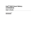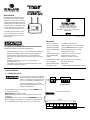
1
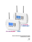
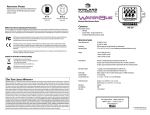
QUICK START GUIDE This guide provides basic setup instructions for the EnviroAlert EA800 and EA800-ip Critical Condition Monitoring System and associated sensors. Installers should refer to the Installation Manual (found online at www.winland.com) for complete instructions and specifications, and to become familiar with the many features provided by the EA800. The EA800 allows connection of up to 4 wired and 4 wireless sensors. 1950 Excel Drive • Mankato, MN 56001 USA (Tech Support 8:00am - 5:00pm Central) (800) 635-4269 • (507) 625-7231 P • (507) 387-2488 F www.winland.com To use the EA800-ip’s advanced features, set up an account at www.ea800ip.com. Since the EA800-ip utilizes a cloud computing architecture, no client software is required. D-011-0153 Rev F (02/2012) SPECIFICATIONS READ THE INSTALLATION/OWNER ’S MANUAL FOR COMPLETE INSTRUCTIONS. Installation/Owner’s Manual can be found online at www.winland.com • All power terminals must be connected to a Class 2 power limited circuit complying with National Electrical Code NFPA 70, Article 725. Where required, this equipment is to be isolated from the main supply by a limited power source as specified in EN60950. • Batteries shall not cause explosion or produce a fire hazard as a result of excessive charge or discharge. • Ensure all wiring for wired sensor connections is done before powering on or programming the EA800 console. • If the equipment is used in a manner not specified by the manufacturer, the protection provided by the equipment may be impaired. EA800 Console Input Voltage 11 to 26VDC @ ≤ 500mA current draw Wireless Sensor Input Voltage (EA-WMFS, EA-WTS, EA-WHS) 12VDC @ ≤ 100mA current draw via 2.1 mm barrel plug, center positive OR 2xAA Alkaline Batteries (1.5V Cell) EA800 Console Auxiliary Output Voltage Equivalent to DC Input Voltage used: 11 to 26VDC. (Maximum output current 0.5A). Environmental Operating Range (EA800, EA-WMFS, EA-WTS, EA-WHS) Temperature: 0°C to 50°C (32°F to 122°F). Not for installation inside coolers or freezers. Humidity: 5% to 95% RH, non-condensing. Ambient Environmental Quality Indoor use intended, non-corrosive environment. Relay Contact Ratings Max 30VDC @ 1 Amp, resistive EA800 Real-Time Clock Battery CR2032 (3V Cell) Ethernet (EA800-ip only) 10/100BASE-TX/FX; fully compliant to IEEE 802.3u standard INSTALLATION OVERVIEW 1. Installing Base Console Do not connect or disconnect power, sensor, or alarm wiring while power is applied. Connecting and disconnecting the EA800 base console with power connected may damage the base console or result in improper or unreliable operation. J5 J6 Power In AuxPower Out 1 Connection of unsuitable loads to this connection may damage the power supply and EA800 base console, or result in improper or unreliable operation. Using a terminal block adapter, connect power supply + and - leads to POWER IN (+) and (-) on J5. Observe proper polarity. EA800 Input Voltage: 11 to 26VDC at ≤ 500mA Note: The input voltage specification does not include requirements for loads connected to Aux Power Out. If Aux Power Out is to be used, connect + and - leads to AUX POWER OUT (+) and (-) on J5 using a terminal block adapter. When base console is powered, a 30-minute timer starts. The console will alarm after this timer expires unless one or more sensors are installed. 2 3 4 Wired Sensor Inputs VIEW OF CIRCUIT BOARD IN EA800 BASE CONSOLE Relay Outputs 1 2 NO COM NC NO COM NC J8 3 4 5 6 NO COM NC NO COM NC NO COM NC NO COM NC J9 7 8 Aux NO COM NC NO COM NC NO COM NC J10 2. Unlocking/Locking Base Console Press F1 to unlock base console. The default password is 0800. See Installation/Owner’s Manual to customize password. To enter password, press F3 (Next) to move the cursor one digit to the right. Use the arrow keys to change the numeric value to 0800, then press to enter. The base console is now unlocked. After completion of steps 3 - 5, press F1 to lock the base console, if desired. The base console locks automatically if no keys are pressed within 30 minutes. 3. Setting Date and Time To set time and date format: The defaults are 24-hour clock (military time) and mm/dd/yyyy format. To change to 12-hour clock or dd/mm/yyyy format if desired, go to MAIN MENU, select System, ; select Configuration, ; select Date Format or Time Format, ; then select the preferred configuration. Press F3 (OK) to set. To set time and date: go to MAIN MENU, select System, ; select Set Date or Set Time, ; follow menu prompts and use PREV and NEXT soft keys to select the desired values. Press F3 (OK) to set. the screen does not contain the number found on the sensor’s PC board, press F1 (Cancel) to continue the search process. Select the output relay to which the wireless sensor is to be assigned, then press . Continue the setup based upon the type of wireless sensor being added. Wireless Multi-Function Sensor (EA-WMFS) Wireless multi-function sensors provide a wireless transmitter for connection to a wired sensor. Select the type of sensor to be connected to the wireless multi-function sensor, then press . Assign a Common name or Custom name to the sensor, and continue to follow on-screen prompts to complete the setup. Note: Custom names are limited to 16 characters for all sensors. Note: The Wireless Multi-Function Sensor (EA-WMFS) supports the following sensor types: Blue Temperature Probe (TEMP-L-W and TEMP-L-S) Red Temperature Probe (TEMP-H-W and TEMP-H-S) White Temperature Probe (TEMP-UL-S) Supervised WaterBug® Sensor (W-S-S and W-UC-S) Contact Sensors (N.O. and N.C.) Note: Not for use with the HA-III+ or 4-20mA sensors. These sensors can only be configured as wired. Wireless Temperature Sensor (EA-WTS) Assign a Common name or Custom name to the sensor, and continue to follow on-screen prompts to complete the setup. Note: Custom names are limited to 16 characters for all sensors. Wireless Humidity Sensor (EA-WHS) Assign a Common name or Custom name to the sensor, and continue to follow on-screen prompts to complete the setup. Note: Custom names are limited to 16 characters for all sensors. Repeat setup for each additional wireless sensor. The steps will vary depending on the type of sensor being added. Verifying Signal Strength 4. Adding Sensors After temporarily mounting the wireless sensors in the desired location, verify the signal strength at the base console by pressing MENU , select Sensors, ; select Performance, ; then select the sensor to be checked, . It may take as long as 30 seconds to acquire the current signal strength. If No Data is displayed in place of bars, it indicates that recent signal strength information has not been received. If this persists for 1-2 minutes without displaying any performance bars, it is a strong indication that your sensor is placed out of range with the base console. If fewer than two bars are shown, it is recommended that the sensor be relocated to obtain a better signal. Refer to the instruction sheet included with the wireless sensor for details on ensuring optimum signal strength. Press MENU key, use arrow keys to select Sensors and press . Select Add New Sensor, . Follow procedure 4a if adding a hardwired sensor and procedure 4b if adding a wireless sensor. 4.a Adding Wired Sensors Select Wired, . Select the type of sensor being connected. You can opt to select from a list of Common names or create a Custom name (16 characters or less). After assigning a name, continue to follow the on-screen prompts to complete the programming of your sensor. See Installation/Owner’s Manual for details. Repeat setup for each additional hardwired sensor. The steps vary depending on the sensor type being added. Note: For detailed information on configuring a 4-20mA sensor, please refer to the Installation/Owner’s Manual. 4.b Adding Wireless Sensors Remove cover from wireless sensors until setup is complete. With the wireless sensor unmounted and located near the base console, apply power to the sensor using remote power supply or 2 AA batteries before starting setup. It is recommended that power is applied to one sensor at a time, and that the setup is completed for that sensor before adding subsequent wireless sensors. Select Wireless, press . The base console searches for a connection with the wireless sensor. This may take 1-2 minutes. Note: Press the Reset Button on the sensor to restart the search process if necessary. Verify that the number shown on the base console screen matches the number on the sensor’s PC board. Press . If the list of number(s) on Reset Button Sensor Model Number Example: EA-WTS = Wireless Temperature Sensor 5. Advanced Settings Refer to the Installation/Owner’s Manual found online at www.winland.com for configuring the following advanced EA800 settings: • Configuring the Relays • Pausing Monitoring and Cancelling Pause • Replacing a Sensor • Editing Sensor Parameters • Changing Sensor Data Collection Frequency • Changing the Buzzer Setting • Clearing the Alarm/Sensor Logs • Saving/Loading Configuration Settings • Exporting the Stored Logs