1
~-
<:::c::
==-~
AE5~cm~TM~
I
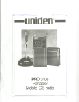
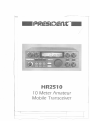
HR2510
10 Meter Amateur
Mobile Transceiver
:[
r
'---,
_.----
-
------
1
,
.Contents.
Welcome. . . . . . . . . . . . . . . . . . . . . . . . . . . . . . . . . . . . . . . . . . . . . . . . . . . . . . . . . . . . . . . . . . . . . 2
Controls and Functions
3, 4, 5
Front Panel Connector. . . . . . . . . . . . . . . . . . . . . . . . . . . . . . . . . . . . . . . . . . . . . . . . . . . . .. 6
Rear Panel Connectors. . . . . . . . . . . . . . . . . . . . . . . . . . . . . . . . . . . . . . . . . . . . . . . . . . " 7, 8
Installation. . . . . . . . . . . . . . . . . . . . . . . . . . . . . . . . . . . . . . . . . . . . . . . . . . . . . . . . . . . . . . . . .. 9
Operation. . . . . . . . . . . . . . . . . . . . . . . . . . . . . . . . . . . . . . . . . . . . . . . . .. 10, ", 12, '3, 14
Specifications. . . . . . . . . . . . . . . . . . . . . . . . . . . . . . . . . . . . . . . . . . . . . . . . . . . . . . . . . . . . . .. 15
Troubleshooting.
. . . . . . . . . . . . . . . . . . . . . . . . . . . . . . . . . . . . . . . . . . . . . . . . . . . . . . . . ..
16
Amateur Radio Operation. . . . . . . . . . . . . . . . . . . . . . . . . . . . . . . . . . . . . . . . . . . . .. 17, 18
'"
-
----
r-
1
,
'Welcome!
-
.
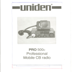
To the world of 10 Meter amateur radio communications! You have purchased
what we feel to be the finest 10Meter mobiletransceiveravailable.YourHR2510
has been designed using the latest state of the art electronics to give you years of
trouble free seNice. Toget the most fromyour HR251 0, please read this operating
guide thoroughly.
WARNING: You must have a 0.0. T.C.Amateur Radio Operator's License to legally transmit using your transceiver. Transmitting without a license carries heavy penalties.
Unpacking
Your HR2510 is supplied with the following items. Ifany items are missing or appear damaged, DO NOT return the unittothe place of purchase. Instead, contact
Uniden Australia Pty. Ltd. at your nearest dealer as shown on the back cover.
.
HR 2510 10 Meter Transceiver
.
.
.
Dynamic Microphone with Channel Up/Down control
.
Accessory Plug (Jumpered for internal speaker use)
.
.
Accessory Plug (With wires for connecting accessories)
Transceiver & Microphone Mounting Brackets & Hardware
Power Cord with In-Line fuse holder
This operating guide
We also recommend that you retain the original box and packing, as it makes a
convenient way to transport the unit.
2
-
r-
-------
-f
J
4-.
~
-
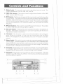
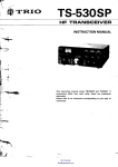
1. Mode Switch This control is used to select the desired transmit mode. The
modes available are: CW, LSB,USB,AM, and FM.
-
2. SWRjCAL Control This control is used to adjust the calibration of the SWR
meter while in SWRCAL mode.
3. RITControl- The Receiver Incremental Tuning control is used to fine tune the
received signal. This is used in USBand LSBmodes to obtain maximum clarityof
reception, and in CW mode to control the pitch of the beat note. The R/Tcontrol can tune the receive frequency about :t 3 KHz. This control will not aff~ct
the transmit frequency, or the frequency display, but will change the receive
frequency.
4. RF Gain Control- This is used to vary the RFinput to the receiver. This control
is used to help eliminate strong, adjacent signals.
-
5. Mic Gain Switch Pressing this switch activates the built-in microphone attenuator. This feature is designed to be used when operating the HR2510 in
high ambient noise environments.
-
6. TX Switch The TXswitch is used to lock the transmitter on for tuning purposes, except in CW mode. In CW mode the external key must be locked
down. The rT)icrophone is disconnected unless the PTT switch is also depressed.
7. Meter Switch - This switch is used to select the operating mode"for the multifuncion meter. The meter modes are: S/RF, Modulation, SWRCalibration setting, and SWR.Each time the Meter switch ispushed, the next mode isselected.
See the operation section for more information on meter usage. The currently
selected mode is displayed above the meter.
8. PA Switch
-Pressing this switch
enables the PA Mode, ifan external PA speak-
er is installed. When in PAmode, the normal transmit functions of the radio are
disabled, but the receive audio is routed through the PA speaker.
9. NB Switch
-Pressing
this switch enables the built in noise blanker.
The noise
blanker in your HR2510 isvery effective in eliminating interference generated
by vehicle ignition systems.
3
=t
1
--'--
=]------
~
-'<"-c>.-.
-'
'--"'":c--',.,--",,-',/
'
-
Controls and',Functions
-'continued
Scan Switch - The Scan control is used to scan up to 50 channels
10. Dim Switch Pressing the Dim switch dims the display backlighting. Press
again to return- back lighting to its normal (high) level.
11.
in each
band segment. See the section on operation for more information on using
the Scan Control.
12. Span Switch
- This control
is used to select either 10KHz, 1 KHz, or 100 Hz
steps for the VFO. The currently selected step is indicated by a line under the
relevant digit on the Frequency Display.
13. Channel /\ and V - Pressing these controls will step up or down to
the next 10KHzchannel in the currently selected band segment. The currently selected channel is displayed next to the frequency display.
-
14. Band Switch Pressing this control will select one of the four band segments. Band segments are: a:28.0000 - 28.4999, b:28.5000-28.9999,
c:29.0000-29.4999, and d:29.5000-29.6999 MHz. The currently sel,ected
band segment is displayed above the channel display.
15. F. Lock Switch - Pressing the Frequency Lock button will disable all frequency determining controls on the front panel, to prevent accidental changes of
frequency.
-
16. VFO Control The Variable Frequency Oscillator-control is used to select
the desired transmit and receive frequency. Tuning is continous throughout
the entire range of the HR 2510, with no need to select band segments.
-
17. Squelch Control The Squelch control is used to adjust the squelch function, which eliminates the "rushing" sound between transmissions. Turning
the squelch control CCW until it clicks enables the auto squelch, eliminating
the need to manually adjust the squelch.
18. On/Off/Volume Control
and to adjust the volume.
-This control is used to turn the unit on or off
-
19. Beep Switch Pressing this control will cause a short beep tone to be transmitted whenever you release the PTTswitch on the microphone.
4
----
~
r
-. --.,=--=
-
==-,.
Contro;! and functions - continued
-
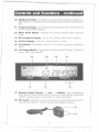
20. Multifuction Meter This meter can display S/RF, Modulation, SWRCal, or
SWR. See item (7), Meter Switch and the operation section for more information.
-
21. Frequency Display The Frequency Display displays the currently selected
transmit and receive frequency.
22. Meter Mode Display - Displays the currently selected meter operating
mode.
23. Band Segment
Display
- Shows
the currently selected band segment.
24. Channel Display - Gives the selected channel number.
-Illuminates when PTTor TXSwitch is pressed, or CW key is
VFO Step Indicator -Displays the currently selected VFO step. (The photo
shows 100Hz step selected).
25. TX Indicator
down.
26.
-
27. Remote Control Channel 1\ and V switches You can step up or
down by one 10KHz channel within the current band segment using these
controls. See the section on operation for more information.
28. PTTSwitch The Push to Talkswitch is used to control the transmit and receive of your HR 2510. Press to transmit, and release to receive.
-
,~
5
_.
1
r
~
-
.
.
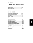
Front Panel Connector
0
4--
Transmit (PHI
0
Microphone
Connector
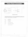
The microphone included with the HR2510 is a 500Q dynamic microphone, with
channel up and down switches. The view of the connector is facing the HR2510
front panel. The pin connections are as follows:
Pin
Connection
1&2
Microphone
3&2
PTTSwitch
4&2
Channel Up Switch
5&2
Channel Down Switch
2
Common Ground
6
~
---
-
r
1
h . ...r
_.
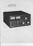
Rear Panel.Connectors
0
0
0
1
2
3
0
0
0
4
5
6
0
0
0
7
8
9
Accessory
Connector
There are two plugs forthe accessory connector included with your HR251 O. One
plug contains only ajumper between pins 1 and 7, which is used only to enable
the internal speaker. The other plug iswired so that you can convenientlyconnect
accessories to your HR 2510. The view of the connector is facing the rear panel of
the unit. The pin connections and wiring color codes are as follows:
Pin
Wire Color
Connection
1&2
Red/Black
External Speaker
4&5
Blue/Black
PA Speaker
8&9
Black/Yellow
CW Key
1&7
Red/Wh ite
Internal Speaker (Jumper to use internal
speaker, open if external speaker is connected.)
3&6
n.c.
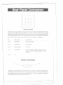
Power Connector
-
1001'
+
The power cord included with the HR2510 is color coded. The red wire goes to +
13.8V DC nominal and the black wire goes to ground. The HR25 J0 is designed
for operation with a negative ground system only. The view of the power connector is facing the rear panel of the HR 2510.
7
-------
r----- ~
~
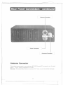
Rear Panel Connectors - continued
Antenna
Power
Connector
Connector
Accessory
Antenna
Connector
Connedor
The antenna connects to an ordinary 50-239 Female RF connector on the rear
panel. The RF output impedance is 50Q.
Warning: Standing Wave Ratios in excess of 2: 1 may cause transmitter damage.
8
y::::
r
1
--~=
'Installation.
Transceiver Mounting
Plan the location of the transceiver and microphone bracket before starting the installation. Select a location that is convenient for operation and does not interfere
with the driver or passenger in the vehicle. The radio should be secured to a solid
surface, using the mounting bracket and self-tapping screws supplied.
Mobile Antenna
The antenna is a very important factor affecting transmission and reception. It is
for this reason that we ~trQnglyrecommend that you install only a quality antenna
in your new HR 2510 system. You have purchased a superior quality transceiver;
don't diminish its performance by installing an inferior antenna.
Only a properly matched antenna system will allow maximum power transfer from
the 50Q transmission line to the radiating element. YourUniden dealer is qualified
to assist you in the selection of the proper antenna to meet your application requirements.
For automobile installations, a quarter wave whip antenna may be used with
good effect. The most efficient and practical installation is to mount it on the rear
deck or fender top midway between the rear window and bumper.
A short base loaded whip antenna is more convenient to install, but the efficiency
is less than a quarter wave whip.
For marine installations, consult your dealer for information regarding an adequate grounding system and prevention of electrolysis.
Warning: Standing Wave Ratios in excess of 2: 1may cause transmitter damage.
Ground
Information
Most newer and foreign made cars and small trucks use a 13.8 V DC nominal negative ground system, while some older cars and large trucks use a positive ground
system. A negative ground system is generally identified by the negative (-) batteryterminal being connected to the vehicle frame or engine block, but ifyou cannot determine the polarity ofyour vehicle or are unsure, contact your vehicle dealer for definite information.
Warning: Your HR 2510 is designed for operation on a 13.8 V DC nomina/, negative
ground system only. Operation on other vo/tages orpo/arities may cause fires, transceiver damage, and/or other hazards.
Power
Cord Connection
The red lead (with the inline fuse) of the supplied power cord is to be connected to
a "hot" (positive) wire, and the black lead to ground. As the HR2510 draws appreciable current during transmitting, you may wish to connect the positive lead
direcly to the battery, or to a main supply wire.
9
--
r
-----
f
J
Operation
Selecting a frequency
VFO Operation
Selecting an operating frequency using the HR2510's built-in VFO is easy. Make
sure that the F. Lock key is NOT depressed, and then simply rotate the dial to the
desired operating frequency. The VFO will step in either 10KHz, 1 KHz,or 100 Hz
increments. The step increment is indicated by a line under one of the 3 rightmost
digits of the frequency display. To change the VFO step, press the Span button
until the desired step is indicated by the black line. When using the VFO, you do
not need to manually select the band segment, as this is done automatically, so
that the tuning range is continous throughout the entire operating frequency
range.
Channel Select Operation
You may also select the operating frequency using the Channel 1\ and V buttons on the front panel or the microphone. The channel select buttons will select
any 10KHz channel in a band segment (50 channels in a; 28.0000 to
28.4900,b;28.5000 to 28.9900, c;29.0000 to 29.4900, and 20 channels in
d;29.5000 to 29.6900 MHz). The 10KHz channel frequencies are pre-programmed and cannot be changed. When stepping up or down, the unit will tune
to the nearest 10KHz channel. NOT to the dial frequency + or - 10KHz. When
you reach channel 50 (channel 20 in segment d), pressing the Channel 1\ button again will step to channel 1, conversely, when you are on channel 1, pressing
the Channel V button will step to channel 50 (channel 20 in segment d).
Toselect a band segment, press the Band button until the desired band segment
letter is displayed. It is displayed on the display above the channel number.
Ifyou press and hold down the Channel 1\ button, the HR2510 will continuously step up through the pre-programmed channels. As it reaches channel 50,
(channel 20 in segment d), it will go to channel 1, stop momentarily, and beep to
let you know that you are at channel 1. In the same manner, pressing the Channel V key wil also do this, but it will stop and beep at channel 50 (channel 20 in
segment d) to let you know.
10
"f::
-
L
------
-'-==
I
Operatigrl..continued
-
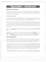
Receive Scanning
The receive scanning functions of your HR 2510 make it easy to find active frequencies. Youcan scan 50 10KHz channels in segment a,b,or C.and 20 channels
in segment d. Scanning is always from the lower frequency to higher frequencies,
and always in 10KHz steps.
Scanning Operation
To begin scanning, press the Scan button. Ifthere isa transmission on the current
frequency (the squelch is broken open). pressing the Scan button willjust step up
one channel. If the squelch is NOT broken, scanning will begin.
The unit will scan through the selected band segment until it encounters a signal
strong enough to break (open) the squelch. It will then stop on that frequency for
the duration of the transmission. When the transmission stops, the HR2510 will
wait approximately 1.5 seconds before resuming the scan cycle, to allow you to
hear a return transmission on that channel. Ifyou take no further action, the scan
will resume.
When the scan has stopped for a transmission, momentarily pressing the Channel /\ or Channel V switch on the microphone will stop the scan on the
channel.
To exit from scan mode while still scanning, simply press the Channel /\ or
Channel V button. If the scan has stopped on an active frequency, you can
press the Channel /\ and V buttons on the microphone, orthe Channel /\
and V " F. Lock, Band, or TX buttons on the front panel of the HR 2510.
CW Operation
Using CW mode with the HR2510 is easy. Just select your operating frequency,
place the mode switch in CW, and you're ready to transmit CW ifyou have connected an external key to the accessory plug on the rear of the unit. (See the section on rear panel connectors for informationon connecting a CW key.)
To use CW mode with an external key, select an operating frequency, place the
mode switch in CW, and you are now ready to operate as semi break-in CW mode.
(Ifyou leave the key up for more than 1 second, the receiver is enabled. The HR
2510 has a built-in sidetone oscillator foryour convenience. Note: Ifthe TXswitch
is depressed, the receiver will be disabled. The HR2510 will NOT transmit in CW
mode unless an external key is connected and in a key down condition.
To adjust the pitch of the received CW note, you can use either the VFO or RITto
tune it as desired. (Note: Adjusting the RITwill NOT affect the frequency display)
11
--
--------
Ii
I
~
_.
Operation -con'inued
USB/LSB/AM/FM Operation
Using the HR2S 10 for voice communications as either USB,LSB,AM or FMmodes
is simple. Simplyselect your desired operating frequency, turn the mode switch to
the desired type of operation, and the P1T switch controls the transmit and receive. To fine tune the receive signal in USBor LSB,you can use either the VFO or
RITcontrols. (Note: Using the RITcontrol to fine tune the receive frequency will
NOT affect the frequency display.)
The Mic Gain control can (and should) be used when you are transmitting from a
high ambient noise environment. Pressing the Mic Gain control reduces the output from the microphone. Press the Mic Gain control again to restore it to normal
operating condition.
Noise Blanker
The noise blanker has been designed specificallyto remove the interference generated by vehicle ignition systems. To use the noise blanker, simply press the NB
switch. To disable the noise blanker, just press the NB switch again.
F. Lock
The Frequency Lock function is used to lock the frequency determining controls
against accidental changes. To lock the frequency controls, press the F. Lock button. To unlock the frequency controls, press F. Lock again.
Beep Control
The Beep control enables and disables a short "beep" tone that is transmitted
whenever you release the PTTswitch (except in CW mode). This is especially useful when transmitting is USBor LSBmode, as it lets the station that you are working know that you have stopped transmitting. Press the Beep button to enable
the beep tone, and press it again to disable it.
12
-
--
-
r
1
Operation> -continued
Multifundion
Meter
The Multifunction Meter built in to your HR 2510 provides a number of useful
functions. These are:
. SjRF Meter
. MOD Meter
. SWR CAL Meter
. SWRMeter
Everytime you press the Meter button, the next function will be selected. When
you reach the end of the functions, it will start over with the first.
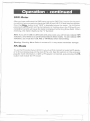
S/RF Meter
The SjRF meter function provides a visual indication of relative received signal
strength and relative transmit power. To use the SjRF function, press the Meter
button until "RF" is displayed over the meter display. The meter automatically
switches function depending on whether you are transmitting (RFMode) or receiving (S mode). When receiving, the meter reverts to the "S" function.
MOD Meter
This function gives you an indication of the strength of your modulation when
transmitting. There is no function for this meter when receiving signal~. To use
the MOD function, press the Meter button until "MOD" is displayed over the meter display. When receiving, the meter reverts to the "S" function.
SWR CAL Meter
This mode of the multifunction meter is used to calibrate the meter for the SWR
function. To use this mode, first place the unit in CW, AM, or FM modes. Then,
press the Meter button until the small triangle is visible under the meter near the
right side. No other mode indications will be visible at the same time. Press the
PTT switch on the microphone or hold down the CW key (ifconnected), and adjust the meter using the SWR CALcontrol until it indicates up to the triangle.
When you have done this, you are ready to check the SWRusing the procedure under "SWRMeter". When receiving,the meter reverts to the "S" function.
Note: Don't forget that a/ltransmissions must be properly identified, and remember
to listen on the frequency before transmitting.
13
q::
--
---- r-
--==-=--.,..
F-=
(
Qperation
-.continued
SWR Meter
Afteryou have calibrated the SWRmeter using the SWRCALfunction (in the previous section' you are ready to check the SWRof your HR251 0 and antenna system.
Press the Meter button until "SWR"is displayed above the meter. At this point,
pressing the PTTswitch on the microphone, or holding down the CW key (ifconnected) to transmit will cause the meterto display the Standing Wave Ratio. When
receiving, the meter reverts to the "S" function.
Note: If you are in USB or LSB modes and using voice, you will not see a steady S WR
indication, since there is no carrier transmitted in these modes. To see a steady SWR
indication, you must be in C~ AM, or FM Modes when transmitting.
Warning: Standing Wave Ratios in excess of 2: 1 may cause transmitter damage.
PA Mode
To use the PA mode of your HR251 0, you must first connect an external PAspeaker to the accessory plug on the rear of the unit. (See the section on the accessory
plug for more information.' With a PA speaker connected, just pressing the PA
button will enable the PA mode.
14
r
-,-,,--
""-
-
r
. Specifications'
General
Frequency Range
Microphone
Band A
Band B
Band C
Band 0
500Q Dynamic.
/\&V
Speaker
Operating Modes
Display
Display Items
Size
Weight
28.0000-28.4999 MHz
28.5000-28.9999 MHz
29.0000-29.4999 MHz
29.5000-29.6999 MHz
w/PTT and Channel
8Q,3W
CW, USB, LSB,AM, FM
Backlit LCD
Frequency, Channel # ,Meter, Meter Mode,
TX,Band, VFO Span
7.32" x 10.35" x 2.44"
4 Ibs 3 oz
Transmitter
Frequency Stability
Output Power
Spurious Harmonic Emissions
Carrier Suppression
Unwanted Sideband
Suppression
Power Consumption
(No Modulation,
PTT Depressed)
(Max Modulation)
Microphone Input
CW Key Voltage/Current
:t 300 Hz Nominal, (@25°C, 5 Minutes after
Power on)
CW 25 W Nominal
USB/LSB25W PEP Nominal
AM/FM IOW Nominal
-50dB Nominal, all modes
-55 dB Nominal, USB/LSBModes
-45 dB Nominal, USB/LSBModes
AM/FM 3A Nominal
USB/LSBO.8A Nominal
CW SA Nominal (Key Down)
AM/FM/USB/LSB 3A Nominal
1 mV Nominal for 50% AM Modulation
8V DC, 10 mA
Receiver
AM .5J1VNominal
CW/USB/LSB .25J1VNominal
Sensitivity for 20 dB SIN
FM .5J1VNominal
Adjacent Channel Selectivity
70dB Nominal (10KHz Spacing)
Max. Audio Output
4W Nominal
RF Gain Range
55 dB Nominal
RITRange
:t 3KHz Nominal
"s" Meter Sensitivity @S9
100J1VNominal
Image Rejection Ratio
65 dB Nominal
Power Consumption, No Signal 500 mA Nominal
Power Consumption, Max Audio 1000 mA Nominal
Sensitivity for 10 dB SIN
15
"-
--
r
f-
------
Troubleshooting
Ifyour HR2510 ;s not performing up to your expectations, please try these simple
steps. Ifyou still cannot get satisfactory results after reading this manual and following the troubleshooting steps, please contact your dealer.
Trouble
Check
Unit will not turn on
1. Check power cord and all connections.
No Power
2. Check power cord fuse.
3. Check vehicle electrical system.
4. Check unit grounding.
Poor Reception
1. Check & adjust squelch.
2. Check antenna.
3. Check antenna cable.
4. Check antenna connectors.
Weak Transmission
5. Check operating mode of radio.
1. Check antenna.
2. Check antenna cable.
3. Check antenna connectors.
4. Check operating mode of radio.
5. Check antenna SWR.
6. Check antenna grounding.
7. Check for corrosion on connectors.
16
r::::
-----
r
j
,
-"~~
~<-
~
<
,-
-<
r
We designed your HR2510 transceiver to be the perfect first radio for anyone entering the exciting world of amateur radio. From your home, car, or boat, you will
find that your transceiver opens a door to the world - literallylAllyou need is a
source of electricity, a suitable antenna, and, most important of all, an Amateur
Radio Operator's License issued by the Department of Transport and Communications (0.0. T.C).
Possiplyyou are already a licensed operator. In fact, you may have been an amateur radio operator for some time. But, ifyou do not have a license, you wW discover that it is easy to get one, and that there is help available. Here are a few tips
to help you get started.
First, go ahead and connect your transceiver as described in the "Installation" section of this manual. Use the receiver to tune around on the band to see what is going on. Do not even think of transmitting ...ntll you get your license! This is
extremely important. Transmitting without a license is breaking the law and can
lead to severe penalties. Also amateur radio operators take their hobby very seriously and want nothing to do with "pirates" their term for people who operate
without a license.
-
Second, find out if there is an amateur radio club in your area. There are many
clubs around the country, so there is probably at least one in or near your own
community. The people at the store where you bought your equipment might be
able to tell you. If not, and you do not hear anyone talking about a local club in
your area as you tune<around the band with your receiver, write to the Wireless Institute of Australia (WIA)for information on how to contact a local club. Most
clubs welcome newcomers and are glad to give advice on how to get your license.
Next, start studying for your licence. Do not let the word study scare you, because
most people can go from knowing absolutely nothing about amateur radio to
passing the basic (Novice) class licence examination in approximately six months.
The examination tests your knowledge of basic radio regulations, elementary radio theory, and slow speed (5 words per minute) morse code. Some clubs teach licence classes (a fun and easy way to learn about amateur radio), and there are good
books, cassette tapes, and many other study aids available.
17
--
r
------- 1
I
- -
-.
-.
AmateurR~dioOpera~ion-contin_u~d
The Novice Class licence allows you to use your HR25 J0 transceiver between 28. J
MHz and 28.6 MHz. You can transmit CW (Morse Code) on your allocated frequencies, but you are only permitted to transmit voice on the Ja-meter band frequencies from 28.3 MHz to 28.6 MHz.Your HR25 J0 can tune up to 29.6999 MHz,
but these higher frequencies are reseNed for the advanced licencees. Keep on
practising and learning, and soon you will have legal access to all the frequencies
accessible with your transceiver.
Eventually, you will want to get a higher class of amateur licence, with more privileges. Examinations for Full call, Limited and Novice licences are conducted approximately every three months at present by the Department of Transport and
Communications in your Capital City and some provincial centres.
We have mentioned the W/Apreviously. They are the national organisation which
represents the amateur radio operators in Australia. The W/A has approximately
8,000 members; most of them radio amateurs, but some are short wave listeners.
Here is the address of the W/A Executive office.
Wireless Institute of Australia
P.O. Box 300
South Cau/field
Victoria 3 J62
Telephone (03) 528 5962
The W/A staff helped us prepare this section of the owner's manual. Ifyou need
more information, or you would like to join the W/A please phone or write.
Amateur radio isa great hobby that has enriched the livesof millions of people the
world over. Tandytakes pride in bringing to you the HR25 J0 transceiver which no
doubt will bring you many hours of enjoyment.
J8
-.- --
~
r
--=
~
Warranty
WARRANTOR: UNIDEN Australia Pty. Ltd. ("UN/DEN".)
ELEMENTSOF WARRANTY: UNIDEN warrants to the original retail owner for
the duration of this warranty, UNIDEN CS Product (hereinafter referred to as the
Product) to be free from defects in materials and craftsmanship with only the limitations or exclusions set out below.
WARRANTY DURATION: Thiswarranty to the original user shall terminate and
be of no further effect One (1) Year after the date of original retail sale. The warranty is invalid if the Product is (A)damaged or not maintained as reasonable or
necessary, (S)modified, altered, or used as a part of any conversion kits, subassemblies, or any configurations not sold by UN/DEN. (e) improperly installed, (D) repaired by someone other than an authorized seNice center for a defect or malfunction covered by this warranty, (E)used in any conjunction with equipment or
parts or as part of any system not manufactured by UNIDEN (F) installed, programmed or seNiced by anyone other than an authorized UNIDEN seNice center.
STATEMENTOF REMEDY:In the event that the product does not conform to
this warranty at any time while this warranty is in effect warrantor will repair the
defect and return it to you without charge for parts, seNice, or any other cost incurred by warrantor or its representatives in connection with the performance of
this warranty. THISWARRANTYDOES NOT COVER OR PROVIDE FOR THE
REIMBURSEMENTOR PAYMENTOF INCIDENTAL OR CONSEOUENT/AL DAMAGES.Some states do not allow this exclusion or limitation of incidental or consequential damages so the above limitation or exclusion may not apply to you.
PROCEDURE FOR OBTAINING PERFORMANCE OF WARRANTY: In the
event that the Product does not conform to this warranty, the Product should be
shipped or delivered, freight prepaid, to warrantor at 345 Princes Highway, Rockdale, NSW. 2216 with evidence of original purchase.
LEGALREMEDIES:Thiswarranty givesyou specific legal rights, and you mayalso have other rights which vary from state to state.
19
""
--
~
r
:=;::J«;",;:.".-i:j~,
1
r
.~!!-I-n -~:o-
~
'"
m "n'n'~r"O"--:
'::'
' '~~ '11; :'~"'!ii
~~
~ ~ !l
=
.,'""" ."',''J",'
I
'
'
l
1
"'-"
:.>-<
-,.
'
,
'~
"'.'" c":.."
..
'..
".,
".",. ",
,..
., "'" '"
""
I 1':1,1<10
,
! I'~r;,~,r;~'::l;""'-;"I
,."
12IT
'! ~:'-=
I
1
.;~
'
"b~
1~.I..
",
; 1"'"
[!
"--.1 0;..,
l'
:1;!
.
"
- - ,""
:~,.
Vr~r~lt"
~"1
'=:.",,'
i.
"~O
::.'.",
'
~
I
~
i
1
I
~
-"+~p 1 .." .
'1
i
'
".,
,..".
.
.
~~
1~;',,~,
'I ,,~. ".:.
0
'"
.
i
,
~':::2:'::J,
"
-.l.'H:
.
I
1
~~---,1
. ,..i~o-:!I.,
"""',,"
~
~
I-.~~,..".
~' :~
11
lift
~~
~~
,
[;1
i
r
t :~
~
-~
I
-
;;:
"..
1.
!~ 1
."
I~
'1
~
..
~~1
....
"..
."
i
=-==<
".. ,,71
.""
","
"i;,(
;;;:d
-'1
[
"I
;;: 1
'-'"
J,
~..
~_.
~..," :i
~
;" .:. +:-~ ,i
,~ri,,": ~,
'>-<;;1"1
J~ l' ---,
::,
F:l~-5
'-1-.
. ?if..;-:.c~
~
~;
,
-"
~ ~:;"
'~'""
I
~
f ~i ';;~::.1;. ~ ...
. ~--£'
.
"'"
i
". O" ~~
~_-_n
n
;;:0
i
g~
,. :,
""
:~..
r
~~
,
"
,,-"~" ".
"., !~~
i
1I
:0
, ~j..
b'~.',Ir
"";: ",.,
" "'..
~i..
, cro",
~
- .".
> 0'-
,
1
.,..
jL
,,'
~ ~ ni~ ~~
~.,
, "" ,."i". '" ,. ;,..,
I
1. ",1*" I~"
~~
'~:,
~"
,
~;~:.:;;
;;:;;;m~~l
e-
'~:'J,=:
1'=')/:'",
~'~:.;:"
,I, '~
-..
~
-
i'
on
,""" - ]" ,
)~:. ,m ..".. i
~
.1,., ""w
I
1-
.
~':,:l
=~ ~;;;, ;:'
~
"..
'" !f¥..". rJ;;'-i
,~, - -
';:~,
i' '7:::::':~~.J.
""'.
". ..
-
'"
"'"'=
I~i
. . ..",
-",;::.~
',
,
~.". ':nj.'
":'". '
""
"'-
-J~
:
~
:
IT
:
~:
"~
r.~
~;~i
.. '"
J. .""
",.
: . ~~;,~
m ~~"t- ---- ;-' .
'
,- m "'.,
... J
'01 . ~. .
-=
",
' ,,":.
... .".--J~1
11
I
""',,'
i
r
.
'J'
-',
I
'::::l-"
~~ T
h,p.
%Ji, ""-:.,,, .>T, ~-:,:",::-';;
':; 1~~:-':" :':
, IT~:,"
~
'I =::,
.
. ..
~ --t-:c:c
,+1-1
,
,i~~
"" ',="
,."
-;00,;
~ ~..'"
~
1
i
~;
.-~:
"
..,
0
~
i
" ...
c-'o
, .. . .
..:
-- ~""
,-
,..
,I
'"."
a;;;
'
:...~ ,""
1
.
l
!-,.
:_--~.1
~
~
',.,
:
;
I
w.".
..
1
,
-;',
i
:
i§~ 1
I
,;:..; "
I '!1 :;:~~ i~ :::.
-"L"
-;;;-..J :';.}~ .( ""'-6
.'".b~
;~
1 .~ '..
~" ;:!
-:::'!;- '",.~:. .:I'III~~lk:J-j::'".
i 'f::-'"
~ I~'1 I
1
I
.
"
le",.., '.1 ~',".'
~,"'.
,..~~';,~
"~
'=" I
~
:<;
'- ,,'" .,g~'h'"
~.
",
.
;;:
~
.
:
""w
,.
""'.. '.,I
>
.. ,"I
"", ~, ,.
,>-"'-"'-
,
~
I
I
~
i~
I~
t3:jfr-l---
~
11
",
~I;'
.
.
t~:
i
;,
,~".!
.~
"no i;
..'. "., --
,. ,
~
,. Jf8jj;~
,------;;-'"'.;,:
'm",__- .
,,"".:;::,
p.-,"~-~
..
. -+1,
i,~
i
::::-"" ...", ;EI
.1..~. g;
! I;:
'"
i,
~;~:
i
(
~
1
~nm
.
:
'ir tQ~ :~:.{~
:"
~:':, ,~~,:.t \ "
~/..
I"m,*,~,
,1 " J
~~ ;'::
.:;~. _n- ";
~
i ,,""
>-~ ~;; ,~;,
I ';<.",' hit...I" i'iI" .~" '." : :: i';~
: " >---+:::- , """', "'L_~..
'--",=
'"
: .,' : '.."
" ~DIf~
:!i. I I; I ~~'
I '
i
,,-'..
_
:
:;;
~;~~E~~. i
II~!-~':'0
ij!!n~
..I[ ~g
. """ .:::"
,L
.. "." ':;. ~ """-;".
., ",: 'i ,
. .!:-""i:, ,'ii--r'
,,~,
"",
~"
,iJ
=::::'..J'
I1;;J ~""
~-=~:;
:::~; :I~.
~r
m~~~;~'I~
1
'::"
IT' ;,'
,. !i1-"
!1~::ili .,'
~ r-:
r.=-:t:'.~
F h .,n' ..1"
.."
r--,j~ii ~
~,:.
-;~-",[§lJr
= ;1:r ;'J ,
lt ~~I;1,cJ'U
IJ
+ l fT" 1 YG"
W'. .
...
,.
+.
[[+
~~"
. l='..- ..
:
"
I
!
I' ""'~~:'
..,...~~
-
~
1
~§~:<:
~K~~~ ~~§:
,
~L~
~
'
:-
~
, ::
Ir;Y
1'1;
~,1
1
'.
~
L-'--
-
-.
-~.
rftf
'.
I
111
i~
i
l
U
m
"
11'"
Jil~
r~
~-
0
,: 'F~h
-
1
I
1
.
~ 'i
~
~
1
:<;~
~fi1
I
11
ID -!!. 1+
li
~
!~
~l 1:-:::
~
.
TTr,; - ~ I;;" .' I"", '. i!: :If'j +==
"I "',,:. mn,'
1 -~ ~ I';::::
~, =1 - ~."
F}L,o"
~'I
1 .~,
, -,.
0
,> - I.
'.
": II
H :1~j~~: :: - -- _:~J
';1I
~l~
u"
~
~Ii~'dl
~~
'f:1
~~-»i
G "
.. ~ ~
~.I I1
,,~ :J} ~..,'7.;
'1'
~;.:,~.:miitt UI~~
C'="'-~'~
I
.;,
1
l
~;~/I
;l :r)J
"f]',
~~~~~
.
0
I
:::
11
.
"
,
~~.
;
::
','ffffn
~
~~.,_.
"-"
,~
i
I
H:
"",,, - :,
;. . ~;;:ot
;:;:=
~::;j,
~
i
..
"
':~m_n::0
=~
n
i
1
:
J:
~
20
r=:::
------ ~
~
1
(
i-_u
uu
:
!
I
:
I
N'
I
I
..,
w.
I
I
:
.:
;
..
.
.n
;"
,n
§
yf:
,,
,I
1
I
I
,~
~ .
~
<Un
~ ::
.',
.M
..,
.',
.'.
:::
:i
'~I
5
j 9
iI.. ~
::~
~ ~
'~.'"
"..
i;:
::: -,
~~
.
,I
~n
;.;:'
li!,!llil!,I,!
I :-:::::::~:::::f--'
ii-!
§ :. ~n..
un.~.n..
II
I
ii
:~:
,'I
"I
~
i
,=
,,'"
~u_=====~~~~~~~~~_l::::::=::::l!
,
I
I
.
r. L~?
:«" n ~~~. "'1f=-=*
;~~
:
:
~~~
U-1
1
m
I
I
I
I
I
I
I
I
I
I
h_nu
-tl
i"i~~~~~!~~~~;~;;~
,
~;n
1,---[
i!
I:
'I
"
,I
,,
,,
,,
,,
,,
,,
I
I 4
L'
~
';:,
,
I
I
I
~
,,
,,
I
:;00;;..
,."',',,.
",',;..
IM"',;..
IM'....
IM'-M"
IM'-"..
: 5""..
:! ';
i
-
I
I
I
I
I
,,
,I
I
I
I
:
..".. ",,-,
i
." ,'"
M'-CU'
"""'
~
""'"
I
.-,;,,:I
I
§
j~~
I
." M"I11
1
M"'"
M'
M'm.
M' n"
--
di_
I
:;;
~
!
I:
I
I
ll
,,
,,
,,
I,
,,
,,
r- ~';,!~
GEl
~HMn-~~CI
;;~
~:'T~
~
----
f
---
1
u~tj
-
__nn_§~t-i~_nnn
n_~;
~~~
21
-
I,
,I
I
I
I
I
rr.~
~~---
I
1
,
2!
n
1
I
,
'! !
6u
,
M."'..II,
"0
!I~I'I!I
I
II
I
M' " ,
M'"" ,
-
--
------
r
_h___-
r
uniden@
Australia Pty. Ltd.
HEAD OFFICE:
345 Princes Highway, Rockda/e, NSW.
Phone: 599 3355
Fax: /02) 5997657
2216
BRISBANE
3/12 Randall Street, Slacks Creek,
Old. 4127
Phone (07) 290-1188
Fax (07) 808 425 I
PERTH
MELBOURNE & TASMANIA
446-448 Bell Street, East Preston,
VIe. 3072
Phone (03) 484-0373
Fax (03) 484 6057
ADELAIDE
72-74 Halifax Street, Adelaide
SA 5000
Phone (08) 223-4235
Fax (08) 223 1471
23 Geddes Street, Balcatta,
W.A. 6021
Phone (09) 344-3937
Fax (09) 349 8165
UTUAO I 550DZ
Printed in the Philippines
'F:::
-
----
r
f
J