1
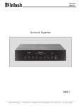
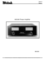
Owners Manual MC202 Power Amplifier MC202 McIntosh Laboratory, Inc. 2 Chambers Street Binghamton, New York 13903-2699 Phone: 607-723-3512 FAX: 607-724-0549 The lightning flash with arrowhead, within an equilateral triangle, is intended to alert the user to the presence of uninsulated dangerous voltage within the products enclosure that may be of sufficient magnitude to constitute a risk of electric shock to persons. WARNING - TO REDUCE RISK OF FIRE OR ELECTRICAL SHOCK, DO NOT EXPOSE THIS EQUIPMENT TO RAIN OR MOISTURE. IMPORTANT SAFETY INSTRUCTIONS! PLEASE READ THEM BEFORE OPERATING THIS EQUIPMENT. General: 1. Read these instructions. 2. Keep these instructions. 3. Heed all warnings. 4. Follow all instructions. 5. Warning: To reduce risk of fire or electrical shock, do not expose this equipment to rain or moisture. This unit is capable of producing high sound pressure levels. Continued exposure to high sound pressure levels can cause permanent hearing impairment or loss. User caution is advised and ear protection is recommended when playing at high volumes. 6. Caution: to prevent electrical shock do not use this (polarized) plug with an extension cord, receptacle or other outlet unless the blades can be fully inserted to prevent blade exposure. Attention: pour pevenir les chocs elecriques pas utiliser cette fiche polarisee avec un prolongateur, une prise de courant ou un autre sortie de courant, sauf si les lames peuvent etre inserees afond ans en laisser aucune partie a decouvert. 7. Unplug this equipment during lightning storms or when unused for long periods of time. 8. Only use attachments/accessories specified by the manufacturer. 2 The exclamation point within an equilateral triangle is intended to alert the user to the presence of important operating and maintenance (servicing) instructions in the literature accompanying the appliance. NO USER-SERVICEABLE PARTS INSIDE. REFER SERVICING TO QUALIFIED PERSONNEL. To prevent the risk of electric shock, do not remove cover or back. No user serviceable parts inside. Installation: 9. The equipment shall be installed near the AC Socket Outlet and the disconnect device shall be easily accessible. 10. Do not block any ventilation openings. Install in accordance with the manufacturers instructions. 11. Do not install near any heat sources such as radiators, heat registers, stoves, or other equipment (including amplifiers) that produce heat. 12. Do not use this equipment near water. 13. Do not expose this equipment to dripping or splashing and ensure that no objects filled with liquids, such as vases, are placed on the equipment. 14. Use only with the cart, stand, tripod, bracket, or table specified by the manufacturer, or sold with the equipment. When a cart is used, use caution when moving the cart/equipment combination to avoid injury from tip-over. Connection: 15. Connect this equipment only to the type of AC power source as marked on the unit. 16. Protect the power cord from being walked on or pinched particularly at plugs, convenience receptacles, and the point where they exit from the equipment. 17. Do not defeat the safety purpose of the polarized or grounding-type plug. A polarized plug has two blades with one wider than the other. A grounding type plug has two blades and a third grounding prong. The wide blade or the third prong are provided for your safety. If the provided plug does not fit into your outlet, consult an electrician for replacement of the obsolete outlet. 18. Do not overload wall outlets, extension cords or integral convenience receptacles as this can result in a risk of fire or electric shock. 19. To completely disconnect this equipment from the AC Mains, disconnect the power supply cord plug from the AC receptacle. Care of Equipment: 20. Clean only with a dry cloth. 21. Do not permit objects or liquids of any kind to be pushed, spilled and/or fall into the equipment through enclosure openings. 22. Unplug the power cord from the AC power outlet when left unused for a long period of time. Repair of Equipment: 23. Refer all servicing to qualified service personnel. Servicing is required when the equipment has been damaged in any way, such as power-supply cord or plug is damaged, liquid has been spilled or objects have fallen into the equipment, the equipment has been exposed to rain or moisture, does not operate normally, or has been dropped. 24. Do not attempt to service beyond that described in the operating instructions. All other service should be referred to qualified service personnel. 25. When replacement parts are required, be sure the service technician has used replacement parts specified by McIntosh or have the same characteristics as the original part. Unauthorized substitutions may result in fire, electric shock, or other hazards. 26. Upon completion of any service or repairs to this product, ask the service technician to perform safety checks to determine that the product is in proper operating condition. Thank You Your decision to own this McIntosh MC202 Power Amplifier ranks you at the very top among discriminating music listeners. You now have The Best. The McIntosh dedication to Quality, is assurance that you will receive many years of musical enjoyment from this unit. Please take a short time to read the information in this manual. We want you to be as familiar as possible with all the features and functions of your new McIntosh. Please Take A Moment The serial number, purchase date and McIntosh dealer name are important to you for possible insurance claim or future service. The spaces below have been provided for you to record that information: Serial Number: Purchase Date: Dealer Name: Technical Assistance If at any time you have questions about your McIntosh product, contact your McIntosh dealer who is familiar with your McIntosh equipment and any other brands that may be part of your system. If you or your dealer wish additional help concerning a suspected problem, you can receive technical assistance for all McIntosh products at: McIntosh Laboratory, Inc. 2 Chambers Street Binghamton, New York 13903 Phone: 607-723-1545 Fax: 607-723-3636 Customer Service If it is determined that your McIntosh product is in need of repair, you can return it to your dealer. You can also return it to the McIntosh Laboratory Service Department. For assistance on factory repair return procedure, contact the McIntosh Service Department at: McIntosh Laboratory, Inc. 2 Chambers Street Binghamton, New York 13903 Phone: 607-723-3515 Fax: 607-723-1917 Copyright 2000 ã by McIntosh Laboratory, Inc. 3 Introduction and Performance Features Table of Contents Introduction Safety Instructions ............................................................ 2 Thank You and Please Take a Moment............................. 3 Technical Assistance and Customer Service .................... 3 Table of Contents and General Notes ............................... 4 Introduction ...................................................................... 4 Performance Features ....................................................... 4 Dimensions ....................................................................... 5 Installation ........................................................................ 6 Rear Panel Connections and Switch ................................. 7 How to Connect for Stereo ............................................... 8 How to Connect for Mono .............................................. 10 Front Panel Displays and Controls ................................. 12 How to Operate ............................................................... 13 Technical Description ..................................................... 14 Notes ............................................................................... 17 Specifications ................................................................. 18 Packing Instruction ......................................................... 19 Now you can take advantage of traditional McIntosh standards of excellence in the MC202 Power Amplifier. Two 200 watt high current output channels will drive any high quality loudspeaker system to its ultimate performance. The MC202 reproduction is sonically transparent and absolutely accurate. The McIntosh Sound is The Sound of the Music Itself. General Notes 1. The following Connecting Cable is available from the McIntosh Parts Department: Power Control Cable Part No. 170-202 Six foot, 2 conductor shielded, with two 1/8 inch stereo mini phone plugs. 2. For additional connection information, refer to the owners manual(s) for any component(s) connected to the MC202. 3. The MC202 mutes the speaker outputs for approximately two seconds when first turned on. 4. It is very important that loudspeaker cables of adequate size be used, so that there will be no power loss. The size is specified in Gauge Numbers or AWG, (American Wire Gauge). The smaller the Gauge number, the larger the wire size: If your loudspeaker cables are 50 feet (38.1m) or less, use at least 14 Gauge. If your loudspeaker cables are 100 feet (76.2m) or less, use at least 12 Gauge. 5. Pin configuration for the XLR Balanced Input connectors on the MC202: PIN 1: Shield or ground PIN 2: + input PIN 3: - input 6. In the event that the MC202 over heats, due to improper ventilation and/or high ambient temperature, the protection circuits will activate. The Front Panel Power Guard LEDs will continuously indicate ON and the audio will be muted. When the MC202 has returned to a safe operating temperature, normal operation will resume. 4 Performance Features · Power Output The MC202 consists of two separate power amplifier channels, each capable of 200 watts into 2, 4 or 8 ohm speakers with less than 0.005% distortion. · High Current Output A peak output current of 50 amperes per channel ensures that the MC202 will successfully drive high quality loudspeakers such as McIntosh for a truly exciting sound experience. · Power Guard Both channels include the patented McIntosh Power Guard circuit that prevents the amplifier from being overdriven into clipping, with its harsh distorted sound that can also damage your valuable loudspeakers. · Sentry Monitor and Thermal Protection McIntosh Sentry Monitor power output stage protection circuits ensure the MC202 will have a long and trouble free operating life. Built-in Thermal Protection Circuits guard against overheating. · Patented Autoformers McIntosh designed and manufactured Output Autoformers provide an ideal match between the amplifier output stages and speaker loads of 2, 4 and 8 ohms. The Autoformers also provide perfect DC protection for your valuable loudspeakers. · Illuminated Power Meters The Illuminated Power Output Meters on the MC202 are peak responding, and indicate the power output of the amplifier. The Peak Watt Hold Mode allows the meters to temporarily stay at the highest power output and then slowly decay. MC202 Dimensions MC202 Dimensions The following dimensions can assist in determining the best location for your MC202. There is additional information on the next page pertaining to installing the MC202 into cabinets. 17-1/2" 44.45cm 5-7/16" Front View of the MC202 13.81cm 6" 15.24cm 17" 43.18cm 4-5/8" Rear View of the MC202 11.75cm 13-1/4" 33.65cm 18-3/4" 47.62cm 5/8" 17" 1.59cm 43.18cm 3/16" 0.48cm Side View of the MC202 4-13/16" 27.30cm 13/16" 2.06cm 14" 35.56cm 1" 2.54cm 5 Installation Installation The MC202 can be placed upright on a table or shelf, standing on its four feet. It also can be custom installed in a piece of furniture or cabinet of your choice. The four feet may be removed from the bottom of the MC202 when it is custom installed as outlined below. The four feet together with the mounting screws should be retained for possible future use if the MC202 is removed from the custom installation and used free standing. It also can be custom installed in a piece of furniture or cabinet of your choice The required panel cutout, ventilation cutout and unit dimensions are shown. Always provide adequate ventilation for your MC202. Cool operation enMC202 Front Panel Custom Cabinet Cutout sures the longest possible operating life for any electronic instrument. Do not install the MC202 directly above a heat generating component such as a high powCabinet ered amplifier. If all Front the components are Panel installed in a single cabinet, a quiet runOpening ning ventilation fan for Ventilation can be a definite asset in maintaining MC202 Side View all the system comin Custom Cabinet ponents at the coolest possible operating temperature. A custom cabiSupport net installation Shelf should provide the following minimum spacing dimensions for cool operation. 25/32" Allow at least 6 MC202 Bottom View 1.98cm inches (15.24 cm) in Custom Cabinet above the top, 2 inches (3.81cm) below the bottom and 6 1 inch (2.54 cm) on each side of the amplifier, so that airflow is not obstructed. Allow 20 inches (50.8 cm) depth behind the front panel. Allow 1 inch (2.54 cm) in front of the mounting panel for knob clearance. Be sure to cut out a ventilation hole in the mounting shelf according to the dimensions in the drawing. 17 - 1/16" 43.34cm 4 - 7/8" 12.38cm Cutout Opening for Custom Mounting 6" 15.24cm Cutout Opening for Ventilation Chassis Spacers 1" 2.54cm 16" 40.64cm 13 - 1/2" Cutout Opening for Ventilation 34.29cm 15-1/16" 38.26cm MC202 Rear Panel Connections and Switch Main Fuse holder, refer to information on the back panel of your MC202 to determine the correct fuse size and rating BALANCED INPUTS for audio cables from a preamplifier or control center audio outputs UNBALANCED INPUTS for audio cables from a preamplifier or control center audio outputs Connect the MC202 power cord to a live AC outlet. Refer to information on the back panel to determine the correct voltage RIGHT OUTPUT Connections for 2, 4 or 8 ohm loudspeakers POWER CONTROL IN receives turn on/off signals from a McIntosh component and the POWER CONTROL OUT sends that turn on/off signal to the next McIntosh component MODE switch selects STEREO or MONO BRIDGE modes of operation LEFT OUTPUT Connections for 2, 4 or 8 ohm loudspeakers 7 How to Connect the MC202 for Stereo Caution: The supplied AC Power Cord should not be connected to the Rear Panel of the MC202 Amplifier until after the Loudspeaker Connections have been made and the supplied protective Terminal Connection Covers has been installed. Failure to observe this could result in Electric Shock. 1. For Remote Power Control, connect a power control cable from the Control Center or Preamplifier Power Control Out to the MC202 Power Control In. 2. Connect cables from the Balanced Outputs of a McIntosh Preamplifier or Control Center to the MC202 Balanced Inputs. Note: An optional hookup is to use unbalanced cables. 3. Prepare the Loudspeaker Hookup Cables that attach to the MC202 Power Amplifier by choosing one of the methods below: Bare wire cable ends: Carefully remove sufficient insulation from the cable ends, refer to figures 1, 2 & 3. If the cable is stranded, carefully twist the strands together as tightly as possible. Banana plug connection: Insert the banana plug into the hole at the top of the terminal. Tighten the top portion of the terminal post and the set screw to secure the banana plug in place. Note: The use of Banana Plugs is for use in the United States and Canada only. 4. Connect the loudspeaker hookup cables to the output terminals that match the impedance of your loudspeakers, being careful to observe the correct polarities. Output impedance connections of 2 ohms, 4 ohms and 8 ohms are provided. If the impedance of your loudspeakers is in-between the available connections, use the nearest lower impedance connection. WARNING: Loudspeaker terminals are hazardous live and present a risk of electric shock. For additional instruction on making Loudspeaker Connections contact your McIntosh Dealer or McIntosh Technical Support. 5. Attach the supplied Terminal Connection Covers with the four Pan Head Mounting Screws (6-32 x 5/16 inch) to the Rear Panel of the MC202 Amplifier. Refer to figures 7 and 8. Note: There are four openings on the bottom edge of the cover to allow for the Loudspeakers Cable to exit the MC202. Note: If desired, the twisted ends can be tinned with solder to keep the strands together, or attach spade lug and/or banana connector. Spade lug or prepared wire connection: Insert the spade lug connector or prepared section of the cable end into the terminal side access hole, and tighten the terminal cap until the cable is firmly clamped into the terminal so the wires cannot slip out. Refer to figures 4, 5 & 6. 6. Connect the MC202 power cord to an active AC outlet. Terminal Connection Covers Cable Openings 8 Figure 7 Figure 8 Cable Openings How to Connect the MC202 for Stereo McIntosh C41 Preamplifier To AC Outlet Right Loudspeaker 4 ohm Left Loudspeaker 4 ohm 9 How to Connect the MC202 for Mono Bridge Caution: The supplied AC Power Cord should not be connected to the Rear Panel of the MC202 Amplifier until after the Loudspeaker Connections have been made and the supplied protective Terminal Connection Covers has been installed. Failure to observe this could result in Electric Shock. 1. For Remote Power Control, connect a power control cable from the Control Center or Preamplifier Power Control Out to the MC202 Power Control In. 2. Connect cables from the Balanced Outputs of a McIntosh Preamplifier or Control Center to the MC202 Balanced Input. Note: An optional hookup is to use unbalanced cable. 3. Prepare the Loudspeaker Hookup Cables that attach to the MC202 Power Amplifier by choosing one of the methods below: Bare wire cable ends: Carefully remove sufficient insulation from the cable ends, refer to figures 1, 2 & 3. If the cable is stranded, carefully twist the strands together as tightly as possible. Note: If desired, the twisted ends can be tinned with solder to keep the strands together, or attach spade lug and/or banana connector. Spade lug or prepared wire connection: Insert the spade lug connector or prepared section of the cable end into the terminal side access hole, and tighten the terminal cap until the cable is firmly clamped into the terminal so the wires cannot slip out. Refer to figures 4, 5 & 6. Banana plug connection: Insert the banana plug into the hole at the top of the terminal. Tighten the top portion of the terminal post and the set screw to secure the banana plug in place. Note: The use of Banana Plugs is for use in the United States and Canada only. 4. Connect the loudspeaker hookup cables to the output terminals that match the impedance of your loudspeakers, being careful to observe the correct polarities. Output impedance connections of 4 ohms, 8 ohms and 16 ohms are provided. If the impedance of your loudspeaker is in-between the available connections, use the nearest lower impedance connection. WARNING: Loudspeaker terminals are hazardous live and present a risk of electric shock. For additional instruction on making Loudspeaker Connections contact your McIntosh Dealer or McIntosh Technical Support. 5. Attach the supplied Terminal Connection Covers with the four Pan Head Mounting Screws (6-32 x 5/16 inch) to the Rear Panel of the MC202 Amplifier. Refer to figures 7 and 8. Note: There are four openings Figure 7 on the bottom edge of the cover to allow for the Loudspeakers Cable to exit the MC202. 6. Connect the MC202 power cord to an active AC outlet. Terminal Connection Covers Cable Openings 10 Figure 8 Cable Openings How to Connect the MC202 for Mono Bridge McIntosh C41 Preamplifier To AC Outlet 4 ohm Loudspeaker 0RQR%ULGJH+RRNXS&RQQHFWLRQV 6SHDNHU 6SHDNHU1HJDWLYH 6SHDNHU3RVLWLYH ,PSHGDQFH &RQQHFWLRQ &RQQHFWLRQ /HIW 2XWSXW RKP 5LJKW 2XWS XW R KP &RQQHFWLRQ &RQQHFWLR Q /HIW 2XWSXW RKP 5LJKW 2XWS XW R KP &RQQHFWLRQ &RQQHFWLR Q /HIW 2XWSXW RKP 5LJKW 2XWS XW R KP &RQQHFWLRQ &RQQHFWLR Q RKPV RKPV RKPV 11 MC202 Front Panel Displays and Controls METER indicates the Left Channel Power Output of the amplifier METER indicates the Right Channel Power Output of the amplifier POWER GUARD LEDs light when the amplifier channel POWER GUARD circuit activates Remote On Indicator indicates when the amplifier is in the Remote Turn-On Mode METER Switch selects the display modes of the power output meters 12 POWER Switch Turns AC power on/off, or on/ remote How to Operate the MC202 How to Operate the MC202 Power On To have the MC202 automatically turn On or Off when a control center turns on or off, rotate the power switch to the remote position. For manual operation, rotate the power switch to the on or off position as desired. Refer to figure 9. Note: There must be a power control connection between the MC202 and the McIntosh Control Center, in order for the remote power turn-on to function. Mode Switch The Mode Switch, which is located on the Rear Panel of the MC202, allows you to select either STEREO or MONO BRIDGE Modes of Operation. Refer to figure 12. Note: There is additional information pertaining to both modes of operation How to Connect on pages 8 and 9. Figure 12 Figure 9 Meter Selection Rotate the meter mode switch to select the meter operation mode you desire. Refer to figures 10 and 11. Lights Off - Meter lights are turned off and the meters will continue to indicate the power output. Watts- The meters respond to all the musical information being produced by the amplifier. They inFigure 10 dicate to an accuracy of at least 95% of the power output with only a single cycle of a 2000Hz tone burst. Hold - The meter pointer is locked to the highest power peak in a sequence of peaks. It is electronically held to this power level until a higher power peak passes through the amplifier. The meter pointer will then rise to the newer higher indication. If no further power peaks are Figure 11 reached, the meter pointer will very slowly return to its rest position or lower power level. The decay rate is approximately 6 dB per minute. Note: The MC202 Power Output Meters indicate the wattage delivered to the loudspeakers. When in Mono Bridge Mode, the actual power output is a combination of both the Right and Left Meter Indications. 13 Technical Description McIntosh Laboratory, the company who introduced the worlds first amplifier that could be called High Fidelity, has done it again. The McIntosh engineering staff has created a power amplifier without compromise, using the most advanced McIntosh circuit design concepts. A continuous average power output rating of 200 watts and with an output current of greater than 50 amperes per channel, making this one of the most advanced and powerful amplifier McIntosh has ever manufactured. The distortion limits for the MC202 are no more than 0.005% at rated power output for all frequencies from 20Hz to 20,000Hz. Typical performance at mid frequencies is less than 0.002%. The true distortion readings on the MC202 are so low, it takes special measuring techniques to make accurate readings. The MC202 can deliver the best possible performance from any type of high quality loudspeaker system. Creating an amplifier with this level of performance did not come easily. Many months of design, testing and measuring were required. Extensive controlled listening tests, the ultimate form of measuring, were made before the final design was accepted. Design Philosophy The design philosophy incorporated in the MC202 involved several different techniques, all based on sound scientific logic. Refer to figure 13. Every stage of voltage or current amplification must be as linear as possible prior to Inside of the MC202 the use of negative feedback. McIntosh engineers know how to properly design negative feedback circuits so they contribute to the extremely low distortion performance expected from a McIntosh amplifier. The typical McIntosh Block Diagram of the Amplifer and Meter Circuitry Figure 13 14 Technical Description owner would never accept the approximately 100 times higher distortion of many non-feedback designs. All transistors are selected to have nearly constant current gain over the entire current range they must cover. Output transistors in particular, have matched uniform current gain, high current-bandwidth product and large active region safe operating area. An automatic tracking bias system completely eliminates any trace of crossover distortion. Precision metal film resistors and low dielectric absorption film capacitors are used in all critical circuit locations. The output signal of the circuit is coupled together in the unique McIntosh MC202 Output Autoformer. It provides low distortion power transfer at frequencies from below 20Hz to well beyond 20,000Hz with optimum impedance points of two ohms, four ohms and eight ohms. The unequaled expertise of McIntosh in the design and manufacturing of autoformers is legendary in the high fidelity industry. The high efficiency circuit design of the MC202 contributes to low operating temperatures. More than 621 square inches of heat sink area keep the MC202 operating safely with convection cooling. No fans are needed. Autoformers All solid state power amplifier output circuits work best into what is called an optimum load. This optimum load may vary considerably from what a loudspeaker requires. In the case of more than one loudspeaker connected in parallel, the load to the power amplifier may drop to two ohms or even less. A power amplifier connected to a load that is lower than optimum, causes more output current to flow, which results in extra heat being generated in the power output stage. This increase in temperature will result in a reduced life expectancy for the amplifier. The Autoformer creates an ideal match between the power amplifier output stage and the loudspeaker. Refer to figure 14. There is absolutely no performance limitation with an Autoformer. Its frequency response exceeds that of the output circuit itself, and extends well beyond the Figure 14 audible range. Its distortion level is so low it is virtually impossible to measure. In the rare event of a power amplifier output circuit failure, the McIntosh Autoformer provides absolute protection from possible damage to your valuable loudspeakers. Protection Circuits The MC202 incorporates its version of the McIntosh Sentry Monitor output transistor protection circuit. Refer to figure 15. There is absolutely no compromise in sonic performance with this circuit, and it ensures safe operation of the ampliFigure 15 fier under even the most exInput Test Signal treme operating conditions. The different types of protection circuits incorporated in the MC202 insure a long and safe operating life. The MC202 also includes the unique patented McIntosh Power Guard circuit. Power Guard eliminates the possibility of ever overdriving the amplifier into clipping. Refer to figFigure 16 ures 16, 17 and 18. An Without Power Guard overdriven amplifier can produce both audible and inaudible distortion levels exceeding 40%. The audible distortion is unpleasant to hear, but the inaudible ultrasonic distortion is also undesirable, since it can damage valuable loudspeaker system tweeters. You will never experience the harsh and damaging distortion due to clipping. Figure 18 The Power Guard circuit is a With Power Guard waveform comparator, monitoring both the input and output waveforms. Under normal operating conditions, there are no differences between the shape of these waveforms. If an amplifier channel is overdriven, there will be a difference between the two signal waveforms. When the difference exceeds 0.3% Figure 17 15 (equivalent to 0.3% harmonic distortion), the Power Guard activates the PG light and a dynamic electronic attenuator at the amplifier input reduces the input volume just enough to prevent any further increase in distortion. The Power Guard circuit acts so fast that there are absolutely no audible side effects and the sonic purity of the music reproduction is perfectly preserved. The MC202 Power Amplifier with Power Guard is not limited to just the rated power output, but will actually produce distortion free output well above its rated power due to the McIntosh philosophy of conservative design. Power Supply Circuits To compliment the design of the MC202, there is a high voltage power supply for both channels. Refer to figure 19. The power amplifiers draw high current from the AC power line. Therefore, it is important that they plug directly into the wall outlet. Also, most owners desire that there be one power switch for the whole audio system. The MC202 is equipped with a circuit that provides remote Power Control from your McIntosh Preamplifier or Control Center. When you turn on your preamplifier a digital 1 (+5V) signal operates the power relay in the MC202. The MC202 also has a remote Power Control Out Jack. The Power Control signal from this jack is delayed by a fraction of a second so that the turn on power surge of the next power amplifier occurs at a later time. This helps prevent power circuit overload that could trip circuit breakers or blow fuses, a very important feature in a high power Home Theater System employing three MC202 Power Amplifiers. The MC202 can provide greater than 50 amperes peak output current to drive uneven speaker loads. Some poor speaker designs have input impedance that dip to 1 or 2 ohms at various frequencies and the MC202 has the output current reserve to drive them. The MC202 has main filter capacitors that guarantee an excellent signal to noise ratio and the energy storage necessary for the wide dynamic range that Digital Audio demands. Block Diagram of the Power Supply Figure 19 16 Notes 17 Specifications Specifications Power Output Stereo Minimum sine wave continuous average power output per channel, all channels operating is: 200 watts into 2 ohm load 200 watts into 4 ohm load 200 watts into 8 ohm load Power Output Mono Minimum sine wave continuous average power output per channel, all channels operating is: 400 watts into 4 ohm load 400 watts into 8 ohm load 400 watts into 16 ohm load Rated Power Band 20Hz to 20,000Hz Total Harmonic Distortion Maximum Total Harmonic Distortion at any power level from 250 milliwatts to rated power output is: 0.005% for 2, 4 or 8 ohm loads (Stereo) 0.005% for 4, 8 or 16 ohm loads (Mono) Dynamic Headroom 1.9dB Frequency Response +0, -0.25dB from 20Hz to 20,000Hz +0, -3dB from 10Hz to 100,000Hz Sensitivity 1.7Volt unbalanced inputs 3.4Volt balanced inputs A-Weighted Signal To Noise Ratio 110dB (1.7V) Intermodulation Distortion Maximum Intermodulation Distortion if instantaneous peak output per channel does not exceed twice the rated output, for any combination of frequencies from 20Hz to 20,000Hz, with all channels operating is: 0.005% for 2, 4 or 8 ohm loads (Stereo) 0.005% for 4, 8 or 16 ohm loads (Mono) Input Impedance 10,000 ohms balanced or unbalanced inputs 18 Wide Band Damping Factor Greater than 40 Power Requirements 100 Volts, 50/60Hz at 4.8 amps 110 Volts, 50/60Hz at 4.4 amps 120 Volts, 50/60Hz at 4.0 amps 220 Volts, 50/60Hz at 2.2 amps 230 Volts, 50/60Hz at 2.1 amps 240 Volts, 50/60Hz at 2.0 amps Note: Refer to the rear panel of the MC202 for the correct voltage. Dimensions Front Panel: 17-1/2 inches (44.45cm) wide, 5-7/16 inches (13.81cm) high. Depth behind front mounting panel is 18 inches (45.72cm). Clearance required in front of the Front Panel is 1 inch (2.54cm) for knobs. Weight 65 pounds (29.49 Kg) net, 83 pounds (37.65 Kg) in shipping carton Packing Instructions Packing Instructions In the event it is necessary to repack the equipment for shipment, the equipment must be packed exactly as shown below. It is very important that the three plastic feet are attached to the bottom of the equipment. Three #10 x 2-1/2 inch screws and washers must be used to fasten the unit securely to the bottom pad and wood skid. This will ensure the proper equipment location on the bottom pad. Failure to do this will result in shipping damage. Use the original shipping carton and interior parts only if they are all in good serviceable condition. If a shipping carton or any of the interior part(s) are needed, please call or write Customer Service Department of McIntosh Laboratory. Please see the Part List for the correct part numbers. Quantity 1 2 Part Number 033838 033837 Description Shipping carton only End cap (Foam pad) 1 1 1 3 1 3 3 033836 033725 034008 017218 033699 101169 104033 Inside carton only Top Pad Bottom pad Plastic foot (spacer) Wood skid #10 x 2-1/2 inch Wood screw #10 x 1-3/4 inch Flat washer 4 4 017218 100159 4 104083 Plastic foot #10-32 x 3/4 inch Machine screw #10 x 7/16 inch Flat washer 1 049107 Shipping carton complete with all the above parts 19 McIntosh Laboratory, Inc. 2 Chambers Street Binghamton, NY 13903 McIntosh Part No. 04067301