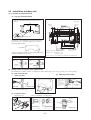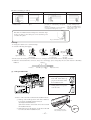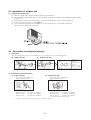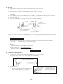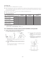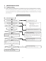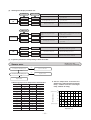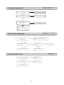
1
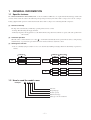
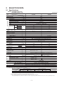
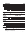
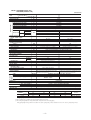
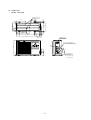
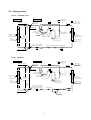
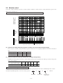
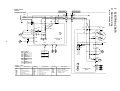
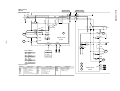
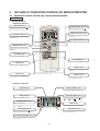
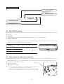
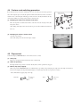
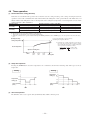
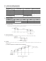
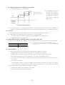
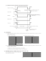
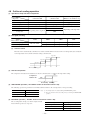
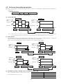
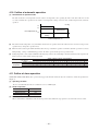
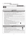
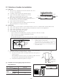
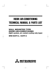
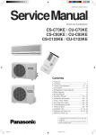
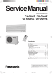
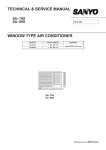
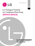
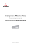
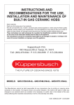
Manual No. ’07 . SRK-T . 064
TECHNICAL MANUAL
Collection data
WALL MOUNTED TYPE
ROOM AIR-CONDITIONER
(Split system, air to air heat pump type)
SRK20HG
SRK28HG
SRK40HG
-
3-
CONTENTS
1. GENERAL INFORMATION .............................................................................. 1
1.1 Specific features ....................................................................................... 1
1.2 How to read the model name ................................................................... 1
2. SELECTION DATA...........................................................................................
2.1 Specifications ...........................................................................................
2.2 Range of usage & limitations ..................................................................
2.3 Exterior dimensions .................................................................................
2.4 Piping system ...........................................................................................
2.5 Selection chart ..........................................................................................
2
2
5
5
7
8
3. ELECTRICAL DATA ........................................................................................ 9
3.1 Electrical wiring ........................................................................................ 9
4. OUTLINE OF OPERATION CONTROL BY MICROCOMPUTER ................... 11
4.1 Operation control function by remote control switch ........................... 11
4.2 Unit ON/OFF button .................................................................................. 12
4.3 Power blackout auto restart function ..................................................... 12
4.4 Custom cord switching procedure ......................................................... 13
4.5 Flap control ............................................................................................... 13
4.6 Timer operation ......................................................................................... 14
4.7 Outline of heating operation .................................................................... 15
4.8 Outline of cooling operation .................................................................... 18
4.9 Outline of dehumidifying operation ........................................................ 19
4.10 Outline of automatic operation ................................................................ 20
4.11 Outline of clean operation ....................................................................... 20
4.12 Protective control function ...................................................................... 21
5. APPLICATION DATA ....................................................................................... 23
5.1 Selection of location for installation ....................................................... 24
5.2 Installation of indoor unit ......................................................................... 25
5.3 Installation of outdoor unit ...................................................................... 28
5.4 Connection of refrigerant piping ............................................................. 28
5.5 Test run ...................................................................................................... 30
5.6 Precautions for wireless remote control installation and
operation ................................................................................................... 30
6. MAINTENANCE DATA .................................................................................... 31
6.1 Trouble shooting ....................................................................................... 31
6.2 Servicing .................................................................................................... 36
-
1-
1
GENERAL INFORMATION
1.1 Specific features
The “MITSUBISHI HEAVY INDUSTRIES, LTD.” room air-conditioner: SRK series are of split and wall mounted type and the unit
consists of indoor unit and outdoor unit with refrigerant precharged in factory. The indoor unit is composed of room air cooling or
heating equipment with operation control switch and the outdoor unit is composed of condensing unit with compressor.
(1) Remote control flap
The flap can be automatically controlled by operating wireless remote control.
¡ Swing: This will swing the flap up and down.
¡ Memory flap: Once the flap position is set, the unit memorizes the position and continues to operate at the same position from
the next time.
(2) Automatic Operation
When the remote control switch is set on “auto(
) ”, it will either automatically decide operation mode such as cooling, heating
and thermal dry, or operate in the operation mode before it has been turned to automatic control.
(3) Self diagnosis function
¡ We are constantly trying to do better service to our customers by installing such judges that show abnormality of operation as
follows.
RUN light
1 time flash
TIMER light
ON
Heat exchanger sensor error
2 time flash
Room temperature sensor error
6 time flash
Indoor fan motor error
RUN light
keeps flashing
RUN light
ON
TIMER light
Outdoor (LED)
1 time flash
OFF
2 time flash
OFF
4 time flash
OFF
Discharge pipe sensor error
2 time flash
2 time flash
Trouble of outdoor unit
5 time flash
5 time flash
Over heat of compressor
6 time flash
6 time flash
Error of signal transmission
1.2 How to read the model name
Example :
SR K 20 H G
Series No.
Heat pump type
Product capacity
Wall mounted type
Split type room air-conditioner
-
1-
Outdoor temperature sensor error
Outdoor unit heat exchanger
sensor error
2
SELECTION DATA
2.1 Specifications
Model SRK20HG (Indoor unit)
SRC20HG (Outdoor unit)
(220/230/240V)
Model
SRK20HG
Item
Refrigerant
piping
Operation data(1)
Cooling capacity(1)
Heating capacity(1)
Power source
Cooling input
Running current (Cooling)
Heating input
Running current (Heating)
Inrush current
COP
Sound level
Cooling
Power level
Noise level
Sound level
Heating
Power level
Exterior dimensions
Height × Width × Depth
Color
Net weight
Refrigerant equipment
Compressor type & Q’ty
Motor
Starting method
Heat exchanger
Refrigerant control
Refrigerant(3)
Refrigerant oil
Deice control
Air handling equipment
Fan type & Q’ty
Motor
(Cooling)
Air flow (at High)
(Heating)
Air filter, Q’ty
Shock & vibration absorber
Electric heater
Operation control
Operation switch
Room temperature control
Pilot lamp
Safety equipment
O.D
Connecting method
Attached length of piping
Insulation
Drain hose
Power source cord
Size × Core number
Connecting method
Accessories (included)
Optional parts
Connection wiring
W
W
SRC20HG
2070
2360
1 Phase, 220/230/240V, 50Hz
0.655
2.9/3.1/3.3
0.64
2.9/3.1/3.3
15.5
Cooling: 3.16 Heating: 3.69
Hi: 35 , Me: 28 , Lo: 26
53
Hi: 34 , Me: 31 , Lo: 27
53
kW
A
kW
A
A
dB
44
59
45
59
mm
268 × 790 × 199
540 × 780 × 290
kg
Fine snow
8.5
Stucco white
28
–
2RS127D5AA04 (Rotary type) × 1
kW
–
0.6
–
Line starting
Louver fins & inner grooved tubing
Straight fin & inner grooved tubing
Capillary tubes
R22 0.73 (Pre-Charged up to the piping length of 7m)
0.29 (ATMOS NM56M or SUNISO 4GDID)
Microcomputer control
kg
R
W
CMM
Tangential fan × 1
Propeller fan × 1
14
7.5
7.5
Polypropylene net (washable) × 2
–
–
14
27
27
–
Cushion rubber (for compressor)
–
Wireless-Remote control
–
Microcomputer thermostat
–
RUN (Green), TIMER (Yellow), HI POWER (Green), ECONO (Orange)
Frost protection, Serial signal error protection
Fan motor error protection
mm (in)
Compressor overheat protection, High pressure
control, Serial signal error protection
Liquid line: φ6.35 (1/4″) Gas line: φ9.52 (3/8″)
Flare connecting
Liquid line: 0.4 m
–
Gas line : 0.33 m
Necessary (Both sides)
Connectable
2 m (3 cores with Earth)
1.5 mm2 × 4 cores (Including earth cable)
Terminal block (Screw fixing type)
Mounting kit, Clean filter (Natural enzyme filter × 1, Photocatalytic washable deodorizing filter × 1)
–
Notes (1) The data are measured at the following conditions.
Item
Operation
Cooling
Heating
Indoor air temperature
DB
WB
27ºC
19ºC
20ºC
–
Outdoor air temperature
DB
WB
35ºC
24ºC
7ºC
6ºC
Standards
ISO-T1, JIS C9612
ISO-T1, JIS C9612
The piping length is 7 m.
(2) The operation data are applied to the 220/230/240V districts respectively.
(3) The refrigerant quantity to be charged includes the refrigerant in 7 m connecting piping.
If the piping length is longer, when it is less than 10 m, add 20 g refrigerant per meter and when it is 10 to 15 m, add 30 g refrigerant per meter.
-
2-
Model SRK28HG (Indoor unit)
SRC28HG (Outdoor unit)
(220/230/240V)
Model
SRK28HG
Item
(1)
Refrigerant
piping
Operation data(1)
Cooling capacity
Heating capacity(1)
Power source
Cooling input
Running current (Cooling)
Heating input
Running current (Heating)
Inrush current
COP
Sound level
Cooling
Power level
Noise level
Sound level
Heating
Power level
Exterior dimensions
Height × Width × Depth
Color
Net weight
Refrigerant equipment
Compressor type & Q’ty
Motor
Starting method
Heat exchanger
Refrigerant control
Refrigerant(3)
Refrigerant oil
Deice control
Air handling equipment
Fan type & Q’ty
Motor
(Cooling)
Air flow (at High)
(Heating)
Air filter, Q’ty
Shock & vibration absorber
Electric heater
Operation control
Operation switch
Room temperature control
Pilot lamp
Safety equipment
O.D
Connecting method
Attached length of piping
Insulation
Drain hose
Power source cord
Size × Core number
Connecting method
Accessories (included)
Optional parts
Connection wiring
W
W
SRC28HG
2530
2670
1 Phase, 220/230/240V, 50Hz
0.77
3.6/3.4/3.2
0.685
3.2/3.0/2.8
16.4
Cooling: 3.29 Heating: 3.90
Hi: 39, Me: 33, Lo: 30
55
Hi: 39, Me: 33, Lo: 29
56
kW
A
kW
A
A
dB
45
60
44
60
mm
268 × 790 × 199
540 × 780 × 290
kg
Fine snow
8.5
Stucco white
31
–
2PS146D5BC04 (Rotary type) × 1
kW
–
0.7
–
Line starting
Louver fins & inner grooved tubing
Straight fin & inner grooved tubing
Capillary tubes
R22 0.89 (Pre-Charged up to the piping length of 7m)
0.32 (ATMOS NM56M or SUNISO 4GDID)
Microcomputer control
kg
R
W
CMM
Tangential fan × 1
Propeller fan × 1
14
8.5
9.5
Polypropylene net (washable) × 2
–
–
15
29
29
–
Cushion rubber (for compressor)
–
Wireless-Remote control
–
Microcomputer thermostat
–
RUN (Green), TIMER (Yellow), HI POWER (Green), ECONO (Orange)
Frost protection, Serial signal error protection
Fan motor error protection
mm (in)
Compressor overheat protection, High pressure
control, Serial signal error protection
Liquid line: φ6.35 (1/4″) Gas line: φ9.52 (3/8″)
Flare connecting
Liquid line: 0.4 m
–
Gas line : 0.33 m
Necessary (Both sides)
Connectable
2 m (3 cores with Earth)
1.5 mm2 × 4 cores (Including earth cable)
Terminal block (Screw fixing type)
Mounting kit, Clean filter (Natural enzyme filter × 1, Photocatalytic washable deodorizing filter × 1)
–
Notes (1) The data are measured at the following conditions.
Item
Operation
Cooling
Heating
Indoor air temperature
DB
WB
27ºC
19ºC
20ºC
–
Outdoor air temperature
DB
WB
35ºC
24ºC
7ºC
6ºC
Standards
ISO-T1, JIS C9612
ISO-T1, JIS C9612
The piping length is 7 m.
(2) The operation data are applied to the 220/230/240V districts respectively.
(3) The refrigerant quantity to be charged includes the refrigerant in 7 m connecting piping.
If the piping length is longer, when it is less than 10 m, add 20 g refrigerant per meter and when it is 10 to 15 m, add 30 g refrigerant per meter.
-
3-
Model SRK40HG (Indoor unit)
SRC40HG (Outdoor unit)
(220/230/240V)
Model
SRK40HG
Item
Refrigerant
piping
Operation data(1)
Cooling capacity(1)
Heating capacity(1)
Power source
Cooling input
Running current (Cooling)
Heating input
Running current (Heating)
Inrush current
COP
Sound level
Cooling
Power level
Noise level
Sound level
Heating
Power level
Exterior dimensions
Height × Width × Depth
Color
Net weight
Refrigerant equipment
Compressor type & Q’ty
Motor
Starting method
Heat exchanger
Refrigerant control
Refrigerant(3)
Refrigerant oil
Deice control
Air handling equipment
Fan type & Q’ty
Motor
(Cooling)
Air flow (at High)
(Heating)
Air filter, Q’ty
Shock & vibration absorber
Electric heater
Operation control
Operation switch
Room temperature control
Pilot lamp
Safety equipment
O.D
Connecting method
Attached length of piping
Insulation
Drain hose
Power source cord
Size × Core number
Connecting method
Accessories (included)
Optional parts
Connection wiring
W
W
SRC40HG
3500
3700
1 Phase, 220/230/240V, 50Hz
1.09
5.0/4.8/4.6
1.09
5.0/4.8/4.6
27.0
Cooling: 3.21 Heating: 3.39
Hi: 40, Me: 38, Lo: 34
56
Hi: 40, Me: 38, Lo: 34
57
kW
A
kW
A
A
dB
48
63
50
64
mm
268 × 790 × 199
540 × 780 × 290
kg
Fine snow
8.5
Stucco white
38
–
2KS206D3AC04 (Rotary type) × 1
kW
–
0.95
–
Line starting
Louver fins & inner grooved tubing
Straight fin & inner grooved tubing
Capillary tubes
R22 1.1 (Pre-Charged up to the piping length of 7m)
0.41 (ATMOS NM56M or SUNISO 4GDID)
Microcomputer control
kg
R
W
CMM
Tangential fan × 1
Propeller fan × 1
14
9.0
10.0
Polypropylene net (washable) × 2
–
–
22
32
32
–
Cushion rubber (for compressor)
–
Wireless-Remote control
–
Microcomputer thermostat
–
RUN (Green), TIMER (Yellow), HI POWER (Green), ECONO (Orange)
Frost protection, Serial signal error protection
Fan motor error protection
mm (in)
Compressor overheat protection, High pressure
control, Serial signal error protection
Liquid line: φ6.35 (1/4″) Gas line: φ12.7 (1/2″)
Flare connecting
Liquid line: 0.4 m
–
Gas line : 0.33 m
Necessary (Both sides)
Connectable
2 m (3 cores with Earth)
1.5 mm2 × 4 cores (Including earth cable)
Terminal block (Screw fixing type)
Mounting kit, Clean filter (Natural enzyme filter × 1, Photocatalytic washable deodorizing filter × 1)
–
Notes (1) The data are measured at the following conditions.
Item
Operation
Cooling
Heating
Indoor air temperature
DB
WB
27ºC
19ºC
20ºC
–
Outdoor air temperature
DB
WB
35ºC
24ºC
7ºC
6ºC
Standards
ISO-T1, JIS C9612
ISO-T1, JIS C9612
The piping length is 7 m.
(2) The operation data are applied to the 220/230/240V districts respectively.
(3) The refrigerant quantity to be charged includes the refrigerant in 7 m connecting piping.
If the piping length is longer, when it is less than 10 m, add 20 g refrigerant per meter and when it is 10 to 15 m, add 30 g refrigerant per meter.
-
4-
2.2 Range of usage & limitations
Models
All models
Item
Indoor return air temperature
(Upper, lower limits)
Cooling operation : Approximately 21 to 32˚C
Heating operation : Approximately 15 to 30˚C
Outdoor air temperature
(Upper, lower limits)
Cooling operation : Approximately 21 to 43˚C
Heating operation : Approximately - 5 to 21˚C
Refrigerant line (one way) length
Max. 15m
Max. 5m (Outdoor unit is higher)
Max. 5m (Outdoor unit is lower)
Vertical height difference between
outdoor unit and indoor unit
Rating ± 10%
Power source voltage
Voltage at starting
Min. 85% of rating
Max. 10 times/h
(Inching prevention 3 minutes)
Frequency of ON-OFF cycle
ON and OFF interval
Max. 3 minutes
2.3 Exterior dimensions
(1) Indoor unit
Models All models
Unit: mm
A
®
790
199
3
9
60
268
Piping hole right(left)
Terminal block
138
450
206.5
202
450
133.5
102.5
585
7.5
43.2
39.3
102.5
45
53.5
(
Pipng for Gas
53.5
20, 28 : ø9.52
40 : ø12.7
380.6
)
Pipng for Liquid 448.6 (ø6.35)
VIEW A
Drain hose 520 (ø16)
Piping hole (ø65)
Piping hole (ø65)
-
5-
27
45
60
45
252.2
60
8.3
44.5
44.5
200
788
17.5
(2) Outdoor unit
Drain holes (ø20)
50
12
111.4
99.4
290
312.5
350
43.1
313.1
23.5
Models All models
104.9
14
349.5
439.1
510
780
165.1
18.9
61.9
2-16×12
Terminal block
Service valve (Liquid)
Flare connection ø6.35 (1/4'')
33.5
540
138.4
42.5
95.9
14
40˚
40˚
-
Service valve (Gas)
Flare connection
20, 28: ø9.52 (3/8'')
40: ø12.7 (1/2'')
6-
2.4 Piping system
Models
SRK20HG, 28HG
Indoor unit
Outdoor unit
Flare connecting
Piping
(Gas)
ø9.52
Cooling cycle
Heating cycle
Service valve
(Gas)
Outdoor air
temp. sensor
Check joint
4 way valve
Accumulator
Muffler
Room temp.
sensor
Discharge temp.
sensor
Heat
exchanger
sensor
Heat
exchanger
Heat
exchanger
Compressor
Piping
(Liquid)
ø6.35
Heat exchanger
sensor
Service valve (Liquid)
Capillary tube Capillary tube Capillary tube
Strainer
Flare connecting
Model
SRK40HG
Indoor unit
Outdoor unit
Flare connecting
Piping
(Gas)
ø12.7
Cooling cycle
Heating cycle
Service valve
(Gas)
Outdoor air
temp. sensor
Check joint
4 way valve
Accumulator
Room temp.
sensor
Muffler
Heat
exchanger
sensor
Discharge temp.
sensor
Heat
exchanger
Heat
exchanger
Compressor
Piping
(Liquid)
ø6.35
Service valve (Liquid)
Capillary tube
Flare connecting
Strainer
Check valve
-
7-
Heat exchanger
sensor
2.5 Selection chart
Correct the cooling and heating capacity in accordance with the conditions as follows. The net cooling and heating capacity can be
obtained in the following way.
Net capacity = Capacity shown on specification ✕ Correction factors as follows.
(1) Coefficient of cooling and heating capacity in relation to temperatures
Coefficient of cooling &
Heating capacity in
relation to temperature
1.3
1.2
Cooling
1.1
1.0
Heating
0.9
0.8
0.7
0.6
Outdoor air D.B.
temperature
˚C D.B.
Cooling operation
Applicable range
43
40
35
30
25
21
16
18
20
22
24
Indoor air D.B.
temperature
˚C D.B.
Heating operation
Indoor air W.B. temperature ˚C W.B. ISO-T1 Standard Condition
27
25
20
15
20
-5
0
5
Outdoor air W.B. temperature ˚C W.B.
10
15
ISO-T1 Standard Condition
(2) Correction of cooling and heating capacity in relation to one way length of refrigerant piping
It is necessary to correct the cooling and heating capacity in relation to the one way piping length between the indoor and outdoor
units.
Piping length [m]
7
10
15
Cooling
1.0
0.99
0.975
Heating
1.0
1.0
1.0
(3) Correction relative to frosting on outdoor heat exchanger during heating
In additions to the foregoing corrections (1), (2) the heating capacity needs to be adjusted also with respect to the frosting on the
outdoor heat exchanger.
Air inlet temperature of
outdoor unit in ˚CWB
-5
-3
-1
1
3
5
Adjustment coefficient
0.91
0.88
0.86
0.87
0.92
1.00
How to obtain the cooling and heating capacity
Example : The net cooling capacity of the model SRK20HG with the piping length of 15m, indoor wet-bulb temperature at 19.0˚C
and outdoor dry-bulb temperature 35˚C is Net cooling capacity =
2070
SRK20HG
-
8-
✕
0.975
Length 15m
✕
1.0
=
Factor by air
temperatures
2018 W
BR 1
FMI
CFI
Y/G
ZNR
BK
WH
J
N
CC
L
CM2 WH
52C
WH
CM
BK
U
3
CM1
CNW
Printed circuit
board
-
5
9-
SM
G
RD
CNU
WH 5
J
F
250V 3.15A
IC15
RD 3
RD
BK
52C
2/N
1
RD
N
52C-3
HEAT
EXCHANGER
52C-4 BR
WH
BK
Y/G
3 RD
WH
2/N
BK
1
Y
F
CNG
51C
52X1
CNM
CNE
BK
ZNR 250V 3.15A
CFO
Y
U
8
Color symbol
Black
BK
Blue
BL
Brown
BR
Light blue
LB
RD
Red
WH White
Y
Yellow
Y/G Yellow/Green
2
2
1 CNU
D.S
5
DISPLAY
WIRELESS
R-AMP
Th1
Th2
52X2
BACK UP SW
1 CNB
52X3
CM
F
FMI
FMO
SM
Th1
Th2
20S
3
52X1
Th4
Meaning of marks
Symbol
FMo
3
Parts name
Compressor motor
Fuse
Fan motor (Indoor)
Fan motor (Outdoor)
Flap motor
Room temp.sensor
Heat exch.sensor (Indoor unit)
Symbol
Th4
Th5
Th6
ZNR
20S
DS
TB
Parts name
Heat exch.sensor (Outdoor unit)
Outdoor air temp.sensor
Discharge pipe temp.sensor
Varistor
4 way valve (coil)
Diode stack
Terminal block
Symbol
CFI
CFO
51C
52C
52X1-3
Parts name
Capacitor for FMI
Capacitor for FMO
Motor Protector for CM
Magnetic contactor
Auxiliary relay
52X2
52X3
CNG
Printed circuit
board
Th5
Th6
ELECTRICAL DATA
Y/G
RD 3
WH
TB
3
TB
3.1 Electrical wiring
Outdoor unit
Indoor unit
BR
LB
Y/G
Models SRK20HG, 28HG
Power source
1 Phase
220/230/240V 50Hz
Outdoor unit
Indoor unit
TB
Y/G
RD 3
WH
2/N
FMI
CNU
CFI
Y/G
RD
J
ZNR
N
CC
L
CM2 WH
52C
U
3
WH
CM
CM1 BK
CNW
Printed circuit
board
-
5
10 -
SM
G
RD
RD 3
J
F
250V 3.15A
IC15
WH 5
BR 1
RD
BK
52C
Y/G
3 RD
WH
2/N
BK
1
BK
N
52C-3
HEAT
EXCHANGER
52C-4 BR
WH
BK 1
TB
WH
BR
LB
Y/G
Model SRK40HG
Power source
1 Phase
220/230/240V 50Hz
52X1
CNM
CNE
Y
F
CNG
ZNR 250V 3.15A
CFO
Y
U
8
Color symbol
BK
Black
Blue
BL
BR
Brown
Light blue
LB
RD
Red
WH White
Y
Yellow
Y/G Yellow/Green
2
2
1 CNU
D.S
5
DISPLAY
WIRELESS
R-AMP
Th1
Th2
FMo
3
52X2
BACK UP SW
1 CNB
52X3
20S
3
52X1
Th4
Meaning of marks
Symbol
CM
F
FMI
FMO
SM
Th1
Th2
Parts name
Compressor motor
Fuse
Fan motor (Indoor)
Fan motor (Outdoor)
Flap motor
Room temp.sensor
Heat exch.sensor (Indoor unit)
Symbol
Th4
Th5
Th6
ZNR
20S
DS
TB
Parts name
Heat exch.sensor (Outdoor unit)
Outdoor air temp.sensor
Discharge pipe temp.sensor
Varistor
4 way valve (coil)
Diode stack
Terminal block
Symbol
CFI
CFO
52C
52X1-3
Parts name
Capacitor for FMI
Capacitor for FMO
Magnetic contactor
Auxiliary relay
52X2
52X3
CNG
Printed circuit
board
Th5
Th6
4
OUTLINE OF OPERATION CONTROL BY MICROCOMPUTER
4.1 Operation control function by remote control switch
Remote control
Models All models
◆ Operation selection
FAN SPEED button
OPERATION MODE select button
Each time the button is pushed, the
indicator is switched over in turn.
Each time the button pushed, the
indicator is switched over in turn.
ON/OFF (luminous) button
HI POWER/ECONO button
Press for starting operation, press again
for stopping.
This button changes the HIGH POWER/
ECONOMY mode.
AIR FLOW (UP/DOWN) button
This button changes the air flow (up/down) mode.
TEMPERATURE button
This button sets the room temperature.
(This button changes the present time and
TIMER time.)
ON TIMER button
This button selects ON TIMER operation.
OFF TIMER button
This button selects OFF TIMER operation.
SLEEP button
This button selects to SLEEP operation.
RESET switch
Switch for resetting microcomputer and
setting time.
· The above illustration shows all controls, but in practice
CLEAN switch
only the relevant parts are shown.
This switch changes the CLEAN mode.
CANCEL button
This button cancels the ON timer, OFF
timer, and SLEEP operation.
◆ Indication selection
ON/OFF TIMER indicator
CLEAN indicator
Indicates during CLEAN operation.
Indicates during ON/OFF TIMER operation.
SLEEP indicator
OPERATION MODE indicator
Indicates selected operation with
lamp.
[ (Auto) · (Cool) ·
(Heat) · (Dry)]
Indicates during SLEEP operation.
TEMPERATURE indicator
TIME indicator
Indicates set temperature.
(Does not indicate temperature when operation
mode is on AUTO)
Indicates present time or timer setting time.
AIR FLOW indicator
FAN SPEED indicator
Indicates set air flow rate with
lamp.
Shows selected flap mode.
HI POWER/ECONO MODE indicator
Indicates during HIGH POWER/ECONOMY
mode operation.
-
11 -
Unit indication selection
Models All models
RUN light (green)
Illuminates during operation
and CLEAN operation.
TIMER light (yellow)
Illuminates during TIMER operation.
HI POWER light (green)
Illuminates during HIGH POWER operation.
ECONO light (orange)
Illuminates during ECONOMY operation.
4.2 Unit ON/OFF button
When the remote control batteries become weak, or if the remote control is lost or malfunctioning, this button may be used to turn the
unit on and off.
(1) Operation
Push the button once to place the unit in the automatic mode. Push it once more to turn the unit off.
(2) Details of operation
The unit will go into the automatic mode in which it automatically determines, from room temperature (as detected by sensor),
whether to go into the cooling, thermal dry or heating modes.
Function
Operation mode
Room temperature
setting
Cooling
About 24ºC
Thermal dry
About 24ºC
Heating
About 26ºC
Fan speed
Flap
Timer switch
Auto
Auto
Continuous
Unit ON/OFF button
4.3 Power blackout auto restart function
(1)
Power blackout auto restart function is a function that records the operational status of the air-conditioner immediately prior to it
being switched off by a power cut, and then automatically resumes operations at that point after the power has been restored.
(2)
The following settings will be cancelled:
Jumper wire (J7)
(a) Timer settings
(b) High-power operations
Notes (1) The power blackout auto restart function is set at on when the air-conditioner is shipped from the
factory. Consult with your dealer if this function needs to be switched off.
(2) When power failure ocurrs, the timer setting is cancelled. Once power is resumed, reset the timer.
(3) If the jumper wire (J7) “AUTO RESTART” is cut, auto restart is disabled. (See the diagram at right)
-
12 -
4.4 Custom cord switching procedure
If two wireless remote controls are installed in one room, in order to prevent wrong operation
Jumper wire (J6)
due to mixed signals, please modify the printed circuit board in the indoor unit’s control box
and the remote control using the following procedure. Be sure to modify both boards. If only
one board is modified, receiving (and operation) cannot be done.
(1) Modifying the indoor unit’s printed circuit board
Take out the printed circuit board from the control box and cut off jumper wire (J6)
using wire cutters.
After cutting of the jumper wire, take measures to prevent contact with the other the lead
wires, etc.
(2) Modifying the wireless remote control
(a) Remove the battery.
(b) Cut the jumper wire shown in the figure at right.
Cut
4.5 Flap control
Control the flap by AIRFLOW button on the wireless remote control.
(1) Swing flap
Flap moves in upward and downward directions continuously.
(2) When not operating
The flap returns to the position of air flow directly below, when operation has stopped.
(3) Memory flap (Flap stopped)
When you press the AIRFLOW button once while the flap is operating, it stops swinging at an angle. Since this angle is memorized
in the microcomputer, the flap will automatically be set at this angle when the next operation is started.
¡ Recommendable stopping angle of the flap
COOL•DRY
HEAT
Horizontal
blowing
-
13 -
Slant forward
blowing
4.6 Timer operation
(1) Comfortable timer setting (ON timer)
If the timer is set at ON when the operation select switch is set at the cooling or heating, or the cooling or heating in auto mode
operation is selected, the comfortable timer starts and determines the starting time of next operation based on the initial value of 15
minutes and the relationship between the room temperature at the setting time (temperature of room temperature sensor) and the
setting temperature. (Max. 60 minutes)
Operation mode
At cooling
At heating
3 < Room temp. – Setting temp.
Operation start time correction value (Min.)
<3
1 < Room temp. – Setting temp. =
+5
No change
3 < Setting temp. – Room temp.
<3
2 < Setting temp. – Room temp. =
No change
+5
<1
Room temp. – Setting temp. =
–5
Setting temp. – Room temp. <
=2
–5
Notes (1) At 5 minutes before the timer ON time, operation starts regardless of the temperature of the room temperature sensor (Th1).
(2) This function does not operate when in the Dry or Auto Dry mode.
However, the operation in item (1) does operate in the Auto Dry mode.
(3) During the comfortable timer operation, both the RUN light and TIMER light illuminate and the TIMER light goes off after expiration of the timer, ON setting
time.
(Example) Heating
Corrects the starting time of next operation by
calculating the temperature difference.
Setting temperature
¡ If the difference (= Setting temperature – Room temperature) is 4ºC, the correction value is found to be +5 minutes from the table shown above so that the starting time
of next operation is determined as follows:
15 min. earlier + 5 min. = 20 min. earlier
↑
↑
Current operation
Correction value
start time
Room temperature
Operation starting time
Time
15 min.
earlier
10 min.
earlier
5 min.
earlier
Setting time
(2) Sleep timer operation
Pressing the SLEEP button causes the temperature to be controlled as shown in the following chart with respect to the set
temperature.
Cooling
Heating
Temperature
setting (˚C)
Temperature
setting (˚C)
0
+1.0
-1.0
0
-2.0
-1.0
-3.0
-6.0
Timer operation
(time)
0
1.0
Timer operation
(time)
2.0
Start
0
Start
(3) OFF timer operation
The Off timer can be set at a specific time (in 10-minute units) within a 24-hour period.
-
14 -
0.5
1.0
2.0
4.7 Outline of heating operation
(1) Operation of major functional components
Functional
components
Indoor fan motor
Item
When the compressor
command is OFF
When the compressor
command is ON
When the compressor goes
OFF due to an anomalous stop.
ON
ON
OFF
Flaps
ON or OFF
ON or OFF
Stop position control
Display
Lights up
Lights up
Lights up or flashes
52C
ON
ON
Outdoor fan motor
ON
Depending on the stop mode
4-way valve
Depending on the stop mode
ON
(2) Fan speed switching
Fan speed switching
AUTO
Flow control
Swing flap
Auto fan control
Swing stop
HIGH
MED
LOW
Speed 7
Speed 5
Speed 3
Speed 7
Speed 5
Speed 3
(a) Auto fan control
The indoor fan is automatically controlled in accordance with the difference between the room temperature (detected by the
room temperature sensor) and the thermostat setting as shown below.
Speed 7
Speed 5
Speed 3
-5
-4
-3
-2
-1
0
Thermostat setting point
(3) Thermostat operation
The compressor and outdoor fan and turned on and off as shown below according to the temperature setting.
ON
Compressor
Outdoor fan
OFF
+1
Set temp. Room temp.
(4) Hot keep
This function controls the indoor unit fan speed as shown below in accordance with the temperature sensed by the indoor heat
exchanger sensor.
(a) When the compressor and outdoor unit fan are operating
Speed 9
Speed 7
Auto fan control,
or the set fan speed
Speed 5
Speed 3
OFF
<SRK20HG>
<SRK28HG>
<SRK40HG>
15
15
18
20
25
23
25
30
30
30
34
37
Indoor heat exchanger temp. (˚C)
-
15 -
34
40
43
(b) When the compressor and outdoor fan are stopped
1) While the compressor operation is delayed.
2) Up until 5 minutes have passed
Speed 9
Speed 5
Speed 3
Speed 3
Auto fan control,
or the set fan speed
since the end of a compressor
start delay operation, when 52C
goes OFF, the indoor unit’s fan
OFF
speed changes forcibly from
OFF to speed 1.
25
30
30
<SRK20HG>
<SRK28HG>
<SRK40HG>
30
34
37
34
40
43
Indoor heat exchanger temp. (˚C)
(c)
To accomplish rapid recovery from the thermostat off state, after the compressor and outdoor unit’s fan go OFF, the set
temperature is raised by 1ºC until 1 minute passes after the hot keep end temperature has been reached following restarting.
(5)
Hot spurt
(a)
For 40 minutes after a heating operation begins, the system runs with set temperature raised by 2ºC.
(b)
In the following cases, this function is canceled and does not activate afterwards.
1) When the compressor and outdoor unit fan have been turned OFF by the thermostat going off.
2) During high pressure control operation.
(6)
HIGH POWER operation (“HI POWER” button on the remote control : ON)
The system runs under the following conditions for 15 minutes without relation to the set temperature or the fan speed setting.
(7)
Indoor unit fan
Speed 9 fixed
Outdoor unit fan
ON
Compressor
ON
Notes (1) Room temperature is not adjusted during the HIGH POWER operation.
(2) Protective function will actuate with prioriy even during the HIGH POWER
operation.
Defrost operation
(a)
Starting conditions (Defrost operation begins when all the following conditions are satisfied.)
1 40 minutes have passed since the heating operation began. (Accumulated operation time)
2 40 minutes have passed since the previous defrosting operation ended. (Accumulated operation time)
3 The outdoor unit heat exchanger sensor temperature is –5ºC or lower continuously for 3 minutes.
4 The difference between the outdoor air temperature sensor temperature and the outdoor heat exchange sensor tempera> 4.5ºC.
ture is =
5 The compressor is running.
Also, the number of times the compressor goes OFF is counted, and when it reaches 10 or more times, if the conditions
in 1, 2 and 3 above (except that the outdoor heat exchanger sensor temperature is –1ºC), the defroster operation starts.
(b)
End conditions (when either of the following conditions is satisfied)
1 Outdoor heat exchanger sensor temperature: 9ºC or higher
2 Defrosting operation has continued for 10 minutes.
-
16 -
(c) Operation of functinal components during defrosting operation
ON
Compressor command
OFF
Hot keep
Controlled by the indoor heat
exchanger temperature
Hot keep
ON
Indoor unit fan
OFF
The chart at left is for reference.
Hot keep control governs operation
during heating.
Lit
RUN light
Flashes
ON
Outdoor unit fan
OFF
ON
110 sec.
4-way valve
OFF
Defrost start operation 120 sec.
Defrost operation
120 sec.
Operation after defrost is ended.
Recovery
temperature
(9ºC)
Normal heating operation
(defrost recovery)
(8) Forced defrost
(a)
During trial operation, if defrost operation is performed, defrost operation can be performed only once time, in accordance
with the following operation.
2) Functional components operation
1) Remote control operation
ON
Heating
4-way valve
OFF
19˚C
Indoor unit fan
OFF
Run
Operation mode
Set temperature
Fan speed select
Low
Flap
Fully closed
Air flow setting
Swing
Outdoor unit fan
OFF
On timer
ON
Display
Same as defrost
Current time
On timer time
(b)
Compressor
Operation
On after 180 min.condition
If remote control operation is performed, for 1 minute after 3-minute timer operation, the operation is canceled if one of the
following conditions is satisfied.
1 Outdoor heat exchanger sensor temperature: 14ºC or higher
2 10 minutes has passed (including the 1 minute of forced operation).
(9) ECONOMY operation ( “ECONO” button on the remote control : ON)
The set temperature changes as shown at right and the
indoor unit fan runs at speed 4.
-
Running time
Set temperature compensation
Running start ~ 1 hour
Set temperature -1.0
1~2 hours
Set temperature -2.0
2 hours ~
Set temperature -2.5
17 -
4.8 Outline of cooling operation
(1)
Operation of major functional components
Functional
components
Indoor fan motor
Item
When the compressor
command is OFF
When the compressor
command is ON
When the compressor goes
OFF due to an anomalous stop.
ON
ON
OFF
Flaps
ON or OFF
ON or OFF
Stop position control
Display
Lights up
Lights up
Lights up or flashes
52C
ON
ON
Outdoor fan motor
4-way valve
ON
Depending on the stop mode
Depending on the stop mode
OFF
(2) Fan speed switching
Fan speed switching
AUTO
Flow control
Swing flap
Swing stop
Auto fan control
HIGH
MED
LOW
Speed 6
Speed 4
Speed 2
Speed 6
Speed 4
Speed 2
(a) Auto fan control
The indoor fan is automatically controlled in accordance with the difference between the room temperature (detected by the
room temperature sensor) and the termostat setting as shown below.
Speed 6
Speed 5
Speed 4
Speed 2
+1
Thermostat setting point
+2
+3
+4
(3) Thermostat operation
The compressor and outdoor fan and turned on and off as shown below according to the temperature setting.
ON
Compressor
Outdoor fan
OFF
-1
Room temp. Set temp.
(4) HIGH POWER operation ( “HI POWER” button on the remote control : ON)
The following operation is performed for 15 minutes without relation to the set temperature or fan speed setting.
Indoor unit fan
Speed 8 fixed
Outdoor unit fan
ON
Compressor
ON
Notes (1) Room temperature is not adjusted during the HIGH POWER operation.
(2) Protective functions will actuate with priority even during the HIGH POWER
operation.
(5) ECONOMY operation ( “ECONO” button on the remote control : ON)
The set temperature changes as shown at right, and the
indoor unit fan speed is set on speed 2.
-
Running time
Set temperature compensation
Running start ~ 1 hour
Set temperature +0.5
1~2 hours
Set temperature +1.0
2 hours ~
Set temperature +1.5
18 -
4.9 Outline of dehumidifying operation
(1) Choose the appropriate operation block area by the difference between room temperature and thermostat setting temperature as
shown below.
¡ Operation block area
D block
C block
–2
Room temp.
B block
A block
0
+3
– Setting temp.(deg)
(2) Start up operation
C.D block
A.B block
Compressor ON
and
OFF
outdoor fan
Compressor ON
and
outdoor fan OFF
Speed 2
Speed 2
Speed 1
Indoor fan
OFF
20
Indoor fan
seconds
0
3
Start
6
9
OFF
12 minutes
12 minutes
0
Temperature check
Temperature check
Start
Operation block decision
Note (1) Thermostat operation is performed in A, B block. When compressor and indoor fan stop by thermostat operation within 12 minutes from start, temperature
check is performed by operating indoor fan at speed 1 for 20 seconds before finishing 12 minutes and allowing decision of next operation block.
(3) DRY operation
After finishing start up operation described in (2) above, thermal dry operation is performed at 8 minutes intervals, according to the
difference between room temperature and thermostat setting temperature as shown below.
Beside, 1 cycle of this operating time consists of 8 minutes, 7 cycle operation is performed then.
D block
C block
Compressor ON
and
outdoor fan OFF
Speed 2
Speed 1
Indoor fan
OFF
Compressor
and
OFF
outdoor fan
Speed 1
Indoor fan
OFF
20 seconds
8 minutes
0
Start
0
Temperature check
20 seconds
3
Start
8 minutes
Temperature check
Operation block decision
B block
A block
Compressor ON
and
outdoor fan OFF
Compressor ON
and
outdoor fan OFF
Speed 2
Indoor fan Speed 1
Speed 2
Indoor fan
OFF
OFF
20 seconds
0
Start
4
0
8 minutes
Temperature check
8 minutes
Start
Temperature check
Operation block decision
(4) ECONOMY operation ( “ECONO” button on the remote control : ON)
The set temperature changes as shown at right, and the
indoor unit fan speed is set on speed 2.
-
Running time
Set temperature compensation
Running start ~ 1 hour
Set temperature +0.5
1~2 hours
Set temperature +1.0
2 hours ~
Set temperature +1.5
19 -
4.10 Outline of automatic operation
(1)
Determination of operation mode
The unit checks the room temperature and the outdoor air temperature after operating the indoor and outdoor blowers for 20
seconds, determines the operation mode and the room temperature setting correction value, and then begins in the automatic
operation.
Cooling
27.5
25.5
Dehumidifying
Room temperature (˚C)
19.5
Heating
30
18
Outdoor temperature (˚C)
(2) The unit checks the temperature every 30 minutes after the start of operation and, if the result of check is not same as the previous
operation mode, changes the operation mode.
(3) When the unit is started again within 30 minutes after the stop of automatic operation or when the automatic operation is selected
during heating, cooling or dehumidifying operation, the unit is operated in the previous operation mode.
(4) Setting temperature can be adjusted within the following range. There is the relationship as shown below between the signals of the
wireless remote control and the setting temperature.
Signals of wireless remote control (Display)
Setting
temperature
–6
–5
–4
–3
–2
–1
±0
+1
+2
+3
+4
+5
+6
Cooling
18
19
20
21
22
23
24
25
26
27
28
29
30
Dehumidifying
18
19
20
21
22
23
24
25
26
27
28
29
30
Heating
20
21
22
23
24
25
26
27
28
29
30
31
32
4.11 Outline of clean operation
COOL,DRY,AUTO (COOL,DRY); after operation has stopped, the moisture inside the dryer air conditioner, controls the production of
fungus etc.
(1)
Operating condition
‘Clean’ is switched ON, when the air conditioner receives a STOP signal.
(2)
(3)
Detail of operation
Compressor
OFF
Indoor fan motor
Speed 1
Outdoor fan motor
OFF
Flap
Fully closed
Reset condition
When control finishes 120 minutes after the Clean operation starts. When the stop signal is received from the remote control.
-
20 -
4.12 Protective control function
(1) Frost prevention for indoor heat exchanger (During cooling or dehumidifying)
(a)
Operating conditions
(i)
Indoor heat exchanger temperature (detected with Th2) is lower than 2.5ºC.
(ii)
3 minutes elapsed after the start of operation.
(b) Detail of anti-frost operation
Compressor
OFF
Indoor fan
(c)
Protects the fan tap just before frost prevention control
Outdoor fan
OFF
4-way valve
Stop mode
Reset condition: Indoor heat exchanger temperature (Th2) is higher than 8ºC.
(2) Indoor fan motor protection
When the air conditioner is operating and the indoor fan motor is turned ON, if the indoor fan motor has operated at 300 rpm or
under for more than 30 seconds, the unit enters first in the stop mode and then stops the entire system.
TIMER light illuminates simultaneously and the RUN light flashing 6 times at each 8-second.
(3) Three-minute forced operation
When the compressor begins operating the thermal operation is not effective for 3 minutes, so operation continues as is in the
operation mode. (After 3 minutes has passed the thermal operation is effective.)
However, stopping the compressor via a stop signal or protection control has priority.
(4) High-pressure control
The indoor heat exchanger sensor detection temperature controls the outdoor fan and compressor.
¡ When the indoor heat exchanger
temperature is >
= 58˚C
Outdoor fan
¡ When the indoor heat exchanger
temperature is >
= 62˚C
ON
Compressor
ON
OFF
OFF
<SRK20HG>
<SRK28HG>
<SRK40HG>
48
48
48
52
58
55
48
62
Indoor heat exchanger temp. (˚C)
Indoor heat exchanger temp. (˚C)
(5) Compressor overheat protection
If the discharge pipe temperature (sensed by Th6) exceeds the set temperature value, the compressor stops. If the temperature is 95ºC
or lower after a 3-minute delay, it starts again, but if this function is reactivated again within 60 minutes, it results in an abnormal stop.
Operation possible
Abnormal stop
95
125
Discharge pipe temperature (˚C)
-
21 -
(6) Serial signal transmission error protection
(a) Purpose: Prevents malfunction resulting from error on the indoor ↔ outdoor signals.
(b) Detail of operation: When the indoor unit controller ↔ outdoor unit controller signals cannot be received, the compressor
is stopped immediately. Simultaneously, the red LED on the printed circuit board of outdoor unit
controller flashing 6 times for 0.5 second at intervals of 8 seconds. Once the operation stops, it does
not start any more.
(TIMER light on the indoor unit flashing at the same time.)
(7) Sensor disconnection (room temperature, indoor heat exchanger, outdoor heat exchanger, outdoor air temperature, discharge pipe)
(a) Room temperature sensor
If the temperature detected by the room temperature sensor is –20ºC or lower continuously for 15 seconds or longer while
operation is stopped, an error indication is displayed.
(b) Indoor heat exchanger sensor
If the temperature detected by the indoor heat exchanger sensor is –20ºC or lower continuously for 15 seconds or longer
while operation is stopped, an error indication is displayed.
Also, if the temperature detected by the indoor heat exchanger sensor is –20ºC or lower continuously for 3 minutes after
heating operation has started, the indoor unit’s fan speed is forcibly raised to speed 5. After this, the air conditioner is stopped
if the detected temperature remains at –20ºC continuously for 40 minutes.
(c) Outdoor heat exchanger sensor
If the temperature detected by the outdoor heat exchanger sensor is –50ºC or lower continuously for 15 seconds or longer
while operation is stopped, an error indication is displayed.
Also, the air conditioner is stopped if the temperature detected by the outdoor heat exchanger sensor remains at –50ºC or
lower continuously for 40 minutes after heating operation has started.
(d) Outdoor air temperature sensor
If the temperature detected by the outdoor air temperature sensor is –40ºC or lower continuously for 15 seconds or longer
while operation is stopped, an error indication is displayed.
(e) Discharge pipe sensor
After the compressor has operated for 9 minutes continuously, if there is a disconnected signal for the discharge pipe sensor
detected temperature for 15 seconds (less than 7ºC), the compressor stops. After a 3-minute delay, it restarts, but if an
abnormality is detected 4 times continuously, the air conditioner is stopped fully and an error indication is displayed.
-
22 -
5
APPLICATION DATA
SAFETY PRECAUTIONS
¡ Please read these “Safety Precautions” first then accurately execute the installation work.
WARNING and
CAUTION , those points
¡ Though the precautionary points indicated herein are divided under two headings,
which are related to the strong possibility of an installation done in error resulting in death or serious injury are listed in the
WARNING section. However, there is also a possibility of serious consequences in relationship to the points listed in the
CAUTION section as well. In either case, important safety related information is indicated, so by all means, properly observe all
that is mentioned.
¡ After completing the installation, along with confirming that no abnormalities were seen from the operation tests, please explain
operating methods as well as maintenance methods to the user (customer) of this equipment, based on the owner’s manual.
Moreover, ask the customer to keep this sheet together with the owner’s manual.
WARNING
¡ To disconnect the appliance from the mains supply this appliance must be connected to the mains by means of
a circuit breaker or a switch (use a recognized 20A) with a contact separation of at least 3mm.
¡ The appliance shall be installed in accordance with national wiring regulations.
¡ When a plug is connected to the power cord, a plug conforming to the IEC60884-1 standard must be used.
¡ This system should be applied to places as households, residences and the like. Application to inferior environment such as engineering shop could cause equipment malfunction.
¡ Please entrust installation to either the company which sold you the equipment or to a professional contractor.
Defects from improper installations can be the cause of water leakage, electric shocks and fires.
¡ Execute the installation accurately, based on following the installation manual. Again, improper installations can
result in water leakage, electric shocks and fires.
¡ For installation, confirm that the installation site can sufficiently support heavy weight. When strength is insufficient, injury can result from a falling of the unit.
¡ For electrical work, please see that a licensed electrician executes the work while following the safety standards
related to electrical equipment, and local regulations as well as the installation instructions, and that only exclusive use circuits are used.
Insufficient power source circuit capacity and defective installment execution can be the cause of electric shocks
and fires.
¡ Accurately connect wiring using the proper cable, and insure that the external force of the cable is not conducted
to the terminal connection part, through properly securing it. Improper connection or securing can result in heat
generation or fire.
¡ Take care that wiring does not rise upward, and accurately install the lid/service panel. It’s improper installation
can also result in heat generation or fire.
¡ When setting up or moving the location of the air conditioner, do not mix air etc. or anything other than the
designated refrigerant (R22) within the refrigeration cycle.
Rupture and injury caused by abnormal high pressure can result from such mixing.
¡ Always use accessory parts and authorized parts for installation construction. Using parts not authorized by this
company can result in water leakage, electric shock, fire and refrigerant leakage.
¡ Ventilate the work area when refrigerant leaks during the operation.
Coming in contact with fire, refrigerant could generate toxic gas.
¡ Confirm after the foundation construction work that refrigerant does not leak.
If coming in contact with fire of a fan heater, a stove or movable cooking stove, etc., refrigerant leaking in the
room could generate toxic gas.
CAUTION
¡ Execute proper grounding. Do not connect the ground wire to a gas pipe, water pipe, lightning rod or a telephone
ground wire.
Improper placement of ground wires can result in electric shock.
¡ The installation of an earth leakage breaker is necessary depending on the established location of the unit.
Not installing an earth leakage breaker may result in electric shock.
¡ Do not install the unit where there is a concern about leakage of combustible gas.
The rare even of leaked gas collecting around the unit could result in an outbreak of fire.
¡ For the drain pipe, follow the installation manual to insure that it allows proper drainage and thermally insulate it
to prevent condensation. Inadequate plumbing can result in water leakage and water damage to interior items.
¡ Install the outdoor unit so that the aluminum fins on the air heat exchanger cannot be touched. Failure to
observe this may result in injury.
¡ Do not place objects near the outdoor unit or allow leaves to gather around the unit. If there are objects or leaves
around the outdoor unit, small animals may enter unit and contact electrical parts resulting in break down,
emission of smoke or flame.
-
23 -
5.1 Selection of location for installation
(1)
Indoor unit
(a)
(b)
(c)
(d)
(e)
(f)
(g)
(2)
Where there is no obstructions to the air flow and where the cooled
air can be evenly distributed.
A solid place where the unit or the wall will not vibrate.
A place where there will be enough space for servicing.
(Where space mentioned right can be secured)
Where wiring and the piping work will be easy to conduct.
The place where receiving part is not exposed to the direct rays of
the sun or the strong rays of the street lighting.
A place where it can be easily drained.
A place separated at least 1m away from the television or the radio.
(To prevent interference to images and sound.)
Right
side
Left
side
10 cm
5 cm
Outdoor unit
(a)
(b)
(c)
(d)
(e)
A place where good air circulation can be obtained and where rain, snow or sunshine will not directly strike the unit.
A place where discharged hot air or unit’s operating sound will not be a nuisance to the neighborhood.
A place where servicing space can be secured.
A place where vibration will not be enlarged.
Avoid installing in the following palces.
• A place near the bed room and the like, so that the operation noise will cause no trouble.
• A place where there is possibility of flammable gas leakage.
• A place exposed to strong wind.
• In a salt-laden atmosphere or a place where the generation of oil mist, vapor or fume is expected.
Air intake
10 cm
MIN
Air outlet
(f)
Notes (1) Blowing out port and suction port on the back side of the unit can be
installed at a distance of 10cm from walls.
In case the barrier is 1.2m or above in height, or is overhead, the
sufficient space between the unit and wall shall be secured.
(2) When the unit is installed, the space of the following dimension and
above shall be secured.
10 cm MIN
(
No obstacles
(Service
space for
electrical
parts)
Air
intake
(3)
6.5 cm
)
60 cm MIN
In heating operation, snow deposit on the heat-exchanger of outdoor unit must be
prevented for keeping the normal performance capacity.
1) Snow-hood on outdoor unit as in drawing, will reduce the frequency of
defrost operation.
When installing the snow hood, take care so that the air outlet of the snow
hood will not face directly into the most windy direction.
2) Design the base higher than possible snow deposit.
Snow hood
Height:
Must be over
the possible
snow deposit
height
Limitations for one way piping length and vertical
height difference.
Model
Item
One way piping length (R)
Vertical
height
difference (h)
Outdoor
unit is lower
Outdoor unit
is higher
All models
15 m
h
r
5m
5m
-
24 -
5.2 Installation of indoor unit
(1) Installation of installation board
Fixing of installation board
Look for the inside wall structures (Intersediate support or
pillar and firaly install the unit after level surface has been
checked.)
450
INSTALLATION SPACE (INDOOR UNIT)
(FRONT VIEW)
Unit : mm
65
39.3
43.2
Space
138
206.5
102.5
200
44.5
252.2
Mating mark for level surface
44.5
Adjustment of the installation board in the horizontal
direction is to be conducted with four screws in a
temporary tightened state.
7.5 for service
Space for
Indoor unit
service
100
Installation board
450
202
133.5
450
102.5
585
Space for
service
50
53.5
53.5
Piping for Gas 380.6
Piping for Liquid 448.6
Drain hose 520( 16)
Space * 15
for service
8.3
(a)
Standard hole
Piping hole( 65)
Piping hole( 65)
Piping for Liguid (20~50type) : ø6.35
Piping for Gas (20~35type) : ø9.52
(40, 50type) : ø12.7
Adjust so that board will be level by turning the board
with the standard hole as the center.
* Leave extra space on the right side to enable removal of the lid screw.
Fixing on concrete wall
Use of nut anchor
Use of bolt anchor
Nut
(M6)
Bolt
(M6 × 12)
Mounting
board
Max. 10
Mounting
board
(2) Drilling of holes and fixture sleeve (Option Parts)
When drilling the wall that contains a metal lath, wire lath or metal plate, be sure to use pipe hole sleeve sold separately.
(a)
Drill a hole with ø65
(b) Adjusting sleeve length
whole core drill
Cut off the sleeve
collar in case of
drawing piping out
to rear.
Indoor side
Cut off the sleeve
collar that can be
seen from beneath
the unit.
Outdoor side
Wall thickness
+ 1.5 cm
Note (1) Drill a hole with incline of 5 degree from
indoor side to outdoor side.
(c)
Install the sleeve
(Inserting sleeve)
(*Sleeve + *Inclined + *Sealing plate)
Turn to
tighten
View of sleeve when installed
Inclined
flange
Sealing
Sleeve
plate
Paste
Indoor side
Outdoor side
-
25 -
Indoor side
Outdoor side
(3)
Preparation of indoor unit
(a)
Mounting of connecting wires
1) Remove the lid(R).
2) Remove the wiring clamp.
3) Connect the connecting wire securely to the terminal block.
Use cables for interconnection wiring to avoid loosening of the
wires.
CENELEC code for cables. Required field cables.
H05RNR4G1.5 (Example) or 245IEC57
H Harmonized cable type
05 300/500 volts
R Natural-and/or synth, rubber wire insulation
N Polychloroprene rubber conductors insulation
R Standed core
4or5 Number of conductors
G One conductor of the cable is the earth conductor
(yellow/green)
1.5 Section of copper wire (mm2)
Terminal block
Clamp
Screw *
Lid
*Leave space to allow removal of this screw after installation.
1 Connect the connection wire securely to the terminal block. If the wire is not affixed completely, contact will be poor,
and it is dangerous as the terminal block may heat up and catch fire.
2 Take care not to confuse the terminal numbers for indoor and outdoor connections.
3 Affix the connection wire using the wiring clamp.
4) Fix the connecting wire by wiring clamp.
5) Attach the lid.
6) Close the air inlet panel.
(b) Installing the support of piping
[Shaping the piping]
[Taping of the exterior]
Piping
Drain hose
¡ Hold the bottom of the piping and fix direction before
stretching it and shaping it.
¡ Tape only the portion that goes through the wall.
Always tape the crossover wiring with the piping.
[Matters of special notice when piping from left or center/rear of the unit.]
[Top View]
Left-hand-sided-piping
Piping in the left rear direction
Right-hand-sided-piping
Piping in the right rear direction
Piping in the right direction
Piping in the left direction
Piping is possible in the rear,
left, left lear, left downward,
right or downward direction.
Right
Rear
Downward Left rear
Left
Left downward
-
26 -
[Drain hose changing procedures]
1. Remove the drain hose. 2. Remove the drain cap.
¡Remove the drain hose, ¡Remove it with hand or
making it rotate.
pliers.
3. Insert the drain cap.
4. Connect the drain hose.
¡Insert the drain cap which was removed at ¡I n s e r t t h e d r a i n h o s e
procedure “2” securely using a hexagonal
securely, makingit rotate.
wrench, etc.
Note: Be careful that if it is
Note: Be careful that if it is not inserted
not inserted securely, water
securely, water leakage may occur.
leakage may occur.
Gutter
Since this air conditioner has been designed to collect dew drops
on the rear surface to the drain pan, do not attach the power
cord above the gutter.
Pipe accommodation section
Drainage
¡ Arrange the drain hose in a downward angle.
¡ Avoid the following drain piping.
Odor from
the gurtter
Higher than specified
The drain hose
tip is in water.
Weavy
The gap to the ground
is 5 cm or less.
The drain hose tip is in
the gutter.
¡ Pour water to the drain pan located under the heat exchanger, and ensure that the water is discharged outdoor.
¡ When the extended drain hose is indoor, always use a shield pipe (to be arranged by the user) and ensure it is thermally
insulated.
Shield pipe
Drain hose
(c)
When it is exposed indoor.
Extended drain hose
Fixing of indoor unit
Installation Steps
1 Pass the pipe through the hole
in the wall, and hook the upper part of the indoor unit to
the installation board.
2 Gently push the lower part to
secure the unit.
¡ How to remove the indoor unit from the installation board
1 Push up at the marked portion of the indoor unit base
lower latch, and slightly pull it toward you.
(both right and left hand sides)
(The indoor unit base lower latch can be removed from
the installation board)
2 Push up the indoor unit upward. So the indoor unit will
be removed from the installation board.
-
27 -
Lid
The marked portion of the
indoor unit bese lower latch
5.3 Installation of outdoor unit
(1) Installation of outdoor unit
(a) Make sure that the unit is stable in installation. Fix the unit to stable base.
(b) When installing the unit at a higher place or where it could be toppled by strong winds, secure the unit firmly with foundation
bolts, wire, etc.
(c) Perform wiring, making wire terminal numbers conform to terminal numbers of indoor nuit terminal block.
(d) Connect using ground screw located near
mark.
(e) In areas where the temperatures drop below 0ºC for serveral continuous days, do not install a drain elbow.
(Water dischage could stop due to freezing.)
5.4 Connection of refrigerant pipings
(1) Preparation
Keep the openings of the pipes covered with tapes etc. to prevent dust, sand, etc. from entering them.
(a)
(b) Outdoor unit side
Indoor unit side
Dimension A
Liquid side
(ø6.35): 9.0 mm
Gas side
(ø9.52): 13.0 mm
(ø12.7): 16.2 mm
Press
(Do not
turn)
Remove
¡ Remove the flared nuts.
(on both liquid and gas sides)
Remove
¡ Remove the flared nuts.
(on both liquid and gas sides)
¡ Install the removed flared nuts to the pipes to be
connected, then flare the pipes.
(2) Connection of refrigerant piping
(a)
(b) Outdoor unit side
Indoor unit side
• Connect firmly gas and liquid side
pipings by Torque wrench.
• Connect firmly gas and liquid side
pipings by Torque wrench.
Spanner
for fixing
the piping)
Torque
wrench
• Specified torquing value:
Liquid side (ø6.35) : 14~18N·m (1.4~1.8kgf·m)
Gas side (ø9.52)
: 34~42N·m (3.4~4.2kgf·m)
Gas side (ø12.7)
: 49~61N·m (4.9~6.1kgf·m)
• Specified torquing value:
Liquid side (ø6.35) : 14~18N·m (1.4~1.8kgf·m)
Gas side (ø9.52)
: 34~42N·m (3.4~4.2kgf·m)
Gas side (ø12.7)
: 49~61N·m (4.9~6.1kgf·m)
• Use one more spanner to fix the valve.
• Always use a Torque wrench and back up spanner to tighten the flare nut.
-
28 -
(3) Air purge
(a)
Tighten all flare nuts in the pipings both indoor and outside will so as not to cause leak.
(b)
Connect service valve, charge hose, manifold valve and vacuum pump as is illustrated below.
(c)
Open manifold valve handle Lo to its full width, and perform vacuum or evacuation.
Continue the vacuum or evacuation operation for 15 minutes or more and check to see that the vacuum gauge reads – 0.1 MPa
(– 76 cmHg).
(d)
After completing vacuum operation, fully open service valve (Both gas and liquid sides) with hexagon headed wrench.
(e)
Detach the charge hoses.
(f)
Check for possible leakage of gas in the connection parts of both indoor and outdoor.
Compound
pressure
gauge
Service Valve
(two-way valve)
Pressure
gauge
–0.1MPa
(–76cmHg)
Service Valve
(three-way valve)
Service Port
Gauge Manifold
(Designed specifically for R22)
Handle Hi.
Handle Lo
Charge hose
(Designed specifically for R22)
Vacuum pump
Charge hose
(Designed specifically for R22)
Vacuum pump adapter
(Anti-reverse flow type)
(Designed specifically for R22)
¡ Please use an anti-reverse flow type vacuum pump adapter so as to prevent vacuum pump oil from running back into the system.
Oil running back into an air-conditioning system may cause the refrigerant cycle to break down.
Additional refrigerant charge
When refrigerant piping exceeds 7m conduct additional refrigerant charge by weight after refrigerant completion.
Max. 10m
Additional charge amount per meter = 20g/m
10m over 15m
Additional charge amount per meter = 30g/m
[Example]
How much amount of additional charge for 10m piping?
(10 – 7)m × 20g/m = 60g
60g for additional charge
How much amount of additional charge for 15m piping?
(10 – 7)m × 20g/m + (15 – 10)m × 30g/m = 210g
210g for additional charge
(4) Insulation of connecting portion
(a)
Cover the connecting portion of the refrigerant piping with the pipe cover and seal them.
If neglecting to do so, moisture occurs on the piping and water will drip out.
Vinyl tape
(b)
To cover the connecting portion with
insulation material materials, cut upper portion
and then seal it with insulation materials.
Finishing and fixing
1)
Tie up the piping with wrapping tape, and shape it so
that it conforms to which the pipe is attached.
2)
Fix them with clamps as right figure.
Insulation
Refrigerant piping
Electrical wiring
Covering tape
Drain hose
Tapping screw
-
29 -
Cover the exterior portion with covering tape and shape the piping so
it will match the contours of the
route that the piping to take. Also
fix the wiring and pipings to the
wall with clamps.
5.5 Test run
(1)
Conduct trial run after confirming that there is no gas leaks.
(2)
When conducting trial run set the remote control thermostat to continuous operation position. However when the power source is
cut off or when the unit’s operation switch is turned off or was turned to fan operation position, the unit will not go into operation
in order to protect the compressor.
(3)
Explain to the customer on the correct usage of the air conditioner in simple layman’s terms.
(4)
Make sure that drain flows properly.
(5)
Standard operation data
(220/230/240V)
Model
SRK20HG
SRK28HG
SRK40HG
Cooling
–
–
–
Heating
1.37~1.57 (14~16)
1.37~1.57 (14~16)
1.66~1.86 (17~19)
Cooling
0.39~0.59 (4~6)
0.39~0.59 (4~6)
0.39~0.59 (4~6)
Item
High pressure (MPa)
Low pressure (MPa)
Temp. difference between
return air and supply air (°C)
Running current (A)
Heating
–
–
–
Cooling
12~14
12~14
13~16
Heating
14~16
14~16
18~21
Cooling
2.9/3.1/3.3
3.6/3.4/3.2
5.0/4.8/4.6
Heating
2.9/3.1/3.3
3.2/3.0/2.8
5.0/4.8/4.6
Note (1) The data are measured at following conditions
Ambient air temperature
Indoor side: Cooling ... 27˚C DB, 19˚C WB, Heating ... 20˚C DB
Outdoor side: Cooling ... 35˚C DB, 24˚C WB, Heating ... 7˚C DB, 6˚C WB
5.6 Precautions for wireless remote control installation and operation
(1)
Wireless remote control covers the following distances:
(a)
When operating facing the air conditioner:
7
m
ss
le
or
Wireless remote
control
7 m or less
or les
s or le
ss
or less
Notes (1) The remote control is correctly facing the
sensing element of the air conditioner when being
manipulated.
(2) The typical coverage is indicated (in the left
illustration). It may be more or less depending on
the installation.
(3) The coverage may be less or even nil. If the sensing
element is exposed to strong light, such as direct
sunlight, illumination, etc., or dust is deposited on
it or it is used behind a curtain, etc.
If the distances exceed the area indicated above, be sure to check
the receiver status.
(b) When manipulating the remote control mounted on a
Receiver
wall:
Make sure that it works normally (i.e., transmission/reception
signal is audible) before mounting.
Remote control
available in this area.
-
30 -
6
MAINTENANCE DATA
6.1 Trouble shooting
(1) Trouble shooting to be performed prior to exchanging PCB, (Printed circuit board) [Common to all models]
All the models described in this chapter are controlled by a microcomputer. When providing maintenance service to customers it
is necessary to understand the function controlled by a microcomputer thoroughly, so as not to mistakenly identify correct operations
as mis-operations. It is also necessary to perform the following simple checks before conducting detailed checks or exchanging
printed circuit board.
Before exchanging Printed circuit board
Claim call from the user
Unit did not cool, etc.
Ascertain the nature of the claim.
¡ Is the power on?
¡ Is the thermostat setting correct?
(Not too high?)
¡ Is the unit in a timer operation?
¡ Does user understand function?
etc.
Ascertain the operation status.
Is this nonsense claim?
YES
No
Operate the unit.
¡ Explain the function of the unit to user.
Does the trouble occur again?
No
No need for PCB change
Check further the status when the trouble occured
(such as the timer of occurrence, power failures,
thunder, use status of other electrical appliances, etc).
Clarify the reason for the problem and explain it
thoroughly to the user.
YES
Temporarily turn off the power source and
turn it on again in about 1 min. and turn the
unit on again.
Does the trouble occur again?
No
No need for PCB change
Microcomputer runaway due to power source
conditions is a possible cause.
YES
Disconnect connectors and connect them
again.
Operate the unit again after confirming that the fuse
and the varistor equipped on PCB does not burn out.
No
Does the trouble occur again?
YES
Carry out checks according to detailed
check process (See later page)
-
31 -
No need for PCB change
The cause is defective connector contact.
(2) Self diagnosis display on indoor unit
TIMER light
ON
RUN light
Outdoor unit LED
Trouble
Cause
1 time flash
OFF
Heat exchanger sensor error
¡ Broken heat exchanger sensor wire, connector
poor connection
2 time flash
OFF
Room temperature sensor error
¡ Broken room temperature sensor wire, connector
poor connection
6 time flash
OFF
Indoor fan motor error
¡ Defective fan motor, connector poor connection
TIMER light
RUN light
keeps flashing
RUN light
ON
OFF
Outdoor air temperature sensor
error
¡ Broken outdoor air temperature sensor wire,
connector poor connection
2 time flash
OFF
Outdoor unit heat exchanger sensor
error
¡ Broken heat exchanger sensor wire, connector
poor connection
4 time flash
OFF
Discharge pipe sensor error
¡ Broken discharge pipe sensor wire, connector
poor contact
2 time flash
2 time flash
Trouble of outdoor unit
¡ Compressor faulty
¡ Overload operation (51C operation)
5 time flash
5 time flash
Over heat of compressor
¡ Gas shortage.
¡ Defective discharge pipe sensor.
6 time flash
6 time flash
Error of signal transmission
¡ Broken signal wire.
¡ Defective indoor/outdoor unit PCB.
Inspection procedures corresponding to detail of trouble
[Broken sensor wire,
connector poor connection]
Sensor error
Is connector connection good?
NO
Correct connection.
YES
NO
Replace sensor.
Is sensor resistance value good?
YES
Replace PCB.
◆ Discharge pipe sensor temperature characteristics
Temperature (˚C)
Resistance (kΩ)
Temperature (˚C)
Resistance (kΩ)
0
164
70
8.7
5
127
75
7.3
10
99
80
6.2
15
78
85
5.3
20
62
90
4.5
25
50
95
3.9
30
40
100
3.3
35
32
105
2.9
40
26
110
2.5
45
21
115
2.2
50
17
120
1.9
55
14
125
1.6
60
12
130
1.4
65
10
135
1.3
◆ Sensor temperature characteristics
(Room temp., indoor unit heat exchanger
temp., outdoor unit heat exchanger
temp., outdoor air temp.)
30
(Broken wire)
25
Resistance (kΩ)
(3)
1 time flash
(Shortcircuit)
20
15
10
5
–10
0
10
20
30
40
Temperature (˚C)
-
32 -
50
60
70
[Compressor faulty, compressor
wiring disconnected.]
Trouble of outdoor unit
NO
Overload operation?
Short circuit, Check if the heat
exchanger is dirty, stopped up, etc.
YES
NO
Is the refrigerant level proper?
Adjust the level to the proper level.
YES
NO
Is the wiring to the compressor
connected securely?
Connect it securely.
YES
Check the compressor.
(Disconnection of coil windings)
[Gas shortage, defective discharge
pipe sensor]
Over heat of compressor
Is discharge pipe sensor
resistance value good?
NO
Connector connection check, resistance
value check, replacement of discharge pipe
sensor
YES
Is sufficient quantity of refrigerant
circulated?
NO
Does trouble persist after
charging gas?
NO
Gas shortage
YES
YES
Clogged capillary tube,
etc.
Defective outdoor unit PCB
[Defective fan motor,
defective PCB]
Indoor fan motor error
NO
Is connector connection good?
Correct connector
connection.
YES
NO
Is voltage applied to fan motor?
YES
Defective fan motor
-
33 -
Defective indoor unit
PCB
[Wiring error including power cable, defective indoor/
outdoor unit PCB]
Error of signal transmission
NO
Does error persist after power
reset?
Trouble by transient cause, not unit trouble.
YES
NO
Is there any wrong connection on
indoor/outdoor unit wiring?
Correct improper wire connection on indoor/
outdoor unit.
YES
Is DC 0~Approx. 12V detected
between 2~3 terminals on
indoor unit terminal block?
NO
Defective indoor unit PCB
YES
Is DC 0~Approx. 12V detected
between2~3 terminals on
outdoor unit terminal block?
NO
Check crossover wires.
YES
Is AC 220/230/240V applied
between 1~2 on the outdoor side
terminal block?
NO
Defective indoor unit PCB. Check crossover wires.
YES
Defective outdoor unit PCB
(4)
Phenomenon observed after shortcircuit, wire breakage on sensor.
(a) Indoor unit
Sensor
Operation
mode
Room temperature
sensor
Heat exchanger
sensor
Phenomenon
Cooling
Shortcircuit
Release of continuous compressor operation command
Broken wire
Continuous compressor operation command is not released.
Heating
Continuous compressor operation command is not released.
Release of continuous compressor operation command
Cooling
System can be operated normally.
Continuous compressor operation command is not released.
(Anti-frosting)
Heating
High pressure control mode
Hot keep (Indoor fan stop)
(b) Outdoor unit
Phenomenon
sensor
Operation
mode
Heat exchanger
sensor
Cooling
System can be operated normally.
Broken wire
System can be operated normally.
Heating
Defrosting is not performed.
Defrosting is performed for 10 minutes at approx. 50 minutes.
Outdoor air
temperature sensor
Cooling
System can be operated normally.
System can be operated normally.
Heating
Defrosting is not operated.
Defrosting is performed for 10 minutes at approx. 50 minutes.
All modes
Compressor overload protection is disabled.
(Can be operated.)
Compressor stop
Discharge pipe
sensor
Shortcircuit
-
34 -
(5) Inspection procedures of indoor electrical equipment
Is fuse (3.15A) blown?
NO
Replace fuse.
YES
Is voltage applied between
terminals 1~2 on terminal
block? (AC 220/230/240V)
NO
Replace PCB.
YES
Is DC 0~12V detected between
terminals 2~3 on terminal
block?
NO
Replace PCB.
YES
Indoor electrical equipment
are normal.
Notes (1) Since the communication timing signal is transmitted only when the 52C is turned ON, check it under the operating condition.
(2) Check the voltage on the terminal block.
¡ Power supply: Between 1~2 (AC 220/230/240V)
¡ Signal: Between 2~3 (Changing between DC 0~Approx. 12V)
(6) How to make sure of remote control
(1)
Is remote
control
normal?
NO
Remote control
defects
YES
Abnormal is not
fount
NO
Control unit defects
Note (1) How to check the remote control.
(a) Press the reset switch of remote control.
(b) If the almost normal if entire display of remote control is shown after 1
indication.
YES
Again pushing
operating switch
Operating the
unit?
NO
Does operating Unit
ON/OFF button
Operating the unit?
YES
Replace the
display
Operating the
unit by remote
control?
YES
It is normal
NO
Remote control
defects
-
35 -
6.2 Servicing
(1)
Evacuation
The evacuation is an procedure to purge impurities......noncondensable gas, air, moisture from the refrigerant equipment by using
a vacuum pump. Since the refrigerant R22 is very insoluble in water, even a small amount of moisture left in the refrigerant
equipment will freeze, causing what is called water clogging.
¡ Evacuation procedure
(a)
Check to ensure that there is no internal pressure in the unit. If there is an internal pressure, it
should be relieved through the check joint.
(b)
Connect the service hoses of the gauge manifold to the check joint of the gas & liquid piping.
(c)
Connect a vacuum pump to the charge hose A . Repeat evacuation in the following sequence.
Liquid side
Start the vacuum pump.
Compound pressure gauge indicates –0.1 MPa (–76 cmHg)
Gas side
Operate the vacuum pump for more than 15 minutes after –0.1 MPa
(–76 cmHg) is indicated.
Check joint
Close low pressure valve 1 of gauge manifold.
Service hose
Gauge
manifold
Stop the vacuum pump.
Charge hose
Refrigerant
cylinder
Notes (1) Do not use the refrigerant pressure to expel air.
(2) Do not use the compressor for evacuation.
(3) Do not operate the compressor in the vacuum condition.
(2)
Vacuum
pump
Refrigerant charge
(a)
Discharge refrigerant entirely from the unit and evacuate the unit.
Note: Addition of refrigerant without evacuation is unreasonable, because it will result in low charge or overcharge.
(b)
Keep the gauge manifold and connect a refrigerant cylinder to the unit.
(c)
Record the weight of the refrigerant cylinder on the balance. This is necessary for making sure of the charged refrigerant
amount.
(d)
Purge air from the charge hose A
Firstly loose the connecting portion of the charge hose A at the gauge manihold side and open the valve 3 for a few seconds,
and then immediately retighten it after observing that gas is blow out from the loosened portion.
(e)
Open the valve 1 and 3 after discharging air from the charge hose A , then the gas refrigerant begins flowing from the
cylinder into the unit. Be sure to erect the refrigerant cylinder upright to let gas refrigerant flow into the unit.
(f)
When refrigerant has been charged into the system to some extent, refrigerant flow becomes stagnant, when that happens,
start the compressor in cooling cycle until the unit is filled with gas to the specified weight.
(g)
Making sure of the refrigerant amount, close the valve 3
(h)
Disconnect the charge hose from the unit. Cover the valve ports of the refrigerant piping with caps and tighten them securely.
(i)
Check for gas leakage applying a gas leak detector along the piping line.
(j)
Start the air conditioner and make sure of its operating condition......high side and low side pressures and temperature difference
between return air and supply air.
-
36 -
WALL MOUNTED TYPE
ROOM AIR-CONDITIONER
Air-Conditioning & Refrigeration Systems Headquarters
16-5, 2-chome, Kounan, Minato-ku, Tokyo, 108-8215, Japan
Fax : (03) 6716-5926
-
2-
No.073(1A) RO