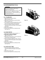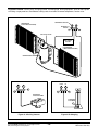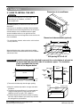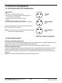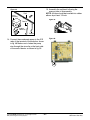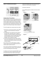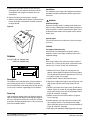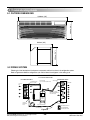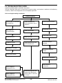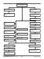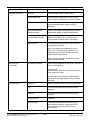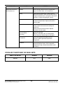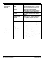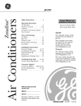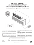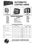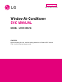
1
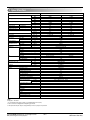
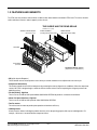
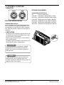
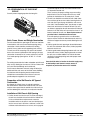
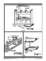
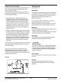
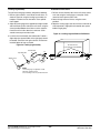
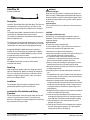
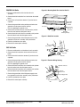
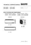
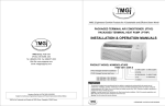
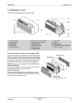
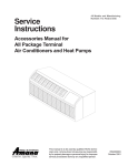
Internal Use Only
http://biz.lgservice.com
Window Air Conditioner
SVC MANUAL
MODEL : LP091CEM-Y8
CAUTION
Before Servicing the unit, read the safety precautions in General SVC manual.
Only for authorized service personnel.
1. Specification
Model
Cooling Capacity
Heating Capacity ( for Heat Pump models)
Electric Heater capacity
Power Input
Running Current
Starting current
Electric Heater Current
EER
COP
Power Supply
Power Factor
Air Flow Rate
Moisture Removal
Sound Level
(SoundPressure,1m)
Refrigerant & Charge
Compressor
Cooling/Heating
Cooling/Heating
Cooling/Heating
Indoor,Max
Outdoor,Max
Indoor,H/M/L
Outdoor,Max
Type
Model
Motor Type
Oil Type
Oil Charge
O.L.P Name
Fan
Type(In/Out)
Motor Type(In/Out)
Motor Output(In/Out)
Power Supply Cable (Power Cord)
Dimensions ( W * H * D)
Net Weight
Tool Code(Chassis)
Features
LP091CEM-Y8
kW
Btu/h.
kW
Btu/h.
kW
Btu/h.
W
A
A
A
W/W
Btu/h.W
W/W
Ø / V / Hz
%
m3/min(CFM)
m3/min(CFM)
l/h
dB(A)±3
dB(A)±3
g(oz)
2.58
8,800
3.1
10,500
800
3.8
14.9
3.11
11.0
1 / 208 / 60
99.9
2.61
8,900
3.5
11,900
810
3.6
15.2
3.11
11.0
1 / 230 / 60
97.8
11(390)
17(600)
1.2
45/-/43
60/59
560
Rotary(Non Tropical)
QA114KCB
PSC
SUNISO 4GSI or NM56M
290
6750U-L018A
cc
Cross Flow Fan
Axial Fan
4 Poles
145
3 * 2.1
1,066*406*505
42*16*19-7/8
41.8(92.2)
YA
Thermistor
O
O
2/2/2
W
No.*mm2
mm
inch
kg(lbs)
Temperature Control
Energy Saver Mode
Prefilter(washable/anti-fungus)
Plasma Filter
Steps, Fan/Cool/Heat
Airflow Direction Control(up&down)
Airflow Direction Control(left&right)
Remote Controller Type
Setting Temperature Range
Cooling
Heating
Auto Operation (Micom Control)
Panel Touch Type
Timer
Air Discharge
Air-Ventilation
Defrost Control
Hot Start
Look
Cabinet Type(Chassis Type)
Special Function
Manual
54˚F ~ 86˚F(12.2˚C ~ 30˚C)
Manual controls
Rear
O
L - Look
Slide In-Out
Electric Heater
Note:
O : Applied, - : No relation
* For circuit breaker rating, please confirm to local standards wherever necessary.
❈ Some of functions are slightly different depending upon models.
❈ The specification may be subject to change without prior notice for purpose of improvement.
Copyright ©2008 LG Electronics. Inc. All right reserved.
Only for training and service purposes
-2-
LGE Internal Use Only
1.2 FEATURES AND BENEFITS
The PTAC has many features, some of which are different than those found on conventional PTAC units. The servicer must be
familiar with these features in order to properly service the unit.
THE SLEEVE AND THE REAR GRILLE
(Available as an option)
VERTICAL AIR DEFLECTOR
(Horizontal Louver)
SLEEVE ASSEMBLY
(Including Aluminum Rear Grille)
REAR GRILLE
(Aluminum Rear Grille)
AIR FILTER
I
N
D
O
O
R
INLET GRILLE
(Air Intake)
EXPANDED METAL GRILLE
(Superior for a performance)
• IIR (Infinite Impulse Response)
The IIR function senses the temperature several times per second and makes micro-adjustments several times per
• Compressor Restart Delay
This feature extends the overall life of compressor by preventing the short-cycling of the air-conditioner. When the compressor
restarts, LG PTAC is designed to give a minimum of three minutes to have a time of equalizing the refrigerant pressures for
optimizing cycling.
• Fan-Only Setting - High/Low
The fan can run at HIGH or LOW speed without COOLING or HEATING to provide air circulation and ventilation.
• Indoor Fan Speed Selections - High/Low
The fan can run at HIGH or LOW speed for either COOLING or HEATING.
• Two Fan motors
The unit has two fan motors to provide quiet operation and maximum efficiency.
• LED Diagnostics
All units have this feature indicating the problem when the unit is not operating properly with easy-to-read diagnostics. For
example, 1 blink every 2 seconds indicates compressor failure.
Copyright ©2008 LG Electronics. Inc. All right reserved.
Only for training and service purposes
-3-
LGE Internal Use Only
• Indoor Filters
The unit uses two indoor filters which slide in and cut easily. The filters may be cleaned by washing and brushing without
removing the front grille.
• Rotary Compressor
The unit uses a rotary compressor for quiet, reliable operation and long life.
• 2 Position Discharge Grille
The discharge grille can provide air flows upward at an angle of 40 off vertical or 15 degree off vertical. The angle is changed
by removing the front grille and 4 screws that fasten the discharge grille to the front grille and rotating the louvers to an
alternate position.
• Indoor Room Freeze Protection
When the unit senses the room temperature falls to less than 40° F the unit activates the fan motor and either the electric
resistance heater or the hydronic heater to prevent pipes or fixtures from freezing. This also overrides front desk control of the
unit mounted or wall mounted controls.
• Door Switch/Occupancy Sensor
The unit is capable of accommodating a field installed door switch and occupancy sensor to operate the energy management
feature. For additional information, refer to the unit operation section.
• Compressor Overload Protection
This feature prevents the damage of the compressor by sensing the indoor tube temperature in heating. If the indoor
temperature is over 130˚ F, the outdoor fan will be switched off and back on when the temperature drops below 120˚ F.
• Outdoor Air Temperature Switchover
This will effectively change the unit from heat pump mode to total electric resistance heat.
• Temperature limits
The unit is programmed to provide both heating and cooling temperature limits by dip switches on control panel from 50˚ F to
90˚ F. Temperature limits help to prevent overheating and overcooling and reduce energy costs.
• Condensate Drain Valve
The unit has a condensate drain valve to prevent water from collecting or freezing in the basepan.
• Quick Heater Recovery
The unit is designed to operate the electric heater to warm the room to the temperature set point as soon as heat pump cycle
is on in heating. This feature has an advantage of reducing the time to reach the set point and improving the temperature
increase for better comfort.
• Reverse Cycle Defrosting - (PTHPs only)
The unit will activate the reverse cycle defrost when the outdoor coil temperature has remained at a cold temperature to form
the ice on the coil.This ice will reduce airflow though the coil and will also reduce the efficiency of unit. The LG PTHP will
employ an active reverse cycle defrost function to melt the ice off the outdoor coil for insuring room comfort conditions and
savings from extended operation.
• High Temperature Heat Pump Operation Protection
The compressor will be switched off to prevent damage when the heat pump is operated in high outdoor temperatures.
• Remote Thermostat Control
Each unit is built to be operated from any standard 4 or 5 wire remote-mounted thermostat, if desired. The unit has a built-in
low voltage power source which can accommodate a large variety of thermostat choices-manual, auto changeover, or
programmable. A remote thermostat can also be added to any installed unit.
• Zone Sensor
Occupants enjoy ultimate comfort with consistent climate control. Attach an optional, inexpensive remote Zone Sensor to
exactly match the functions of the PTAC without disabling any features.
Copyright ©2008 LG Electronics. Inc. All right reserved.
Only for training and service purposes
-4-
LGE Internal Use Only
1.3 CONTROL LOCATIONS
• OPERATION
COOLING ONLY MODEL
ELECTRIC HEATING MODEL
TEMPERATURE CONTROL
Set the Thermostat control to the desired temperature
mark 5 (the mid-point is a good starting position). If the
room temperature is not satisfactory after a reasonable
time, adjust the control to a cooler or warmer setting, as
appropriate.
OPERATION MODE SELECTOR
OFF
Turns air conditioner off.
LOW FAN
Low speed fan operation without cooling.
HIGH FAN High speed fan operation without cooling.
LOW COOL Cooling with the low speed fan operation.
HIGH COOL Cooling with the high speed fan operation.
LOW HEAT Heating with the low speed fan operation.
HIGH HEAT Heating with the high speed fan operation.
• VENTILATION
The ventilation lever is located to the lower left side of the unit.
The ventilation lever must be in the CLOSE position in order
to maintain the best cooling conditions.
When fresh air is necessary in the room, set the ventilation
lever to the OPEN position.
The damper is opened and outdoor air is drawn into the room.
This will reduce the cooling or heating efficiency.
VENT
OPEN
VENT
CLOSE
CAUTION
When the air conditioner has performed a cooling or
heating operation and is turned off or set to the fan
position, wait at least 3 minutes before resetting to the
cooling operation.
NOTE
A slight heat odor may come from the unit when first
switching to HEAT after the cooling season is over.
This odor, caused by fine dust particles on the heater, will
disappear quickly. This is harmless.
Copyright ©2008 LG Electronics. Inc. All right reserved.
Only for training and service purposes
-5-
LGE Internal Use Only
1.4 ADDITIONAL CONTROLS
• REMOVING THE FRONT GRILLE
Additional controls are available after removing the front grille
and option cover of control box.
To remove the front grille, pull out the bottom of front grille and
then lift up.
To replace the front grille, place the tabs over the top of the
unit and push the bottom of front grille until the clips snap into
place.
• ADDITIONAL CONTROLS
The additional controls are located behind the option cover of control box. The standard settings will be in the OFF position.
The authorized service man has to check switches and ensure the switches are in the desired position.
REMOTE ON
ON
ON
ON
ON
OFF
LOCAL OFF
1
2
OFF OFF OFF
3
4
5
Remote/Local
Energy Saver
Temperature Limit 1
Temperature Limit 2 LOCAL
Temperature Limit 3
1
OFF
2
OFF OFF
3
4
OFF
5
• TEMPERATURE LIMITING
Temperature Limiting can save money by limiting the lowest temperature for cooling and the highest temperature for heating.
The temperature limiting is controlled by dip switch #1 - #3.
This temperature limiting is not available with the Remote Wall Thermostat.
Temperature
Limit #1
OFF
ON
OFF
ON
OFF
ON
OFF
ON
Temperature
Limit #2
OFF
OFF
ON
ON
OFF
OFF
ON
ON
Temperature
Limit #3
OFF
OFF
OFF
OFF
ON
ON
ON
ON
Cooling Operation
Lowest Temp. Highest Temp.
54°F (12.2°C) 86°F (30.0°C)
56°F (13.3°C) 86°F (30.0°C)
58°F (14.4°C) 86°F (30.0°C)
60°F (15.5°C) 86°F (30.0°C)
62°F (16.6°C) 86°F (30.0°C)
64°F (17.7°C) 86°F (30.0°C)
66°F (18.9°C) 86°F (30.0°C)
68°F (20.0°C) 86°F (30.0°C)
Copyright ©2008 LG Electronics. Inc. All right reserved.
Only for training and service purposes
-6-
Heating Operation
Lowest Temp. Highest Temp.
54°F (12.2°C) 86°F (30.0°C)
54°F (12.2°C) 84°F (28.9°C)
54°F (12.2°C) 82°F (27.8°C)
54°F (12.2°C) 80°F (26.7°C)
54°F (12.2°C) 78°F (25.5°C)
54°F (12.2°C) 76°F (24.4°C)
54°F (12.2°C) 74°F (23.3°C)
54°F (12.2°C) 72°F (22.2°C)
LGE Internal Use Only
• REMOTE/LOCAL CONTROL
When remote/local switch #1 is on, it allow the unit to operate by the control of Remote Wall Thermostat. The unit control by
knobs are not available.
• ENERGY SAVER
The energy saver switch #2 is on. This switch is set at continuous fan to provide continuous fan operation in cool or heat
modes. When the switch is off the continuous fan allows continuous circulation of room air and make the more balanced
temperature of the room. When the switch is on the fan is on or off with the compressor or with the heater.
• FRONT DESK CONTROL
When the pair wire is connected to the connector LOand LI, the unit can be turned ON or OFF with a switch located at the
Front Desk Control panel. When the front desk switch is ON, the fan operate according to the condition of setting without
working compressor and heater. When the front desk switch is OFF, the unit can operate according to the setting of controls.
Wire # AWG
#22
#20
#18
#16
Maximum Length
600ft(180m)
900ft(270m)
1500ft(450m)
2000ft(610m)
Note:The following figures show
wiring schematics for heat pump
and straight cool units with electric
heat, respectively.
Wiring Schematic for
Remote Heat Pump
LO LI GL GH O
W
Y
R
C
Front Desk Switch
• REMOTE WALL THERMOSTAT
When the wires are connected, the unit will be controlled by a
remote wall thermostat.
The thermostat connections supply the 24 Volt AC. When you
install the digital / electronic thermostat, you must set it to the
24 Volt AC. See the installation Instruction in this manual for
the Remote Wall Thermostat.
Wiring Schematic for
Straight Cool Unit.
24 Volt-N
24 Volt-L
Compressor
Heater
Reversing Valve
High Fan
Low Fan
LO LI GL GH O
W
Y
R
C
(Molex Housing Spec 396-09V)
Copyright ©2008 LG Electronics. Inc. All right reserved.
Only for training and service purposes
-7-
LGE Internal Use Only
2. Disassembly Instructions
— Before the following disassembly, POWER SWITCH is set to OFF and disconnected the power cord.
2.1 MECHANICAL PARTS
2.1.1 FRONT GRILLE
1. Remove the front grille. (See Figure 1)
2. To remove the front grille, pull out the bottom of
the front grille and then lift up.
Re-install the component by referring to the
removal procedure.
3. To replace the front grille, place the tabs over the
top of the unit and push the bottom of front grille
until the clips snap into place.
Figure 1
• This Room Air Conditioner (PTAC) discharges air
from the top of the unit through reversible, 2-position
discharge grille louvers. The unit is shipped from the
factory with the discharge grille louvers at an angle
of 40˚ off vertical. In the alternate position, the
louvers will be at an angle of 15˚ off vertical.
40˚
15˚
To adjust air direction, remove the front grille.
Remove the 4 screws that fasten the discharge grille
to the front grille.
Screws
Flip the discharge grille 180°, then reattach the
discharge grille to the front grille with 4 screws.
Copyright ©2008 LG Electronics. Inc. All right reserved.
Only for training and service purposes
-8-
LGE Internal Use Only
2.1.2 CONTROL BOX
1. Remove the front grille. (Refer to section 2.1.1)
2. Remove the two screws which fasten the control
box. (See Figure 2)
3. Pull the control box from the Air guide.
Figure 2
4. Remove the control box cover. (See Figure 3)
5. Disconnect wire housings on the control box.
Figure 3
6. Pull the control box assembly out from the unit.
(See Figure 4)
7. Re-install the components by referring to the
removal procedure.
Figure 4
Copyright ©2008 LG Electronics. Inc. All right reserved.
Only for training and service purposes
-9-
LGE Internal Use Only
2.2 AIR HANDLING PARTS
2.2.1 ELECTRIC HEATER
(ELECTRIC HEATER MODEL ONLY)
1. Remove the front grille.(Refer to section 2.1.1)
2. Remove the control box assembly.
(Refer to section 2.1.2)
3. Remove the 4 screws which fasten the Evaporator.
(See Figure 5)
Figure 5
4. Remove the top cover assembly, net steel, brace.
(See Figure 6)
Figure 6
5. Remove the 6 screws which fasten the Air-guide.
6. Pull the Air-guide assembly out from the unit.
(See Figure 7)
Figure 7
7. Remove the 2 screws which fasten the electric
heater in the left hand side.
8. Pull the electric heater towards left for a while and
then lift up vertically to disassemble it completely
from Air guide.
Figure 8
Copyright ©2008 LG Electronics. Inc. All right reserved.
Only for training and service purposes
- 10 -
LGE Internal Use Only
2.2.2 CROSS FLOW FAN
1. Remove the front grille. (Refer to section 2.1.1)
2. Remove the control box assembly.
(Refer to section 2.1.2)
3. Remove the Air-Guide Assembly from the unit.
(Refer to section 2.2.1)
4. Loosen the screw on the cross flow fan.
(See Figure 9)
Figure 9
5. Remove the 4 screws which fasten the indoor
motor and the earth wire. (See Figure 10)
6. Remove the supports on both sides.
7. Pull the cross flow fan out from the air-guide.
8. Re-install the components by referring to the
removal procedure.
Figure 10
2.2.3 AXIAL FAN
1. Remove the brace.
2. Remove the 4 screws which fasten the condenser
with the shroud and the basepan. (See Figure 11)
3. Remove the condenser sideways carefully.
Figure 11
4. Remove the clamp which secures the fan with
pliers.(See Figure 12)
5. Remove the axial fan.
6. Re-install the components by referring to the
removal procedure.
Figure 12
Copyright ©2008 LG Electronics. Inc. All right reserved.
Only for training and service purposes
- 11 -
LGE Internal Use Only
2.2.4 SHROUD
1. Remove the axial fan. (Refer to section 2.2.3)
2. Remove the 4 screws which fasten the condenser
with the shroud and the basepan. (See Figure 11)
3. Remove the shroud.
4. Re-install the component by referring to the
removal procedure.
2.3. ELECTRICAL PARTS
2.3.1 OUTDOOR MOTOR
1. Remove the clamp cord and disconnect a wire
housing in control box. (Refer to section 2.1.2)
2. Remove the axial fan. (Refer to section 2.2.3)
3. Remove the 2 screws which fasten the motor.
(See Figure 14)
4. Remove the motor
5. Re-install the component by referring to the
removal procedure, above.
Figure 13
2.3.2 INDOOR MOTOR (Refer to section 2.2.2)
2.3.3 COMPRESSOR
1. Discharge the refrigerant system using a
refrigerant recovery system.
If there is no valve to attach the recovery system,
install one (such as a WATCO A-1) before venting
the refrigerant. Leave the valve in place after
servicing the system.
2. Disconnect the 3 leads from the compressor.
3. After purging the unit completely, unbraze the
suction and discharge tubes at the compressor
connections.
4. Remove the 3 nuts and the 3 washers which
fasten the compressor. (See Figure 15)
5. Remove the compressor.
6. Re-instill the components by referring to the
removal procedure, above.
Figure 14
Figure 15
2.3.4 CAPACITOR
1. Remove the control box. (Refer to section 2.1.2)
2. Remove 1 screw and disconnect the leads which
connected to the box type capacitor.
(See Figure 16)
3. Remove 1 screw and the clamp which fastens the
can-type capacitor.
4. Disconnect all the leads of capacitor terminals.
5. Re-install the components by referring to the
removal procedure, above.
Figure 16
Copyright ©2008 LG Electronics. Inc. All right reserved.
Only for training and service purposes
- 12 -
LGE Internal Use Only
2.3.5 POWER CORD
1. Remove the control box. (Refer to section 2.1.2)
2. Disconnect the grounding screw from the control
box.
3. Disconnect 2 receptacles.
4. Remove a screw which fastens the clip cord.
5. Separate the power cord from the control box.
(See Figure 17)
6. Re-install the component by referring to the
removal procedure, above.
(Use only one ground-marked hole
for ground
connection.)
7. If the supply cord of this appliance is damaged, it
must be replaced by an exact replacement part.
(The special cord means the cord which has the
same specification marked on the supply cord
fitted to the unit.)
Figure 17
2.3.6 P.C.B.
1. Remove the escutcheon.
2. Remove the two knobs.
3. Remove the 2 screws which fasten P.C.B. cover.
4. Disconnect all the leads which connected to the
P.C.B.
5. Remove the two screws which fasten the P.C.B.
board.
6. Re-install the components by referring to the
removal procedure, above.
Figure 18
Copyright ©2008 LG Electronics. Inc. All right reserved.
Only for training and service purposes
- 13 -
LGE Internal Use Only
2.4 REFRIGERATION CYCLE
CAUTION
Discharge the refrigerant system using a
refrigerant recovery system.
If there is no valve to attach the recovery system,
install one (such as a WATCO A-1) before
venting the refrigerant. Leave the valve in place
after servicing the system.
2.4.1 CONDENSER
1. Remove the brace and the shroud.
(Refer to section 2.2.2)
2. Remove the 4 screws which fasten the shroud.
(Refer to section 2.2.2)
3. Push forward the shroud and remove the 2 screws
which fasten the condenser with the basepan.
4. After discharging the refrigerant completely,
unbraze the interconnecting tube at the condenser
connections.
5. Remove the condenser.
6. Re-install the components by referring to notes.
(See Figure 19)
Figure 19
2.4.2 EVAPORATOR
1. Remove the front grille. (Refer to section 2.1.1)
2. Discharge the refrigerant completely.
3. Remove the control box assembly.
(Refer to section 2.1.2)
4. Remove the 4 screws which fasten the evaporator
at the left side and the right side.
5. Move the evaporator sideward carefully and then
unbraze the interconnecting tube at the evaporator
connectors.
6. Remove the evaporator.
7. Re-install the components by referring to notes.
(See Figure 20)
Figure 20
2.4.3 CAPILLARY TUBE
1. After discharging the refrigerant completely,
unbraze the interconnecting tube at the capillary
tube.
2. Remove the capillary tube.
3. Re-install the components by referring to notes.
Copyright ©2008 LG Electronics. Inc. All right reserved.
Only for training and service purposes
- 14 -
LGE Internal Use Only
NOTES
— Replacement of the refrigeration cycle.
1. When replacing the refrigeration cycle, be sure to
discharge the refrigerant system using a
refrigerant recovery system.
If there is no valve to attach the recovery system,
install one (such as a WATCO A-1) before venting
the refrigerant. Leave the valve in place after
servicing the system.
2. After discharging the unit completely, remove the
desired component, and unbraze the pinch-off
tubes.
3. Solder service valves into the pinch-off tube ports,
leaving the valves open.
4. Solder the pinch-off tubes with service valves.
5. Evacuate as follows.
1) Connect the vacuum pump, as illustrated
Figure 21 A.
2) Start the vacuum pump, slowly open manifold
valves A and B with two full turns
counterclockwise and leave the valves closed.
The vacuum pump is now pulling through valves
A and B up to valve C by means of the manifold
and entire system.
CAUTION
If high vacuum equipment is used, just crack
valves A and B for a few minutes, then open
slowly with the two full turns counterclockwise.
This will keep oil from foaming and being
drawn into the vacuum pump.
3) Operate the vacuum pump for 20 to 30 minutes,
until 600 microns of vacuum are obtained. Close
valves A and B, and observe the vacuum gauge
for a few minutes. A rise in pressure would
indicate a possible leak or moisture remaining in
the system. With valves A and B closed, stop
the vacuum pump.
4) Remove the hose from the vacuum pump and
place it on the charging cylinder. See Figure 21 B.
Open valve C.
Discharge the line at the manifold connection.
5) The system is now ready for final charging.
Copyright ©2008 LG Electronics. Inc. All right reserved.
Only for training and service purposes
- 15 -
6. Recharge as follows :
1) Refrigeration cycle systems are charged from the
high-side. If the total charge cannot be put
in the high-side, the balance will be put in the
suction line through the access valve which you
installed as the system was opened.
2) Connect the charging cylinder as shown in Figure 21
B.
With valve C open, discharge the hose at the
manifold connection.
3) Open valve A and allow the proper charge to
enter the system. Valve B is still closed.
4) If more charge is required, the high-side will not
take it. Close valve A.
5) With the unit running, open valve B and add the
balance of the charge.
a. Do not add the liquid refrigerant to the lowside.
b. Watch the low-side gauge; allow pressure to
rise to 30 lbs.
c. Turn off valve B and allow pressure to drop.
d. Repeat steps B and C until the balance of the
charge is in the system.
6) When satisfied the unit is operating correctly,
use the pinch-off tool with the unit still running
and clamp on to the pinch-off tube. Using a tube
cutter, cut the pinch-off tube about 2 inches from
the pinch-off tool. Use sil-fos solder and solder
pinch-off tube closed. Turn off the unit, allow it to
set for a while, and then test the leakage of the
pinch-off connection.
LGE Internal Use Only
Equipment needed: Vacuum pump, charging cylinder, manifold gauge, brazing equipment. pinch-off tool capable
of making a vapor-proof seal, leak detector, tubing cutter, hand tools to remove components, service valve.
COMPOUND GAUGE
CONDENSER
(HIGH PRESSURE SIDE)
MANIFOLD
GAUGE
A
B
CAPILLARY TUBE
SEE INSETS
BELOW
EVAPORATOR
(LOW PRESSURE SIDE)
COMPRESSOR
LOW
HI
A
B
B
A
EXTERNAL
VACUUM PUMP
CHARGING
CYLINDER
C
Figure 21 A-Pulling Vacuum
Copyright ©2008 LG Electronics. Inc. All right reserved.
Only for training and service purposes
Figure 21 B-Charging
- 16 -
LGE Internal Use Only
3. Installation
Dimension of air conditioner
3.1 HOW TO INSTALL THE UNIT
CAUTION
1,066 mm
(42")
• There are sharp edges that can cause serious cuts.
• When lifting the air conditioner, it is HEAVY.
Use 2 people to lift.
For existing sleeve, you should measure the wall sleeve
dimensions.
Install the new air conditioner according to these installation
instructions to achieve the best performence. All wall sleeves
used to mount the new air conditioner must be in good
structural condition and have a rear grille that securely
attaches to the sleeve or the flange of the sleeve to secure the
new air conditioner.
406 mm
(16")
349 mm
(13 3/4")
505 mm
(20")
Dimension of sleeve assembly (optional)
• To avoid vibration and noise, make sure the unit is installed
securely and firmly.
42"
1/2" SQ. HOLE (2 REQ'D.)
13
"
-3/4
2-3/4"
1-1/2" TYP
1/2"
16"
5-5/8"
4"
When installing the sleeve, make certain there is nothing
within 20" of the back that would interfere with heat radiation
and exhaust air flow.
6"
36"
21"
1/2" DIA.
HOLE (3 REQ'D.)
Wall opening 16-1/4"x42-1/4"
Recommended Insulation strip must be attached to prevent the re-circulation of exhaust air
to inward side from the either side of condenser space. The insulation
strip is provided with the box.
Refer to the diagram below.
GRILLE
INSULATION
WALL
COOLED
AIR
13-3/4"
SLEEVE
HEAT
RADIATION
TOP VIEW
INTAKE
AIR
1/4" Bubble
of the level
42"
FRONT
GRILE
WALL
Over 20"
1) Take out the insulation strip from the upper packing.
2) Attach the insulation strip onto the rear upper side of the
wall sleeve.
3) To improve unit energy efficiency, it is recommended the
change of outside grille for an unit protection and an
addition of a plastic rear grille. (This is optional.)
4) Insulation strip prevents the exhaust air from re-entering
from either side of condenser space which may decrease
the cooling efficiency of condenser.
Copyright ©2008 LG Electronics. Inc. All right reserved.
Only for training and service purposes
- 17 -
280 mm
(11")
Front
Insulation Strip
Sleeve
Rear
LGE Internal Use Only
3.2 WALL SLEEVE INSTALLATION
3.2.1 Wall Case Installation Data
For new construction, early planning with the architect
is necessary. Unit location, electrical connection
locations, and wall openings of the proper dimensions
are essential to avoid the necessity of rework, fillers,
framing, moving electrical outlets, and other expensive
modifications.
General
Generally, units are installed 3" to 5" above the floor
(flush to finished floor installation is possible) as near to
the center of the room as possible; underneath a
window or a glass panel is typical. Normal installation of
the wall case allows installation flexibility; from flush
with the finished interior wall to a minimum of 1/4" of the
wall case extending beyond the finished exterior of the
building.
Special consideration must be given to installations
where the wall case does not extend a minimum of 1/4"
beyond the finished exterior wall.
For existing construction it is important that carpentry,
masonry and electrical work be performed by
competent, qualified personnel. Since installations in
existing construction may involve removal of
building material from the structure, locating the
wall case must be done correctly.
Regardless of the installation, there are several things
to consider when selecting a location for installing the
unit. For instance, drapery location could interfere with
air discharge, and placement of furniture may have an
impact on the performance of the unit. The following
information is intended to minimize installation
problems and assure you of trouble-free installation.
Refer to page 17 for required wall opening dimensions.
Minimum recommended interior and exterior case
projection for standard wall thicknesses are shown in
the drawings in this manual. The case may be installed
flush with the finished indoor wall.
Mounting an outdoor grille or louver section to the
building face may cause a space between the outdoor
coil and the louver section. Air splitters, aligned with the
ends of the outdoor coil, must be installed between the
outdoor coil inlet and outlet air streams. Gaps between
the outdoor coil and the louver section may allow
condenser air recirculation and affect the operation of
the unit.
The wall case should be level from side to side
and from level to 1/4 bubble tilt to the outdoors.
The condensate disposal system in the unit is
designed to dissipate the condensate water
generated during cooling operation in
accordance with ARI standards and actually
uses this water for maximum unit efficiency. A
level unit will also insure proper performance of
the Internal Condensate Removal (ICR) system
optional on heat pump units.
Copyright ©2008 LG Electronics. Inc. All right reserved.
Only for training and service purposes
- 18 -
LGE Internal Use Only
3.2.2 PREPARATION OF THE FRONT
GRILLE
Carefully remove shipping tape from the front grille.
Shipping Tape
Brick, Frame, Stucco and Shingle Construction
For new construction, the opening for the wall case should be
framed and the wall case inserted into the opening during
construction. Lintels should be used when the building
material is heavy and is not self supporting (such as brick).
The wall case will fit an opening of six courses of standard
brick or five courses of jumbo brick. Wall framing in this type
construction is normally on 16" centers and the wall case will
fit a framed opening spanning three 16" O.C. 2" x 4" stud
spaces.
For existing construction the indoor and outdoor wall will need
to be cut out, allowing for clearances of 1/8" on all sides of the
wall case. Work should begin on the inside wall.
Cut the correct dimensions and mark (using drill holes) the
outside wall from each corner of the inside cutout. Studding
that interferes with the opening must be removed and a
suitable frame constructed to secure the wall case and
provide adequate support for case and chassis.
The outside edge of the wall case should extend at least
1/4" beyond the outside wall.
This is necessary for proper caulking, to prevent sealing
thedrain holes in the rear flange of the wall case, and to
facilitate the installation of an accessory drain, if used.
2. The wall case should be secured to the wall at both sides.
Use a minimum of two screws or other fastening device on
each side. See Figure 23 page 20. Mark the wall case on
each side 2" from the bottom and 2" from the top at a point
where basic wall structure is located. Drill wall case and
use fasteners appropriate for wall construction. All holes for
fasteners in the side of the wall case must be at least 2" up
from the bottom of the wall case. Never locate screws or
put other holes in the bottom of the wall case.
If the wall opening is greater than the case dimensions,
spacers must be used on the sides between the wall case
and the wall support structure to prevent distorting the wall
case.
3. Caulk or gasket the entire opening on the outside between
the wall case and exterior wall surface (4 sides) to provide
total water and air seal.
4. Caulk or gasket room-side opening between wall case and
interior wall surface (4 sides). Opening beneath or around
the wall case can allow outdoor air to leak into the room
resulting in increased operating costs and improper room
temperature control.
Care should be taken in location of electrical supply entry
in relationship to wall sleeve to assure access to
receptacle or junction box once unit is installed.
Preparation of the Wall Case for All Types of
Construction
As shipped, the LG wall sleeve is ready for installation.
Do not remove the stiffener from inside the wall case or the
weather closure panel from the outside face of the wall case
until the outdoor grille and chassis are ready to be installed.
Installation of Wall Case in Wall Opening
1. Position the wall case into the wall. The room side edge of
the wall case should be at least flush with the finished wall
for line cord installations and permanent connection
installations when no sub-base is used, and should project
into the room at least 2-3/8" when a sub-base is used. If the
minimum exterior dimensions are not met, refer to page 20.
Copyright ©2008 LG Electronics. Inc. All right reserved.
Only for training and service purposes
- 19 -
LGE Internal Use Only
Copyright ©2008 LG Electronics. Inc. All right reserved.
Only for training and service purposes
- 20 -
LGE Internal Use Only
Copyright ©2008 LG Electronics. Inc. All right reserved.
Only for training and service purposes
- 21 -
LGE Internal Use Only
WALL RECEPTACLE
(BY OTHERS)
2" MIN.
CAULK*
POWER SUPPLY
CONDUIT
OUTDOOR
GRILLE
STEEL LINTEL
CAULK*
1/4"
MIN.
WALL CASE
MOUNTING SCREWS
BY INSTALLER
20-7/8" (RAB71)
21"
(RAB77)
RAB71 13-3/4"
RAB77 13-7/8"
*Caulk around perimeter of wall case all four sides
where it joins the building - Interior and Exterior.
FINISHED FLOOR
OR TOP OF
CARPET
CAULK*
ROOM
CABINET
CAULK*
Cord Set Connected
FINISHED FLOOR
OR TOP OF
CARPET
3" MIN.
5" MAX.
FRAME AND BRICK VENEER INSTALLATION
WALL SECTION – DETAILED SIDE VIEW
SIDE CHANNEL
POWER SUPPLY CONDUIT
(ALTERNATE ENTRY)
2" MIN.
MOUNTING SCREWS
BY INSTALLER
WALL CASE
3-11/16"
CAULK*
SUB-BASE
(RAK204)
1-5/16"
ROOM
CABINET
CAULK*
2-3/8"
LINTEL
Sub-Base Connected
*Caulk around
perimeter of wall
case all four
sides where it
joins the building
- Interior and
Exterior.
OUTDOOR
GRILLE
CAULK*
1/4"
3.2.3 UNIT INSTALLATION
1. Remove the shipping screw from the ventilation door.
(See Figure 24)
Figure 24
2. Remove the front gille by pulling it out at the bottom to
release it, then lift it up along the unit top front.
(See Figure 25)
Figure 25
3. Slide the unit into the wall sleeve and secure with 6 screws
through the unit flange holes. (See Figure 26)
Figure 26
4. Reinstall the front grille by hooking the top over the unit top,
then pushing it in at the bottom. (See Figure 27)
Figure 27
Copyright ©2008 LG Electronics. Inc. All right reserved.
Only for training and service purposes
- 22 -
LGE Internal Use Only
3.3 ELECTRICAL REQUIREMENTS
3.3.1 ELECTRICAL DATA (FOR 230/208V MODEL)
CAUTION
1. Do not use an extension cord with this unit.
2. When the unit is in the OFF position, the power supply to the
electrical controls is still energized.
3. Disconnect the power to the unit before servicing
the unit.
4. Remove the power cord from the wall receptacle.
5. Remove or turn off the protective device (fuses or circuit breaker).
Tandem
15 A
Perpendicular
20 A
Wirings including installation of the receptacle must comply with the
NEC and local codes, local regulations.
FUSE- Use a time-delay fuse or circuit breaker. Refer to the nameplate
for proper power supply requirements.
Large Tandem
30 A
230/208 volt receptacle configuration
3.3.2 ELECTRICAL SAFETY
IMPORTANT GROUNDING INSTRUCTIONS
The air conditioner has a three-prong grounding plug on its power supply cord which must be plugged into properly grounded
three-prong wall receptacle for your protection against possible shock hazard.
FUSE – Use a time-delay fuse or circuit breaker. Refer to the nameplate for proper power supply requirements.
208, 230, and 208/230 VOLT UNITS
These units are equipped with a three-prong grounding plug on the power supply cord which must be plugged into a matching
properly grounded three-prong wall receptacle for your protection against possible shock hazard. If such an outlet is not
present, one must be installed by a qualified electrician in accordance with the National Electrical Code and local codes and
ordinances.
NOTE: DO NOT USE AN EXTENSION CORD on 208, 230, and 208/230 Volt units.
Copyright ©2008 LG Electronics. Inc. All right reserved.
Only for training and service purposes
- 23 -
LGE Internal Use Only
4. Field Installed Accessories
Note: The installation and servicing of this equipment must be performed by qualified,
experienced technicians
NOTICE:
Warnings and Cautions appear at appropriate sections throughout this manual. Read these carefully.
WARNING - Indicates a potentially hazardous situation which, if not avoided, could result in death or serious injury.
CAUTION - Indicates a potentially hazardous situation which, if not avoided, may result in minor or moderate injury. It may
also be used to alert against unsafe practices.
CAUTION –Indicates a situation that may result in equipment or property-damage-only accidents.
Control Panel Key Lock
Part No: AYCP101
2. Remove existing door assembly by lifting door halfway and
using both hands, bow door just enough for door hinge pins
to slide out of mating holes. (Figure 29)
Figure 29 - Door Removal
Description
The Key Lock kit prevents tampering of the controls used to
set temperatures and heating or cooling functions.
Receiving
Upon receipt of the product, inspect the shipping carton for
signs of visible damage. Report any damage or shortage to
the carrier and note it on the delivery receipt. Unit must be
stored in its original shipping carton in a dry, secure place
prior to its installation and use.
Installation
The installation and servicing of the equipment referred to in
this booklet should be performed by qualified, experienced
technicians.
1. Remove front from unit by pulling bottom out and then
lifting upward. (Figure 28)
3. Install the new door assembly with the key lock by bowing
the door with both hands and aligning the door hinge pins
with their bracket in the front. (Figure 30)
Important Note:
Personal Risk Hazard Underwriter’s Laboratories Inc. listed.
For institutional use only where supervisory monitoring is
available.
Any other use may increase the risk of personal injury or
property damage.
Figure 30 - New Door Installation
Figure 28 - Remove Front
Door
Hinge Pins
(Each Side)
Front
Copyright ©2008 LG Electronics. Inc. All right reserved.
Only for training and service purposes
- 24 -
Brackets
(Each Side)
LGE Internal Use Only
Condensate Disposal Pump Kit
Installation
1. Remove front plastic cover by rotating bottom outward and
then lifting up and out from chassis.
Part No: AYSB2101
2. Unplug and remove the PTAC chassis from the wallsleeve.
Movethe chassis where the front and back of the chassis
can be easily accessed.
Description
The internal condensate pump serves as a means for
disposing of condensate generated during heat pump
operation by transferring it to the indoor coil. The warm coil
surface and the warm room air help in evaporation of the
condensate while adding humidity to the room.
As with any equipment of this type, the addition of this kit will
decrease the effective heating capacity of the unit. This kit is
not intended for use in seacoast or corrosive environments.
NOTE:
Under extreme high humidity conditions, the internal
condensate pump may not be able to dispose of all the
condensate produced, and condensate would then drip from
the outside of the wall sleeve. If this condensation is
unacceptable, then a drain system (including factory
approved drain kit for the wall sleeve) should be installed.
3. Remove the wire junction box cover by removing four
screws and lifting up as shown in figure 31.
Figure 31
4. Remove and set aside the air discharge screen by
unscrewing the 5 screws on the top.
5. Remove the one screws holding the control board cover as
shown figure 32.
Remove the cover by lifting it up so its free from its hinges,
and put aside.
Receiving
Upon receipt of the product, inspect the shipping carton for
signs of visible damage. Report any damage or shortage to
the carrier and note it on the delivery receipt. Unit must be
stored in its original shipping carton in a dry, secure place
prior to its installation and use.
Figure 32
Installation
The installation and servicing of the equipment referred to in
this booklet should be performed by qualified, experienced
technicians.
WARNING
Hazardous Voltage!
Disconnect all electric power, including remote disconnects
before servicing. Follow proper lockout/tagout procedures to
ensure the power can not be inadvertently energized. Failure
to disconnect power before servicing could result in death or
serious injury.
6. Unplug the electric heater connecter located inside the wire
junction box.
Important Note:
The unit OFF switch does not disconnect all electrical power
to this unit.
Copyright ©2008 LG Electronics. Inc. All right reserved.
Only for training and service purposes
- 25 -
LGE Internal Use Only
7. Remove the screw that attaches the electric heater wire to
the side of the indoor fan housing.
11. Install tube #1 and tube #2 (ref. fig. 38) on the pump
assembly using the rubber elbows as shown in fig. 35.
8. Remove the 3 screws which fasten the top cover assembly.
Figure 35
Figure 33
9. Position water spraying plastic tube into the electric heater
cover. Make sure that the three pairs(total of six) of plastic
tongues snap into the corresponding metal slots of the
heater frame as shown in fig. 34. Then install one of the
three rubber elbows(ref. fig. 38) at the inlet of the spraying
tube and through the rubber grommet.
12. Position pump assembly to the basepan as shown in fig.
36 and fasten the pump bracket to the basepan using the
three screws provided.
Figure 36
Figure 34
10. Place the top cover assembly back into the unit.
13. Insert tube #2 of the pump assembly through the plastic
grommet of the sheet metal partition as shown in fig. 37.
Then connect the end of tube #2 to the plastic elbow
coming out of the inlet of the spraying tube.
Figure 37
Copyright ©2008 LG Electronics. Inc. All right reserved.
Only for training and service purposes
- 26 -
LGE Internal Use Only
15. Assembly the unit back following the
reverse order of disassembly.
NOTE: All tube should be inserted into rubber
elbows by at least 1/2 inch
Figure 38
Spraying
Tube
Pump
assembly
Figure 39
Tube #1
Rubber
elbows(3)
Tube #2
14. Connect the condensate pump to the ICR
relay of the terminal of the board as shown
in fig. 40 Make sure to fasten the pump
wire through the wire clip on the back side
of the control barrier as shown in fig. 39
Copyright ©2008 LG Electronics. Inc. All right reserved.
Only for training and service purposes
- 27 -
Figure 40
LGE Internal Use Only
Architecture Grille Aluminum - Single
Pack
Note:
A baffle kit must not be used with a stamped aluminum grille
on any PTAC installation.
Part No: AYAGALA01
Stamped Aluminum Grille
Stamped Aluminum Grille
1. Prepare the wall sleeve for installation of the grille by
removing the cardboard stiffener and rear enclosure panel
from the sleeve. These items may be removed from inside
of the building.
Note:
The sleeve stiffener must be taken out before the rear sleeve
enclosure panel can be removed from the sleeve.
Architecture Grille
Description
Outdoor grilles are attached to the wall sleeve and exposed to
the exterior wall. The grilles are an industry standard size of
42" x 16".
Receiving
Upon receipt of the product, inspect the shipping carton for
signs of visible damage. Report any damage or shortage to
the carrier and note it on the delivery receipt. The unit must
be stored in its original shipping carton in a dry, secure place
prior to its installation and use.
Installation
The installation and servicing of the equipment referred to in
this booklet should be performed by qualified, experienced
technicians.
Hazardous Voltage!
Disconnect all electric power, including remote disconnects
before servicing. Follow proper lockout/tagout procedures to
ensure the power can not be inadvertently energized. Failure
to disconnect power before servicing could result in death or
serious injury.
Copyright ©2008 LG Electronics. Inc. All right reserved.
Only for training and service purposes
3. Turn the grille so it can be removed through the rear sleeve
opening.
4. Install the stamped aluminum grille by aligning the guide
pins located in the lower right and left hand corners of the
grille with the corresponding holes in the rear of the wall
sleeve.
5. Secure the grille by threading each of the screws into the
plastic grommets.
6. Remove the wire handle (not shown in the picture) from the
center of the grille prior to installing the chassis into the
sleeve.
Note:
Be sure to keep a firm grip on wire handle and grille to
prevent it from dropping and/or causing possible injury or
property damage.
WARNING
Important Note:
The unit OFF switch does not disconnect all electrical power
to this unit.
2. Prepare the stamped aluminum grille for installation on the
sleeve by inserting the six (6) plastic grommets into the
square holes located near the outer edges of all four sides
of the grille. With the grille positioned so the flanges of all
four sides are in the up position, insert the grommets so the
square end protrudes through the grille in the opposite
direction from the flanges.
Architectural Grille
1. Remove the cardboard sleeve stiffener and the rear
enclosure of the sleeve as described in Step 1 of the
stamped aluminum grille instructions.
2. Turn the grille so it can be removed through the rear sleeve
opening.
3. Install the grille by aligning the four screws supplied to their
corresonding holes in the architectural grille.
- 28 -
LGE Internal Use Only
4. Secure the grille to the sleeve by tightening the four screws
to their corresponding holes in the grille.
5. Remove the wire handle after the installation is complete.
Note:
The stamped aluminum grille includes 6 screws, washers,
nuts, and plastic grommets. The architectural grille includes 4
screws.
Receiving
Upon receipt of the product, inspect the shipping carton for
signs of visible damage. Report any damage or shortage to
the carrier and note it on the delivery receipt. The product
must be stored in its original shipping carton in a dry, secure
place prior to its installation and use.
Installation
The installation and servicing of the equipment referred to in
this booklet should be performed by qualified, experienced
technicians.
Condensate Drain kit
Part No: AYDR101
Figure 41 – Components of Drain Kits
DRAIN FITTING
PLATE B
BLANK-OFF
PLATE C
BLANK-OFF
PLATE C
GASKETS A
Description
Condensate water will drain from the chassis into the sleeve
during normal heat pump operation. This can also occur
during times of high humidity when in cooling operation.
Install either the outdoor or indoor drain kit components to
control the condensate water where normal drainage from the
wall sleeve is not possible or undesirable. See Figure 35 for
all components of the drain kit.
1/2" DRAIN FITTING
MTG. SCREWS
MTG. SCREWS
BLANK-OFF
PLATE D
GASKET E FOR
PLATE D
WARNING
Hazardous Voltage!
Disconnect all electric power, including remote disconnects
before servicing. Follow proper lockout/ tagout procedures to
ensure the power can not be inadvertently energized. Failure
to disconnect power before servicing could result in death or
serious injury.
Important Note:
The unit OFF switch does not disconnect all electrical power
to this unit.
Copyright ©2008 LG Electronics. Inc. All right reserved.
Only for training and service purposes
Drain Installation
Note:
The optional drain kit serves only as a link between the unit
and field-supplied condensate drain system.
Installing the kit without connecting it to a drainage system
will result in inadequate condensate removal, possible
leakage and corrosion.
Algaecide: Some algaecide products may cause damage to
the unit basepan and therefore should not be used. Contact
your sales representative when considering the use of a
commercial algaecide. See Figure 41 for components of the
drain kit.
- 29 -
LGE Internal Use Only
contact the front edge of sleeve. Secure the chassis to the
wall sleeve on each side with screws provided.
Figure 42 – Outdoor Drain Kit Installation
Re-install the cabinet front.
DRAIN FITTING
PLATE B
1/2" DRAIN
FITTING
See the following pages for installation instructions of indoor
drain kit.
BLANK-OFF
PLATE C
Figure 43
Figure 44
GASKETS A
MTG. SCREWS
Outdoor Drain Kit Installation
PLATE "B"
Before installing the wall sleeve louvered condenser grille, it
must be determined if the optional outdoor wall sleeve drain
kit is to be installed. The drain kit will allow the condensate
from the outdoor and indoor coils to be routed to a suitable
area. The drain kit can be installed so the condensate can be
drained from the right or left hand side of the wall sleeve. See
Figure 42. See local codes for proper condensate disposal.
G
DRAIN FITTING
Figure 45
To install the outdoor drain components proceed as follows:
1. Remove the rear enclosure panel and the sleeve stiffener.
These items may be removed from the inside of the
building.
2. The drain fitting can be installed on the left or right hand
side of the sleeve. (Illustration will be for a right hand
installation.) Insert the drain fitting in the opening of gasket
A and hole of plate B. Secure this assembly to the rear of
the sleeve with two sheet metal screws into holes G
provided in sleeve. See Figures 43 and 44.
BLANK-OFF PLATE
SHEET METAL SCREWS
Figure 46
3. Locate the other gasket A on the back of blank off plate C
and secure the assembly to the left rear of wall sleeve with
sheet metal screws provided. See Figure 45 for finished left
hand side installation.
If the unit chassis is to be installed right away, install the
condenser grille to wall sleeve with hardware provided. See
condenser grille installation instructions.
See Detail A
Sleeve overflow port
Do not close up this port
Gasket (2)
Blank-off Plate (2)
(4) Mounting Screws
If the unit chassis will not be installed right away, replace the
rear enclosure panel in the wall sleeve. This will help protect
the inside of the building from weather damage.
Gasket
Wall Sleeve Bottom
Cover
Plate
1/2" Outdoor Drain Fitting
Detail A
MTG. Screws (2)
If a subbase is used, be sure the right hand subbase cover is
removed before the chassis is installed in the sleeve. Slide
the chassis into the wall sleeve until the chassis flanges
Copyright ©2008 LG Electronics. Inc. All right reserved.
Only for training and service purposes
- 30 -
LGE Internal Use Only
Indoor Drain Kit Installation
Leveling Legs
The internal drain is installed on the bottom of the wall sleeve
when it is required to drain the condensate into a drain
system inside of the building.
The components of the wall sleeve drain kit are shown in
Detail A. Use components C (2), D, E, mounting screws (6)
and the Outdoor drain fitting.
Part No: AYLL101
1. The components D, E, and drain fitting of the kit are
mounted on the bottom of the wall sleeve prior to the
installation of the sleeve. It may be located in a feasible
area on the bottom of the sleeve which is inside of the
room except when a subbase is used. When a subbase is
installed, the drain may be a minimum of 3 1/2 " from the
front flange of the wall sleeve. The minimum clearance
should provide adequate clearance for the subbase, see
Figures 46 and 47.
2. Cut out the template in the lower right hand corner of these
instructions to locate the field drilled holes. (Two to mount
the plate and one for the Outdoor drain fitting). See Detail
A on how the components have to be installed after the
holes are drilled in the bottom of the wall sleeve. If the
drain fitting is not connected to an indoor drainage system
immediately after the wall sleeve is installed, it must be
plugged with a cork to prevent indoor water damage in
case it rains.
An indoor tube or hose (furnished by others) must be installed
on the drain fitting and interconnected to the drain system
inside of the building.
Install the two blank-off plates C and gaskets A on the
outdoor portion of the wall sleeve as shown in Figure 46.
These components may be installed after the sleeve is
secured in the wall opening just prior to the installation of the
condenser grille and chassis.
Figure 47
Description
Leveling legs are designed to provide extra front support and
leveling of the wall sleeve. Two leg assemblies are required
per unit and are provided in each kit. Four screws are also
provided with each kit for attachment to the wall
sleeve. See Figure 48.
The leveling legs must be installed before the chassis is
installed, but after the wall sleeve is in place.
Holes must be drilled in each side of the wall sleeve, below
the duct package holes, for attachment to the wall sleeve.
Receiving
• Compare kit identification number with sales order to ensure
that the correct kit has been received.
• Inspect the leveling legs for shipping damage. File damage
claims with the delivering carrier immediately.
Installation
The installation and servicing of this equipment should be
performed by qualified, experienced technicians.
WARNING
Hazardous Voltage!
Disconnect all electric power, including remote disconnects
before servicing. Follow proper lockout/tagout procedures
to ensure the power can not be inadvertently energized.
Failure to disconnect power before servicing could result in
death or serious injury.
Important Note:
The unit OFF switch does not disconnect all electrical power
to this unit.
Checklist
The following is an abbreviated guide to leveling leg
installation. Refer to appropriate areas for more detailed
information.
Copyright ©2008 LG Electronics. Inc. All right reserved.
Only for training and service purposes
- 31 -
LGE Internal Use Only
Leveling Leg Assembly
Installation on Wall Sleeve
To install the leveling leg assembly, complete the following:
1. Drill four 1/8-inch diameter holes in the wall sleeve, two on
each side, using the leveling legs as a template. Caulk
around screws to prevent water leaks.
1. Drill two 1/8-inch holes in each side of the wall sleeve, as
shown in Figure 48, using the leveling leg assembly as a
template. Locations near the front of the sleeve provide
more support.
2. Attach the legs to the wall sleeve, using the screws
provided.
2. Adjust the leveling legs to the approximate height needed
and install them on either side of the wall sleeve, using the
screws provided. Bottom of wall sleeve can be anywhere
from three to five inches above the screw base. Caulk
around screws to prevent water leaks.
3. Adjust the leveling legs to level the wall sleeve from side to
side and provide a slight pitch to the outside (one-quarter
bubble in sight glass).
Figure 49 - Leveling Leg Installation on Wall Sleeve
3. Level the sleeve horizontally from side-to-side. Provide a
slight slope (one-quarter bubble in the sight glass) toward
the outside. Check the level again after the unit has been
installed. Adjust the legs as needed.
Figure 48 - Leveling Leg Assembly
Leveler Bracket
1/8" Diameter holes
(four required per unit field-drilled)
1/2"
Speed Grip Nut
1"
Adjuster Screw
1/4"
NOTES:
1. Two leveling legs are supplied in each kit.
2. One kit is required per unit.
3. Four mounting screws are provided in each kit.
Copyright ©2008 LG Electronics. Inc. All right reserved.
Only for training and service purposes
- 32 -
LGE Internal Use Only
Hard Wire Kit
WARNING
Hazardous Voltage!
Disconnect all electric power, including remote disconnects
before servicing. Follow proper lockout/tagout procedures to
ensure the power can not be inadvertently energized. Failure
to disconnect power before servicing could result in death or
serious injury.
Part No: AYAGALA01
Description
Hard Wire Junction Box (Direct Wire Sub-Base) The hard wire
junction box kit is used to hard wire the unit when it is not
desirable to use the standard unit subbase or the unit power
cord.
The junction box provides a protected enclosure for electrical
connections as required by some electrical codes.
The hard wire junction box is intended to be mounted on the
floor or the adjacent wall.
The junction box is furnished with approximately 2-1/2 feet of
1/2-inch flexible steel conduit and a metal box for securing the
conduit to the unit cabinet at the incoming power opening.
An optional 230/208V or 265V power switch assembly is
available for use with the hard wire junction box or subbase.
The switch provides a POWER ON/OFF function at the unit
as required by some electrical codes.
A replacement junction box cover plate is provided with each
switch kit.
For additional information, refer to the Power Switch
Installation Instructions.
Receiving
Upon receipt of the product, inspect the shipping carton for
signs of visible damage. Report any damage or shortage to
the carrier and note it on the delivery receipt. Unit must be
stored in its original shipping carton in a dry, secure place
prior to its installation and use.
Installation
The installation and servicing of this equipment should
performed by qualified, experienced technicians.
Junction Box Kit Installation and Wiring
Procedure
EIectrical connections at the unit must be made after the unit
chassis is installed in the wall sleeve. The installer must
determine and supply the mounting components for attaching
the junction box to the wall or door.
Copyright ©2008 LG Electronics. Inc. All right reserved.
Only for training and service purposes
Important Note:
The unit OFF switch does not disconnect all electrical power
to this unit.
CAUTION
Use Copper Conductors Only!
Unit terminals are not designed to accept other types of
conductors. Failure to use copper conductors may result in
equipment damage.
Important Note:
All wiring must comply with applicable
local and national codes. Types and location of disconnect
switches must comply with all applicable codes.
1. Remove the cover plate from the junction box
2. Mount the junction box to the wall or floor within 28 inches (711
mm) of the lower right corner of the wall sleeve.
3. If a disconnect switch is to be used, make electrical
connections to it and mount the switch in the junction box.
Refer to the Power Switch Installation Instructions.
4. Remove control panel assembly by removing the two screws
holding control panel in place. Rotate the panel forward.
5. Disconnect the power cord leads from all electrical connections
including the ground wire.
6. Remove the power cord clamp and the power cord from the
unit.
7. For 208/230-volt units, remove and discard the white lead from
the wire assembly. For 265-volt units, remove and discard the
red lead from the wire assembly.
8. Remove the retaining ring from the threaded portion of the
straight conduit clamp. Insert the three wires into the metal box
through one of the two openings in the box. Replace the hole
cover grommet into the unused hole to prevent objects from
entering the box.
9. Replace the retaining ring back on the conduit clamp inside the
metal box and tighten the ring securely.
10. Insert the three wires extending from the metal box into the
incoming power opening on the unit so that approximately 20
inches (508 mm) of the wires protrude through the opening.
11. Attach the metal box to the chassis with the two screws
provided. See Figure 50.
12. Insert the wire tie into the 1/4-inch diameter hole located just
above the incoming power opening. Tie all wires together
securely with the wire tie. See Figure 51.
- 33 -
LGE Internal Use Only
208/230 Volt Units
Figure 50 - Mounting Hard Wire Junction Box Kit
1. Remove and discard the white lead from the wire
assembly.
Wall Sleeve
2. Connect the black lead to the line 2 terminal on the control
board.
3. Connect the red lead to the common (C) terminal on the
capacitor.
Ground Wie
with Eyelet
Terminal
4. Connect the ground wire to the partition panel where the
ground wire on the power cord was located.
Use the supplied green ground screw.
Cover plate
5. Connect the red lead in the wire assembly at the junction
box to the red lead of the field power source.
Conduit
6. Connect the black lead in the wire assembly at the junction
box to the black lead of the field power source.
Power Leads
with Push on
Connectors
28 Inch es Max
Metal Box
with Straight Clamp
Figure 51 - Metal Box Location
7. Connect the ground wire of the field power source to the
ground wire of the wire assembly at the junction box.
8. Install the junction box cover plate.
9. Reinstall the control panel assembly.
Control Panel
265 Volt Units
1. Remove and discard the red lead from the wire assembly .
2. Connect the black lead to the center terminal of the fuse
holder.
Base Pan
Bracket
3. Connect the white lead to the common (C) terminal on the
capacitor.
Figure 52 - Electrical Wiring Routing
4. Connect the ground wire to the partition panel where the
ground wire on the power cord was located.
Use the supplied green ground screw.
5. Connect the white lead of the wire assembly at the junction
box to the white lead of the field power source.
Right Side of Chassis
Wire Tie
6. Connect the black lead of the wire assembly at the junction
box to the black lead of the field power source.
3/16 Inch
Diamenter Hole
7. Connect the ground wire of the field power supply to the
bare ground wire of the wire assembly at the junction box.
Electrical Supply Wires
8. Install the junction box cover plate.
9. Reinstall the control panel assembly.
Copyright ©2008 LG Electronics. Inc. All right reserved.
Only for training and service purposes
Back of Control Panel
- 34 -
LGE Internal Use Only
Remote Escutcheon Kit
Part No: AYRE110
Description
This kit provides an attractive replacement escutcheon (see
Figure 53). The kit allows the removal of control knobs and
graphics, which are not required when a wall thermostat is
used to control the unit.
Receiving
Figure 54
Upon receipt of the product, inspect the shipping carton for
signs of visible damage. Report any damage or shortage to
the carrier and note it on the delivery receipt. The unit must
be stored in its original shipping carton in a dry, secure place
prior to its installation and use.
Installation
The installation and servicing of the equipment referred to in
this booklet should be performed by qualified, experienced
technicians.
1. Grasp the cabinet front as shown in Figure 54.
2. Pull the bottom of the cabinet front away from the chassis
until the retaining clips disengage as in
Figure 55.
WARNING
3. Lift the cabinet front off the chassis.
Hazardous Voltage!
Disconnect all electric power, including remote disconnects
before servicing. Follow proper lockout/ tagout procedures to
ensure the power can not be inadvertently energized. Failure
to disconnect power before servicing could result in death or
serious injury.
4. Lifting the front edge of the escutcheon, slide the tabs at
the top of the escutcheon out of the retaining holes and
remove the escutcheon. See Figure 56.
Figure 55
Important Note:
The unit OFF switch does not disconnect all electrical power
to this unit.
Figure 53—Standard Escutcheon
Copyright ©2008 LG Electronics. Inc. All right reserved.
Only for training and service purposes
- 35 -
LGE Internal Use Only
5. Replace the escutcheon with the one from this kit by
inserting the tabs at the top of the escutcheon into the
retaining holes and laying the escutcheon flat on the
control panel.
Installation
The installation and servicing of the equipment referred to in
this booklet should be performed by qualified, experienced
technicians.
6. Replace the front by reversing steps 1 through 4.
7. Store the control knobs and escutcheon just removed from
the unit for possible reinstallation if the wall thermostat is
no longer desired.
Figure 56
Escutcheon
WARNING
Hazardous Voltage!
Disconnect all electric power, including remote disconnects
before servicing. Follow proper lockout/ tagout procedures to
ensure the power can not be inadvertently energized. Failure
to disconnect power before servicing could result in death or
serious injury.
Important Note:
The unit OFF switch does not disconnect all electrical power
to this unit.
CAUTION
Use Copper Conductors Only!
Unit terminals are not designed to accept other types of
conductors. Failure to use copper conductors may result in
equipment damage.
Subbase
Part No: AYSB1101 (230/208V 20A)
AYSB2101 (230/208V 30A)
Note:
When using a subbase, the wall sleeve must be installed a
minimum of 3-1/4 inches (83 mm) above a finished floor and a
minimum of 2-3/4 inches (70 mm) from a finished wall.
1. Remove parts B and C (Figure 58, next page) from the
subbase and join together using two metal screws provided.
This assembly now becomes the right front cover (Part F) of
the subbase. (Figure 57, next page)
Description
2. Position subbase under the front of the wall sleeve.
The subbase may be installed on the wall sleeve before or
after installing the wall sleeve. The subbase is prewired.
Electrical connections can be made on the left side after the
access cover is removed. A grounding screw is provided.
3. Align the back edge of the flange on cover A (Figure 58, next
page) to front of the wall sleeve flange. (Figure 59, next
page)
4. Drill four 1/8 inch holes in wall sleeve to line up with holes in
subbase. (Figure 58, Location D, next page) Mount subbase
to wall sleeve with four sheet metal screws provided with kit.
(Figure 58, Location D, next page)
Receiving
Upon receipt of the product, inspect the shipping carton for
signs of visible damage. Report any damage or shortage to
the carrier and note it on the delivery receipt. The unit must
be stored in its original shipping carton in a dry, secure place
prior to its installation and use.
5. Remove the left front cover from the subbase. (Figure 58,
Part A, next page)
6. Position skirting on each side of wall sleeve to prevent the
entry of foreign materials. Trim skirting to desired length.
Attach skirting with four sheet metal screws provided with kit.
(Figure 58, Location E, next page)
7. Wire subbase for appropriate voltage (Figure 60, next page).
Copyright ©2008 LG Electronics. Inc. All right reserved.
Only for training and service purposes
- 36 -
LGE Internal Use Only
Note:
The proper subbase must be ordered to obtain the correct
electrical receptacle. (Figure 61)
Figure 59 - Dimensions
13 3/4"
8. After wiring is complete, mount covers A and F to the
subbase with provided screws. (Figure 58)
Wall Sleeve
(Outdoor Side)
9. When installing optional accessories to the subbase, refer
to each installation instruction for that accessory.
16" 16" 2 3/4"
2 3/4"
Wall Sleeve
Inside Edge
Back of
Flange "A"
4" (101 mm)
2 5/8"
Figure 57
2" (50 mm)
Left End View
Concentric
Knockouts In Bottom
Top View
Receptacle Provided
Inside subbase
3-1/16" Accessory
13-7/8" (352 mm) (78 mm)
20-5/16" (515.5 mm)
1-3/8" (35 mm)
Figure 58 - Part/Location Identification
Part/Location Identification
A
Left Front Cover
B
Right Front Cover
C
Front Cord Panel
D
Wall Sleeve Hole Location
E
Skirting Hole Location
F
Right Cover Assembly
Front View
2" (50 mm) Max.
Adjustment
Figure 60 - Wiring Diagram
Field Wiring
Line Voltage
Wall Sleeve
NEMA 6-20R
Receptacle
NEMA 7-20R
Receptacle
NEMA 6-30R
Receptacle
NEMA 7-30R
Receptacle
230/208 VAC Field Schematic
D
Field Wiring
Line Voltage
265 VAC Field Schematic
Figure 61 - NEMA Plug Configurations
E
Voltage
Cover
Wiring
Access
Concentric
Knockouts In Rear
2-5/8" (67 mm)
Ground
Screw Location
A
D
B
Unit Plug
Subbase Receptacle
2-13/16"
(71 mm)
F
Subbase
Box Assembly
E
C
6"
3/1 m)
1
11 0 m
(30
Low Voltage
Compartment
Copyright ©2008 LG Electronics. Inc. All right reserved.
Only for training and service purposes
- 37 -
LGE Internal Use Only
5. Troubleshooting Guide
5.1 OUTSIDE DIMENSIONS
406mm (16")
1,066mm (42")
406mm (16")
505mm (20")
5.2 PIPING SYSTEM
Following is a brief description of the important components and their functions in the refrigeration system.
Refer to Figure 66 to follow the refrigeration cycle and the flow of the refrigerant in the cooling cycle.
ROOM AIR CONDITIONER
CYCLE OF REFRIGERATION
EVAPORATOR COILS
CONDENSER COILS
COMPLETE LIQUID
BOIL OFF POINT
COOLED
AIR
SUCTION LIME
COOL LOW PRESSURE VAPOR
VAPOR INLET
HOT
DISCHARGED
AIR
ROOM AIR HEAT LOAD
OUTSIDE COOLING
AIR FOR REFRIGERANT
PASS THROUGH
MOTOR
COMPRESSOR
OIL
LIQUID
PRESSURE
DROP
LIQUID OUTLET
(LIQUID REFRIGERANT)
Figure 62
Copyright ©2008 LG Electronics. Inc. All right reserved.
Only for training and service purposes
HIGH PRESSURE VAPOR
LIQUID PEFRIGERANT
CAPILLARY TUBE
- 38 -
LOW PRESSURE VAPOR
LGE Internal Use Only
5.3 TROUBLESHOOTING GUIDE
In general, possible trouble is classified in two causes.
The one is Starting Failure which is caused from an electrical defect, and the other is Ineffective Air Conditioning
caused by a defect in the refrigeration circuit and improper application.
Unit is running but cooling is ineffective
Ineffective Cooling
Check of cold air circulation
for smooth flow.
Check of outdoor coil
(heat exchanger) & the fan
operation.
Dirty indoor coil
(Heat exchanger)
Check gas leakage.
Malfunction of fan
Repair gas leak.
Clogged of air filter
Replacement of unit if the
unit is beyond repair.
Check heat load increase.
Unexpected residue
Overloaded Circuit
Check of inside gas
pressure.
Obstruction at air outlet
Adjusting of refrigerant
charge
Correct above trouble
Malfunction of compressor
Replacement of
compressor
Check clogging in
refrigeration circuit.
Repair clogging in
refrigeration circuit.
Satisfactory operation with
temperature difference of
inlet & outlet air 44.6~50˚ F
(7~10˚ C)
Copyright ©2008 LG Electronics. Inc. All right reserved.
Only for training and service purposes
- 39 -
LGE Internal Use Only
Fails to Start
Check power source.
Check circuit breaker
and fuse.
Check control switch
setting.
Gas leakage of feeler bulb
of thermostat
Check control switch.
Only compressor fails to
start.
Only fan fails to start.
Improper wiring.
Drop of power voltage.
Improper thermostat setting
Defect of fan motor
capacitor.
Defect of compressor
capacitor.
Loose terminal connection.
Check capacitor.
Irregular motor resistance
( ).
Irregular motor insulation
( ).
Improper wiring
Replacement.
Replacement of fan motor
Irregular motor resistance ( )
Regular but fails to start
Irregular motor insulation ( )
Replacement of compressor
(locking of rotor, metal)
Replacement of compressor
(Motor damaged)
Copyright ©2008 LG Electronics. Inc. All right reserved.
Only for training and service purposes
- 40 -
LGE Internal Use Only
COMPLAINT
Fan motor will not run.
CAUSE
REMEDY
No power
Check voltage at outlet. Correct if none.
Power supply cord
Check voltage to rotary switch. If none, check
power supply cord. Replace cord if circuit is open.
Rotary switch
Check switch continuity. Refer to wiring diagram
for terminal identification. Replace switch if
defective.
Wire disconnected or
connection loose
Connect wire. Refer to wiring diagram for terminal
identification. Repair or replace loose terminal.
Capacitor (Discharge
capacitor before testing.)
Test capacitor.
Replace if not within ±10% of manufacturer's
rating. Replace if shorted, open, or damaged.
Will not rotate
Fan blade hitting shroud or cross flow fan hitting
scroll. Realign assembly.
Units using slinger ring condenser fans must
have 1/4 to 5/16 inch clearance to the base. If it is
hitting the base, shim up the bottom of the fan
motor with mounting screw(s).
Check fan motor bearings; if motor shaft will not
rotate, replace the motor.
Fan motor runs
intermittently
Revolves on overload.
Check voltage. See limits on this page. If not within
limits, call an electrician.
Test capacitor.
Check bearings. Does the fan blade rotate freely?
If not, replace fan motor.
Pay attention to any change from high speed to
low speed. If the speed does not change, replace
the motor.
Fan motor noise.
Grommets
Check grommets; if worn or missing, replace them.
Fan
If cracked, out of balance, or partially missing,
replace it.
Turbo fan
If cracked, out of balance, or partially missing,
replace it.
Loose set screw
Tighten it.
Worn bearings
If knocking sounds continue when running or
loose, replace the motor. If the motor hums or
noise appears to be internal while running,
replace motor.
Copyright ©2008 LG Electronics. Inc. All right reserved.
Only for training and service purposes
- 41 -
LGE Internal Use Only
COMPLAINT
Compressor will not run,
but fan motor runs.
CAUSE
REMEDY
Voltage
Check voltage. See the limits on the preceding.
page. If not within limits, call an electrician.
Wiring
Check the wire connections, if loose, repair or
replace the terminal. If wires are off, refer to wiring
diagram for identification, and replace. Check wire
locations. If not per wiring diagram, correct.
Rotary
Check for continuity, refer to the wiring diagram
for terminal identification. Replace the switch if
circuit is open.
Thermistor
Check the position of knob If not at the coldest
setting, advance the knob to this setting and
restart unit.
Check continuity of the thermistor. Replace
thermistor if circuit is open.
Capacitor (Discharge
capacitor before
servicing.)
Check the capacitor.
Replace if not within ±10% of manufacturers
rating. Replace if shorted, open, or damaged.
Compressor
Check the compressor for open circuit or
ground. If open or grounded, replace the
compressor.
Check the compressor overload, if externally
mounted. Replace if open. (If the compressor
temperature is high, remove the overload, cool it,
and retest.)
Overload
ROOM AIR CONDITIONER VOLTAGE LIMITS
NAME PLATE RATING
MINIMUM
MAXIMUM
208/230V
187V
253V
Copyright ©2008 LG Electronics. Inc. All right reserved.
Only for training and service purposes
- 42 -
LGE Internal Use Only
COMPLAINT
Compressor cycles
on overload.
Insufficient cooling or
heating
Excessive noise.
REMEDY
CAUSE
Voltage
Check the voltage. See the limits on the preceding page. If not within limits, call an electrician.
Overload
Check overload, if externally mounted.
Replace if open. (If the compressor temperature
is high, remove the overload, cool, and retest.)
Fan motor
If not running, determine the cause. Replace if
required.
Condenser air flow
restriction
Remove the cabinet. inspect the interior surface
of the condenser; if restricted, clean carefully
with a vacuum cleaner (do not damage fins) or
brush. Clean the interior base before
reassembling.
Condenser fins
(damaged)
If condenser fins are closed over a large area
on the coil surface, head pressures will increase,
causing the compressor to cycle. Straighten the
fins or replace the coil.
Test capacitor.
Check the terminals. If loose, repair or replace.
Check the system for restriction.
If restricted, clean of replace.
Close if open.
Determine if the unit is properly sized for the area to
be cooled.
Check the set screw or clamp. If loose or missing,
correct. If the blower or fan is hitting air guide,
rearrange the air handling parts.
Carefully rearrange tubing not to contact,
compressor, shroud, and barrier.
Capacitor
Wiring
Refrigerating system
Air filter
Exhaust damper door
Unit undersized
Cross flow fan
Copper tubing
Copyright ©2008 LG Electronics. Inc. All right reserved.
Only for training and service purposes
- 43 -
LGE Internal Use Only
6. Piping Diagrams
CAPILLARY TUBE
Th2
Th1
HEAT
EXCHANGER
(CONDENSER)
HEAT
EXCHANGER
(EVAPORATOR)
COMPRESSOR
LOC.
Description
PCB Connector
Th1
Thermistor for indoor Air temperature
CN-IDAT
Th2
Thermistor for Evaporator pipe temperature
CN-IDPT
Copyright ©2008 LG Electronics. Inc. All right reserved.
Only for training and service purposes
- 44 -
LGE Internal Use Only
7. Schematic Diagram
In part "A", there are 3 types.
Type.1
1
OUTDOOR
FAN
MOTOR
YL
2
BK
BL
RD
OR(BR)
YL
BK
OR(BR)
YL
3
4
Type.2
OUTDOOR
FAN
MOTOR
OR
OR
RD
YL
BK
BL
RD
OR(BR)
YL
BL
OR(BR)
YL
Type.3
OUTDOOR
FAN
MOTOR
BK
BL
RD
OR(BR)
YL
RD
OR(BR)
YL
In part "B", there are 3 types.
Type.1
INDOOR
FAN
MOTOR
BK
BL
RD
OR
BR
YL
BL
RD
OR
BR
YL
BK
BL
RD
OR
BR
YL
RD
OR
BR
YL
GN/YL
Type.3
INDOOR
FAN
MOTOR
Type.2
BK
BL
RD
OR
BR
YL
BK
BL
OR
BR
YL
GN/YL
INDOOR
FAN
MOTOR
BK
GN/YL
CN-COMP
CN-N(L)
CN-TRANS
CN-EXT
CN-IAT
CN-N(N)
CN-ICT
CN-EXT(N)
CN-EXT(L)
CN-IDF
CN-ICR
CN-ODF
Copyright ©2008 LG Electronics. Inc. All right reserved.
Only for training and service purposes
RY-HEAT2
- 45 -
RY-HEAT1
LGE Internal Use Only
8. Exploded View
C 552114
35211A
552113
352116
352115
352390
152302A
135500B
D
148000
342800
149400
435300A
349600A
435300
346810
359011
554030
337000
135515
546810
349600
F
354210
559011
549990
W50400
263230B
130411
135500
263230A
753010
249951
135312
330870
E
152302
A
B
268711B
238310
149410
135511
135800
567502
237200
554160
W0CZZB
249941A
264110
261702
W6640
249941B
W0CZZ
550140
147901
263230A
Thermistor for Indoor Air Temperature
Housing color : blue
263230B
Thermistor for Evaporator Pipe Temperature
Housing color : white
Note)* Please ensure GCSC since the replacement parts may be changed depending upon the buyer's request.
Please check the correct parts in View RPL(Replacement Part List) on GCSC.
(GCSC Website http://biz.lgservice.com)
Copyright ©2008 LG Electronics. Inc. All right reserved.
Only for training and service purposes
- 46 -
LGE Internal Use Only
CONDENSER (OUTDOOR) SERVICE REPLACEMENT PROCEDURE:
In this Model Aluminum Condenser is applied.
In case you need to replace the condenser follow the below mentioned steps:
1. Cover the brazing point (Section A) between copper pipe and aluminum pipe with wet towel.
2. Remove the copper pipe and copper connector of aluminum condenser(Section B) by brazing and replace the
condenser with a new one.
3. Make sure that the direction of brazing flame is away from the aluminum condenser.
(Follow the above procedure for assembling or disassembling the aluminum condenser)
Copper pipe
Brazing point in
assembling or
disassembling
Aluminum pipe
Section "A"
Cover the brazing point
with wet towel
Section "B"
Enlarged picture
Copyright ©2008 LG Electronics. Inc. All right reserved.
Only for training and service purposes
- 47 -
LGE Internal Use Only
P/NO : MFL42137113
JANUARY, 2008