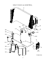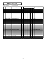
1
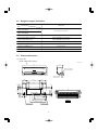
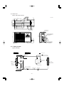
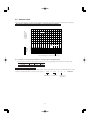
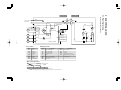
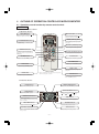
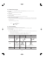
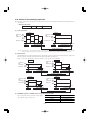
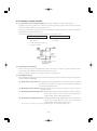
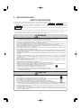
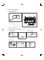
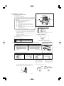
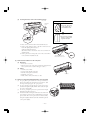
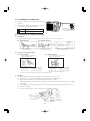
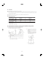
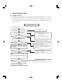
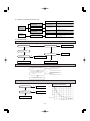
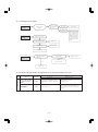
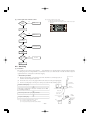
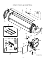
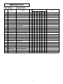
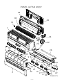
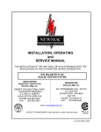
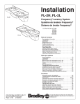
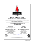
ROOM AIR-CONDITIONING
TECHNICAL MANUAL & PARTS LIST
WALL MOUNTED TYPE
ROOM AIR-CONDITIONER
(Split system, air cooled cooling only type)
SRK10CFV-4, 13CFV-4
TECHNICAL MANUAL
CONTENTS
1. GENERAL INFORMATION ............................................................................... 2
1.1 Specific features ........................................................................................ 2
1.2 How to read the model name .................................................................... 2
2. SELECTION DATA ............................................................................................ 3
2.1 Specifications ............................................................................................. 3
2.2 Range of usage & limitations .................................................................... 5
2.3 Exterior dimensions .................................................................................. 5
2.4 Piping system ............................................................................................. 6
2.5 Selection chart ........................................................................................... 7
3. ELECTRICAL DATA ......................................................................................... 8
3.1 Electrical wiring ......................................................................................... 8
4. OUTLINE OF OPERATION CONTROL BY MICROCOMPUTER .................... 9
4.1 Operation control function by remote control switch ............................ 9
4.2 Unit ON/OFF button ................................................................................. 10
4.3 Power blackout auto restart function .................................................... 11
4.4 Custom cord switching procedure ......................................................... 11
4.5 Flap and louver control ........................................................................... 12
4.6 3D auto operation .................................................................................... 12
4.7 Timer operation ........................................................................................ 13
4.8 Installation location setting .................................................................... 14
4.9 Outline of cooling operation ................................................................... 15
4.10 Outline of dehumidifying operation ....................................................... 16
4.11 Outline of automatic operation ............................................................... 17
4.12 Outline of fan operation .......................................................................... 17
4.13 Outline of clean operation ....................................................................... 17
4.14 Protective control function ..................................................................... 18
5. APPLICATION DATA ...................................................................................... 19
5.1 Selection of location for installation ...................................................... 20
5.2 Installation of indoor unit ........................................................................ 21
5.3 Installation of outdoor unit ..................................................................... 24
5.4 Connection of refrigerant pipings .......................................................... 24
5.5 Installation of remote control switch ..................................................... 25
5.6 Earthing work ........................................................................................... 25
5.7 Test run ...................................................................................................... 26
5.8 Precautions for wireless remote control installation and
operation ................................................................................................... 26
6. MAINTENANCE DATA .................................................................................... 27
6.1 Trouble shooting ...................................................................................... 27
6.2 Servicing ................................................................................................... 30
-
1-
1
GENERAL INFORMATION
1.1 Specific features
The “MITSUBISHI HEAVY INDUSTRIES, LTD.” room air-conditioner: SRK series are of split and wall mounted type and the unit
consists of indoor unit and outdoor unit with refrigerant precharged in factory. The indoor unit is composed of room air cooling equipment with operation control switch and the outdoor unit is composed of condensing unit with compressor.
(1) Remote control flap & louver
The flap & louver can be automatically controlled by operating wireless remote control.
¡ Flap swing
: The flaps swing up and down successively.
¡ Louver swing
: The louvers swing left and right successively.
¡ 3D auto operation
: Fan speed and air flow direction are automatically controlled, allowing the entire room to be
efficiently conditioned.
¡ Memory flap
: Once the flap & louver position is set, the unit memorizes the position and continues to operate
at the same position from the next time.
(2) Automatic operation
When the remote control switch is set on “auto (
) ”, it will either automatically decide operation mode such as cooling and
thermal dry, or operate in the operation mode before it has been turned to automatic control.
(3) Self diagnosis function
¡ We are constantly trying to do better service to our customers by installing such judges that show abnormality of operation as
follows.
RUN light
TIMER light
ON
TIMER light
1 time flash
Heat exchanger sensor error
2 time flash
Room temperature sensor error
6 time flash
RUN light
ON
2 time flash
Trouble of outdoor unit
Indoor fan motor error
1.2 How to read the model name
Example :
SR K 10 C FV -4
For Asia
Series No.
Cooling only type
Product capacity
Wall mounted type
Split type room air-conditioner
-
2-
2
SELECTION DATA
2.1 Specifications
Model
SRK10CFV-4 (Indoor unit)
SRC10CFV-4 (Outdoor unit)
(220V)
Model
SRK10CFV-4
Item
Cooling capacity(1)
SRC10CFV-4
BTU
9000
Power source
1 Phase, 220V, 50Hz
Operation
data(1)
Cooling input
kW
0.73
Running current (Cooling)
A
3.4
Inrush current
A
18
COP (In cooling)
3.62
Noise level(4)
Exterior dimensions
Height × Width × Depth
dB
39
45
mm
268 × 790 × 199
540 × 780 × 290
Fine snow
Stucco white
8.5
30
–
RSA201A018
Color
Net weight
Refrigerant equipment
Compressor types & Q’ty
kg
Motor
kW
Starting method
Heat exchanger
–
0.69
–
Line starting
Louver fins & inner grooved tubing
Refrigerant control
Louver fins & inner grooved tubing
Capillary tubes
Refrigerant(3)
kg
R22 0.9 (Pre-Charged up to the piping length of 7.5m)
Refrigerant oil
Air handling equipment
Fan type & Q’ty
R
0.35 (SUNISO 4GSI or ATMOS NM56)
Tangential fan × 1
Motor
Air flow (at High)
Propeller fan × 1
W
16
14
CMM
9.0
26.5
Air filter, Q’ty
Polypropylene net (washable) × 2
–
–
Cushion rubber (for compressor)
Shock & vibration absorber
Electric heater
Operation control
Operation switch
Room temperature control
Pilot lamp
–
–
Wireless-Remote control
–
Microcomputer thermostat
–
RUN (Green), TIMER (Yellow),
–
HI POWER (Green), 3D AUTO (Green)
Frost protection,
Safety equipment
Internal thermostat (for compressor)
Refrigerant
piping
Fan motor error protection
O.D
mm (in)
Liquid line: ø6.35 (1/4") Gas line: ø9.52 (3/8")
Connecting method
Attached length of piping
Flare connecting
Liquid line: 0.4 m
Gas line : 0.33 m
Insulation
–
Necessary (Both sides)
Drain hose
Connectable
Power source cord
Connection
wiring
2.5 m (3 cores with Earth)
Size × Core number
1.5 mm2 × 3 cores (Including earth cable)
Connecting method
Terminal block (Screw fixing type)
Accessories (included)
Mounting kit
Optional parts
–
Notes (1) The data are measured at the following conditions.
Item
Operation
Cooling
Indoor air temperature
DB
WB
27°C
19°C
Outdoor air temperature
DB
WB
35°C
24°C
(2) The operation data are applied to the 220 V districts respectively.
(3) The refrigerant quantity to be charged includes the refrigerant in 7.5 m connecting piping.
(Purging is not required even in the short piping.)
If the piping length is longer, when it is 7.5 to 15 m, add 10 g refrigerant per meter.
(4) Expressed in sound pressure level.
-
3-
Standards
ISO-T1, JIS C9612
Model
SRK13CFV-4 (Indoor unit)
SRC13CFV-4 (Outdoor unit)
(220V)
Model
SRK13CFV-4
Item
(1)
Cooling capacity
SRC13CFV-4
BTU
12500
Power source
1 Phase, 220V, 50Hz
Operation
data(1)
Cooling input
kW
1.06
Running current (Cooling)
A
4.9
Inrush current
A
29
COP (In cooling)
3.45
Noise level(4)
Exterior dimensions
Height × Width × Depth
dB
40
49
mm
268 × 790 × 199
540 × 780 × 290
Fine snow
Stucco white
8.5
37
–
RSA201A017
Color
Net weight
Refrigerant equipment
Compressor types & Q’ty
kg
Motor
kW
Starting method
Heat exchanger
–
1.09
–
Line starting
Louver fins & inner grooved tubing
Refrigerant control
Straight fins & inner grooved tubing
Capillary tubes
Refrigerant(3)
kg
R22 0.93 (Pre-Charged up to the piping length of 7.5m)
Refrigerant oil
Air handling equipment
Fan type & Q’ty
R
0.41 (SUNISO 4GSI or ATMOS NM56)
Tangential fan × 1
Motor
Air flow (at High)
Propeller fan × 1
W
16
22
CMM
9.5
29.5
Polypropylene net (washable) × 2
–
Shock & vibration absorber
–
Cushion rubber (for compressor)
Electric heater
Operation control
Operation switch
–
–
Wireless-Remote control
–
Microcomputer thermostat
–
Air filter, Q’ty
Room temperature control
Pilot lamp
RUN (Green), TIMER (Yellow),
–
HI POWER (Green), 3D AUTO (Green)
Frost protection,
Safety equipment
Internal thermostat (for compressor)
Refrigerant
piping
Fan motor error protection
O.D
mm (in)
Liquid line: ø6.35 (1/4") Gas line: ø12.7 (1/2")
Connecting method
Attached length of piping
Flare connecting
Liquid line: 0.4 m
Gas line : 0.33 m
Insulation
–
Necessary (Both sides)
Drain hose
Connectable
Power source cord
Connection
wiring
2.5 m (3 cores with Earth)
Size × Core number
1.5 mm2 × 3 cores (Including earth cable)
Connecting method
Terminal block (Screw fixing type)
Accessories (included)
Mounting kit
Optional parts
–
Notes (1) The data are measured at the following conditions.
Item
Operation
Cooling
Indoor air temperature
DB
WB
27°C
19°C
Outdoor air temperature
DB
WB
35°C
24°C
(2) The operation data are applied to the 220 V districts respectively.
(3) The refrigerant quantity to be charged includes the refrigerant in 7.5 m connecting piping.
(Purging is not required even in the short piping.)
If the piping length is longer, when it is 7.5 to 15 m, add 10 g refrigerant per meter.
(4) Expressed in sound pressure level.
-
4-
Standards
ISO-T1, JIS C9612
2.2 Range of usage & limitations
Models
All models
Item
Indoor return air temperature
(Upper, lower limits)
Refer to the selection chart
Outdoor air temperature
(Upper, lower limits)
Refrigerant line (one way) length
Max. 15m
Vertical height difference between
outdoor unit and indoor unit
Max. 5m (Outdoor unit is higher)
Max. 5m (Outdoor unit is lower)
Rating ± 10%
Power source voltage
Voltage at starting
Min. 85% of rating
Frequency of ON-OFF cycle
Max. 10 times/h
ON and OFF interval
Max. 3 minutes
2.3 Exterior dimensions
(1) Indoor unit
Models SRK10CFV-4, 13CFV-4
Unit: mm
A
→
790
199
3
9
60
268
Piping hole right(left)
Terminal block
138
450
206.5
202
450
133.5
102.5
585
7.5
43.2
39.3
102.5
45
53.5
Pipng for Gas
53.5
10 :ø9.52
380.6
13 :ø12.7
(
)
Pipng for Liquid 448.6 (ø6.35)
VIEW A
Drain hose 520 (ø16)
Piping hole (ø65)
Piping hole (ø65)
-
5-
27
45
60
45
252.2
60
8.3
44.5
44.5
200
788
17.5
(2) Outdoor unit
Models SRC10CFV-4, 13CFV-S
Unit: mm
111.4
99.4
290
312.5
350
43.1
313.1
23.5
Drain holes
50
12
14
349.5
439.1
104.9
510
780
165.1
18.9
61.9
2-16×12
Terminal block
33.5
540
138.4
Service valve (Liquid)
Flare connecting
ø6.35 (1/4")
42.5
95.9
14
40°
40°
Service valve (Gas)
Flare connecting
10: ø9.52 (3/8")
13: ø12.7 (1/2")
2.4 Piping system
Models All models
Indoor unit
Outdoor unit
Flare connecting
(
Piping
(Gas)
10 : ø9.52
13 : ø12.7
Cooling cycle
Service valve
(Gas)
Check joint
)
Accumulator
Room temp.
sensor
Heat
exchanger
Heat
exchanger
sensor
Heat
exchanger
Compressor
Piping
(Liquid)
ø6.35
Service valve (Liquid)
Capillary tube
Flare connecting
-
6-
Capillary tube
2.5 Selection chart
Correct the cooling capacity in accordance with the conditions as follows. The net cooling capacity can be obtained in the following way.
Net capacity = Capacity shown on specification ✕ Correction factors as follows.
(1) Coefficient of cooling capacity in relation to temperatures
1.3
Coefficient of cooling
capacity in relation
to temperature
1.2
Cooling
1.1
1.0
0.9
0.8
0.7
0.6
Outdoor air D.B.
temperature
°C D.B.
Cooling operation
Applicable range
43
40
35
30
25
20
15
24
14
16
18
20
22
Indoor air W.B. temperature °C W.B. ISO-T1 Standard Condition
(2) Correction of cooling capacity in relation to one way length of refrigerant piping
It is necessary to correct the cooling capacity in relation to the one way piping length between the indoor and outdoor units.
Piping length [m]
7
10
15
Cooling
1.0
0.99
0.975
How to obtain the cooling capacity
Example : The net cooling capacity of the model SRK13CFV-4 with the piping length of 15m, indoor wet-bulb temperature at 19.0˚C
and outdoor dry-bulb temperature 35˚C is Net cooling capacity =
12500
SRK13CFV-4
-
7-
✕
0.975
Length 15m
✕
1.0
=
Factor by air
temperatures
12187 BTU
BL
2
LM2
CNY
Wireless
R-Amp
ZNR
CNE
-
8-
Meaning of marks
Black
Symbol
BL
Blue
CC
Parts name
Capacitor for CM
Symbol
LM 1, 2
Parts name
Louver motor
BR
Brown
CFI
Capacitor for FM I
Th1, 2
Sensor
LB
Light blue
CFO
Capacitor for FM O
ZNR
Varistor
Y
Yellow
CM
Compressor motor
51C
Motor protector for CM
Fuse
52C
Magnetic contactor for CM
RD
F
Red
OR
Orange
FMI
Fan motor (Indoor unit)
WH
White
FMO
Fan motor (Outdoor unit)
Y/G
Yellow/Green
SM
Flap motor
T
Table of relay operations
Operation
Cooling
Relay symbol
52C
Control part
CM
Notes (1)
: denotes magnetized relay × : denotes demagnetized relay
(2) Th1 is room temperature sensor. Th2 (the heat exchanger sensor) is frost prevention sensor.
Terminal block
BK
L3
CM
CFo
Cc
Sh
Printed circuit board
BK
OR
L1
Display
Back up Sw
Color symbol
BK
FMo
RD
CNX
~
OR
LM1
Th2
WH
CNM
Th1
CNG
51C
1
WH
SM
3
2
L2
F
(250V 3.15A)
CNW
BK
52C
~
5
3
CONTROL BOX
52C4
WH
CFI
1
52C3
WH
1
WH
FMI
N
BR
1
WH
Y
WH
RD
CNU
WH
BK
WH
BR
BK
2
BK
LB
ELECTRICAL DATA
Power source
220V 50Hz
T
Y/GN
Models SRK10CFV-4, 13CFV-4
T
Y/GN
3
Outdoor unit
3.1 Electrical wiring
Indoor unit
4
OUTLINE OF OPERATION CONTROL BY MICROCOMPUTER
4.1 Operation control function by remote control switch
Remote control
Models SRK10CFV-4, 13CFV-4
◆ Operation selection
FAN SPEED button
OPERATION MODE select button
Each time the button is pushed, the
indicator is switched over in turn.
Each time the button pushed, the
indicator is switched over in turn.
ON/OFF (luminous) button
HI POWER/ECONO button
Press for starting operation, press again
for stopping.
This button changes the HIGH POWER/
ECONOMY mode.
AIR FLOW (UP/DOWN) button
This button changes the air flow (up/down) mode.
TEMPERATURE button
This button sets the room temperature.
(This button changes the present time and
TIMER time.)
AIR FLOW (LEFT/RIGHT) button
This button changes the air flow (left/right) mode.
3D AUTO button
ON TIMER button
This button sets 3D AUTO operation.
This button selects ON TIMER operation.
OFF TIMER button
SLEEP button
This button selects OFF TIMER operation.
This button changes to SLEEP operation.
RESET switch
Switch for resetting microcomputer and
setting time.
• The above illustration shows all controls, but in practice
only the relevant parts are shown.
CLEAN switch
This switch changes the CLEAN mode.
CANCEL button
This button cancels the ON timer, OFF
timer, and SLEEP operation.
◆ Indication selection
ON/OFF TIMER indicator
CLEAN indicator
Indicates during CLEAN operation.
Indicates during ON/OFF TIMER operation.
OPERATION MODE indicator
SLEEP indicator
Indicates selected operation with
lamp.
[ (Auto) • (Cool) •
(Fan) • (Dry)]
Indicates during SLEEP operation.
TEMPERATURE indicator
TIME indicator
Indicates set temperature.
(Does not indicate temperature when operation
mode is on AUTO)
Indicates present time or timer setting time.
AIR FLOW indicator
FAN SPEED indicator
Indicates set air flow rate with
lamp.
Shows selected flap and louver mode.
HI POWER/ECONO MODE indicator
3D AUTO indicator
Indicates during HIGH POWER/ECONOMY
mode operation.
Indicates during 3D AUTO operation.
-
9-
Unit indication selection
Models SRK10CFV-4, 13CFV-4
RUN light (green)
Illuminates during operation
and CLEAN operation.
TIMER light (yellow)
Illuminates during TIMER operation.
RUN
TIMER
HI POWER
ON / OFF
3D AUTO
HI POWER light (green)
Illuminates during HIGH POWER operation.
3D AUTO light (green)
Illuminates during 3D AUTO operation.
Models SRK10CFV, 13CFV
RUN light (green)
4.2 Unit ON/OFF button
Illuminates during operation
and CLEAN operation.
When the remote control batteries become weak, or if the remote control is lost or malfunctioning, this button may be used to turn the
TIMER light (yellow)
unit on and off.
Illuminates during TIMER operation.
(1) Operation
Push the button once to place the RUN
unit in the
automatic mode. Push it once
more toECONO
turn the unit off.
TIMER
HI POWER
ON / OFF
(2) Details of operation
POWER
TheHIunit
will golight
into(green)
the automatic mode in which it automatically determines, from room temperature (as detected by sensor),
Illuminates during HIGH POWER operation.
whether to go into the cooling or thermal dry modes.
ECONO light (orange)
Function
Room temperature
setting
Illuminates during ECONOMY operation.
Operation mode
Cooling
Thermal dry
Fan speed
Flap
Timer switch
Auto
Auto
Continuous
About 24ºC
About 24ºC
Unit ON/OFF button
-
10 -
4.3 Power blackout auto restart function
(1) Power blackout auto restart function is a function that records the operational status of the air-conditioner immediately prior to it
being switched off by a power cut, and then automatically resumes operations at that point after the power has been restored.
(2) The following settings will be cancelled:
Jumper wire (J7)
(a) Timer settings
(b) High-power operations
Notes (1) The power blackout auto restart function is set at on when the air-conditioner is shipped from the
factory. Consult with your dealer if this function needs to be switched off.
(2) When power failure ocurrs, the timer setting is cancelled. Once power is resumed, reset the timer.
(3) If the jumper wire (J7) “AUTO RESTART” is cut, auto restart is disabled. (See the diagram at right)
4.4 Custom cord switching procedure
If two wireless remote controls are installed in one room, in order to prevent wrong operation
due to mixed signals, please modify the printed circuit board in the indoor unit’s control box
and the remote control using the following procedure. Be sure to modify both boards. If only
one board is modified, receiving (and operation) cannot be done.
(1) Modifying the indoor unit’s printed circuit board
Take out the printed circuit board from the control box and cut off jumper wire (J6)
using wire cutters.
After cutting of the jumper wire, take measures to prevent contact with the other the lead
wires, etc.
(2) Modifying the wireless remote control
(a) Remove the battery.
(b) Cut the jumper wire shown in the figure at right.
Cut
-
11 -
Jumper wire (J6)
4.5 Flap and louver control
Control the flap and louver by AIRFLOW (LEFT/RIGHT) button on the wireless remote control.
(UP/DOWN) and
(1) Swing flap
Flap moves in upward and downward directions continuously.
(2) Swing louver
Louver moves in left and right directions continuously.
(3) When not operating
The flap returns to the position of air flow directly below, when operation has stopped.
(4) Memory flap (Flap or Louver stopped)
When you press the AIRFLOW (UP/DOWN or LEFT/RIGHT) button once while the flap or louver is operating, it stops swinging
at an angle. Since this angle is memorized in the microcomputer, the flap or louver will automatically be set at this angle when the
next operation is started.
¡ Recommendable stopping angle of the flap
COOL•DRY
Horizontal
blowing
4.6 3D auto operation
Control the flap and louver by 3D AUTO button on the wireless remote control.
Fan speed and air flow direction are automatically controlled, allowing the entire room to efficiently conditioned.
(1) Detail of operation
(a)
Perform STEP1 → STEP2 → STEP3 → STEP4 one time.
(b)
After performing STEP4 in (a) above, the next steps to be carried out are determined by the difference between the room
temperature and the setting temperature.
1) Room temperature – Setting temperature > 5ºC: STEP2 → STEP3 → STEP4 are performed.
2) Room temperature – Setting temperature <
= 5ºC: STEP3 → STEP4 are performed.
Operation step
Fan speed
STEP1
Setting fan speed
STEP2
Auto : HIGH POWER
Other than Auto: Setting fan speed
STEP3
STEP4
Setting fan speed
Flap
Louver
Left louver Right louver
Left louver Right louver
Left louver
Right louver
The left louver and right louver
The left louver and right louver
The
left
louver
and
right
louver
operate
in opposite directions to
operate in opposite directions to
operate in the same direction
each other on the left and right sides.
each other on the left and right sides. left and right.
Conditions for
jumping to next STEP
_
20 cycle
-
12 -
60 cycle
60 cycle
4.7 Timer operation
(1) Comfortable timer setting (ON timer)
If the timer is set at ON when the operation select switch is set at the cooling, or the cooling in auto mode operation is selected, the
comfortable timer starts and determines the starting time of next operation based on the initial value of 15 minutes and the relationship
between the room temperature at the setting time (temperature of room temperature sensor) and the setting temperature. (Max. 60
minutes)
Operation mode
Operation start time correction value (Min.)
3 < Room temp. – Setting temp.
1 < Room temp. – Setting temp. <
=3
Room temp. – Setting temp. <
=1
+5
No change
–5
At cooling
Notes (1) At 5 minutes before the timer ON time, operation starts regardless of the temperature of the room temperature sensor (Th1).
(2) This function does not actuate when the operation select switch is set at the dehumidifying as well as the dehumidifying in the auto mode.
However, the operation of item (1) above is performed during the dehumidifying in the auto mode.
(3) During the comfortable timer operation, both the run light and timer light illuminate and the timer light goes off after expiration of the timer, ON setting time.
(Example) Cooling
Room temperature
Corrects the starting time of next operation by
calculating the temperature difference.
¡ If the difference (= Room temperature – Setting temperature) is 4°C, the correction value is found to be +5 minutes from the table shown above so that the starting time
of next operation is determined as follows:
15 min. earlier + 5 min. = 20 min. earlier
↑
↑
Correction value
Current operation
start time
Setting temperature
Operation starting time
Time
15 min.
earlier
10 min.
earlier
5 min.
earlier
Setting time
(2) Sleep timer operation
Pressing the SLEEP button causes the temperature to be controlled as shown in the following chart with respect to the set temperature.
Cooling, DRY
+1.0
Temperature
setting (˚C)
0
-1.0
Timer operation
(time)
0
1.0
2.0
Start
(3) OFF timer operation
The Off timer can be set at a specific time (in 10-minute units) within a 24-hour period.
-
13 -
4.8 Installation location setting
When the indoor unit is installed at the end of a room, control the air flow direction so that it is not toward the side walls. If you set the
remote control’s installation position, keep it so that the air flow is within the range shown in the following figure.
(1) Setting
1
If the air conditioning unit is running, press the ON/OFF button to stop.
The installation location setting cannot be made while the unit is running.
2
Press the AIR FLOW
(UP/DOWN) button and the
AIRFLOW
(LEFT/RIGHT) button together for 5 seconds
or more.
The installation location display illuminates.
3
Setting the air-conditioning installation location.
Press the AIR FLOW
(LEFT/RIGHT) button and adjust to the desired
1, 4
location.
2
Each time the AIR FLOW
(LEFT/RIGHT) button is pressed, the
3
indicator is switched in the order of:
(Center Installation)
4
(Right End Installation)
(Left End Installation)
Press the ON/OFF button.
The air-conditioner's installation location is set.
Press within 60 seconds of setting the installation location (while the
installation location setting display illuminates).
Airflow range
(Left End Installation)
Airflow range
(Center Installation)
-
14 -
Airflow range
(Right End Installation)
4.9 Outline of cooling operation
(1) Operation of major fanctinal components
Item
When the compressor
command is OFF
When the compressor
command is ON
When the compressor goes
OFF due to an anomalous stop.
ON
ON
OFF
Flap and louver
ON or OFF
ON or OFF
Stop position control
Display
Lights up
Lights up
Lights up or flashes
52C
OFF
ON
OFF
Outdoor fan motor
OFF
ON
OFF
Functional
components
Indoor fan motor
(2) Fan speed switching
Fan speed switching
AUTO
Flow control
Swing flap or louver
Swing stop
Auto fan control
HIGH
MED
LOW
Speed 5
Speed 3
Speed 2
Speed 5
Speed 3
Speed 2
(a) Auto fan control
The indoor fan is automatically controlled in accordance with the difference between the room temperature (detected by the
room temperature sensor) and the termostat setting as shown below.
Speed 5
Speed 4
Speed 3
Speed 2
+1
Thermostat setting point
+2
+3
+4
(3) Thermostat operation
The compressor and outdoor fan and turned on and off as shown below according to the temperature setting.
ON
Compressor
Outdoor fan
OFF
-1
Room temp. Set temp.
(4) HIGH POWER operation ( “HI POWER” button on the remote control : ON)
The following operation is performed for 15 minutes without relation to the set temperature or fan speed setting.
Indoor unit fan
Speed 6 fixed
Outdoor unit fan
ON
Compressor
ON
Notes (1) Room temperature is not adjusted during the HIGH POWER operation.
(2) Protective functions will actuate with priority even during the HIGH POWER
operation.
(5) ECONOMY operation ( “ECONO” button on the remote control : ON)
The set temperature changes as shown at right, and the
indoor unit fan speed is set on speed 2.
-
Running time
Set temperature compensation
Running start ~ 1 hour
Set temperature +0.5
1~2 hours
Set temperature +1.0
2 hours ~
Set temperature +1.5
15 -
4.10 Outline of dehumidifying operation
(1) Choose the appropriate operation block area by the difference between room temperature and thermostat setting temperature as
shown below.
¡ Operation block area
D Block
C Block
–2
Room temp.
B Block
A Block
0
+3
– Setting temp.(deg)
(2) Start up operation
C.D Block
A.B Block
Compressor ON
and
outdoor fan
Compressor ON
and
outdoor fan OFF
OFF
Speed 2
Speed 1
Indoor fan
Speed 2
OFF
20
Indoor fan
seconds
0
3
Start
6
9
OFF
12 minutes
12 minutes
0
Temperature check
Temperature check
Start
Operation block decision
Note (1) Thermostat operation is performed in A, B Block. When compressor and indoor fan stop by thermostat operation within 12 minutes from start, temperature
check is performed by operating indoor fan at speed 1 for 20 seconds before finishing 12 minutes and allowing decision of next operation block.
(3) DRY operation
After finishing start up operation described in (2) above, thermal dry operation is performed at 8 minutes intervals, according to the
difference between room temperature and thermostat setting temperature as shown below.
Beside, 1 cycle of this operating time consists of 8 minutes, 7 cycle operation is performed then.
D Block
C Block
Compressor ON
and
outdoor fan OFF
Speed 2
Speed 1
Indoor fan
OFF
Compressor
and
OFF
outdoor fan
Speed 1
Indoor fan
OFF
20 seconds
8 minutes
0
Start
0
Temperature check
20 seconds
3
Start
8 minutes
Temperature check
Operation block decision
B Block
A Block
Compressor ON
and
outdoor fan OFF
Compressor ON
and
outdoor fan OFF
Speed 2
Indoor fan Speed 1
Speed 2
Indoor fan
OFF
OFF
20 seconds
0
Start
4
0
8 minutes
Temperature check
8 minutes
Start
Temperature check
Operation block decision
(4) ECONOMY operation ( “ECONO” button on the remote control : ON)
The set temperature changes as shown at right, and the
indoor unit fan speed is set on speed 2.
-
Running time
Set temperature compensation
Running start ~ 1 hour
Set temperature +0.5
1~2 hours
Set temperature +1.0
2 hours ~
Set temperature +1.5
16 -
4.11 Outline of automatic operation
(1) Determination of operation mode
The blow operation of the indoor fan is carried out at the 1st speed for 20 seconds and the room temperature is checked to
determine the operation mode automatically. (When the unit is operated by the turn-on timer, the blow operation is not carried out.)
Room temperature<26°C
26°C<=Room temperature
Dry
Cooling
Operation mode
(2) Within 30 minutes after either auto or manual operation stops, if auto operation is started, or if you switch to auto operation during
manual operation, the system runs in the previous operation mode.
(3) The temperature is checked 1 time in 30 minutes after the start of operation, and if the judgment differs from the previous operation
mode, the operation mode changes.
(4) Setting temperature can be adjusted within the following range. There is the relationship as shown below between the signals of the
wireless remote control and the setting temperature.
Signals of wireless remote control (Display)
–2
–1
±0
+1
+2
+3
+4
+5
+6
Setting
Cooling
16
17
18
19
20
21
22
23
24
25
26
27
28
temperature
Dehumidifying
17
18
19
20
21
22
23
24
25
26
27
28
29
–6
–5
–4
–3
4.12 Outline of fan operation
(1) Operation of major fanctional components
Fan speed switching
Functional
components
52C
HIGH
POWER
Indoor fan motor
Speed 6
AUTO
HIGH
MED
LOW
ECONOMY
Speed 3
Speed 2
Speed 1
OFF
Speed 5
Speed 4
Outdoor fan motor
OFF
Flap and louver
ON or OFF
(2) HIGH POWER operation (“HI POWER” button on the remote control : ON)
The following operation is performed for 15 minutes without relation to the set fan speed.
Indoor unit fan
Speed 6 fixed
Outdoor unit fan
OFF
Compressor
OFF
Note (1) Protective functions will actuate with priority even during the HIGH POWER operation.
4.13 Outline of clean operation
COOL,DRY,AUTO (COOL,DRY); after operation has stopped, the moisture inside the dryer air conditioner, controls the production of
fungus etc.
(1) Operating condition
‘Clean’ is switched ON, when the air conditioner receives a STOP signal.
(2) Detail of operation
Compressor
OFF
Indoor fan motor
Speed 1
Outdoor fan motor
OFF
Flap and louver
Fully closed
(3) Reset condition
When control finishes 120 minutes after the Clean operation starts. When the stop signal is received from the remote control.
-
17 -
4.14 Protective control function
(1) Frost prevention for indoor heat exchanger [Preventing frost accumulation on the indoor heat exchanger]
During the Cooling or Dry operation in low room air temp. condition, evaporating temperature will decrease and consequently
indoor heat exchanger sometimes gets clogged with frost (or ice).
In order to prevent this trouble, compressor is stopped by under mentioned condition by indoor heat exchanger sensor (Th2) and
timer (built into microcomputer circuit) functions.
Also indoor fan is changed over to protects the fan tap just before frost prevention control.
CM, FMO stoppage condition
1
CM, FMO re-starting condition
Temperature of heat exchanger is
1
Temperature of heat exchanger is
2.5˚C or lower.
2
8˚C or higher.
As least 3 minutes has passed since
the compressor started.
Protects
the fan
tap just
before
frost
prevention
control
Set fan
speed
2.5
8
Indoor heat exchanger
temperature (˚C)
(2) Three-minute forced operation
When the compressor begins operating the thermal operation is not effective for 3 minutes, so operation continues as is in the
operation mode. (After 3 minutes has passed the thermal operation is effective.)
However, stopping the compressor via a stop signal or protection control has priority.
(3) Self diagnosis function
When something abnormal happens on the outdoor unit, indoor unit fan motor and each sensor (heat exchanger, room temperature),
it will be indicated by flashing lights.
(a) Abnormality of outdoor unit: When the indoor heat exchanger temperature does not fall to 25°C or below for 40 minutes
after 5 minutes have elapsed since the compressor operation start, the abnormality stop
occurs. (The timer light flashes 2 times.)
(b) Abnormality of indoor fan motor: The indoor fan motor revolves at a rate under 300 rpm for 30 seconds or longer, the
RUN light will flash.
(c) Abnormality of heat exchanger sensor: RUN light will flashing when the input temperature of the heat exchanger
sensor measures less than –20°C for more than 15 seconds with the air
conditioner “OFF”. (will not flashing during operation)
(d) Abnormality room temperature sensor: RUN light will flashing when the input temperature of the room temperature
sensor measures less than –20°C for more than 15 seconds with the air
conditioner “OFF”. (will not flashing during operation)
Note (1) If the above abnormalities happen concurrently, the light will flashing in the order of item number (a) through (d) above.
-
18 -
5
APPLICATION DATA
SAFETY PRECAUTIONS
¡ Please read these “Safety Precautions” first then accurately execute the installation work.
¡ Though the precautionary points indicated herein are divided under two headings,
WARNING and
CAUTION , those points
which are related to the strong possibility of an installation done in error resulting in death or serious injury are listed in the
WARNING section. However, there is also a possibility of serious consequences in relationship to the points listed in the
CAUTION section as well. In either case, important safety related information is indicated, so by all means, properly observe all
that is mentioned.
¡ After completing the installation, along with confirming that no abnormalities were seen from the operation tests, please explain
operating methods as well as maintenance methods to the user (customer) of this equipment, based on the owner’s manual.
Moreover, ask the customer to keep this sheet together with the owner’s manual.
WARNING
¡ To disconnect the appliance from the mains supply this appliance must be connected to the mains by means of
a circuit breaker or a switch (use a recognized 20A) with a contact separation of at least 3mm.
¡ The appliance shall be installed in accordance with national wiring regulations.
¡ This system should be applied to places as households, residences and the like. Application to inferior environment such as engineering shop could cause equipment malfunction.
¡ Please entrust installation to either the company which sold you the equipment or to a professional contractor.
Defects from improper installations can be the cause of water leakage, electric shocks and fires.
¡ Execute the installation accurately, based on following the installation manual. Again, improper installations can
result in water leakage, electric shocks and fires.
¡ For installation, confirm that the installation site can sufficiently support heavy weight. When strength is insufficient, injury can result from a falling of the unit.
¡ For electrical work, please see that a licensed electrician executes the work while following the safety standards
related to electrical equipment, and local regulations as well as the installation instructions, and that only exclusive use circuits are used.
Insufficient power source circuit capacity and defective installment execution can be the cause of electric shocks
and fires.
¡ Accurately connect wiring using the proper cable, and insure that the external force of the cable is not conducted
to the terminal connection part, through properly securing it improper connection or securing can result in heat
generation or fire.
¡ Take care that wiring does not rise upward, and accurately install the lid/service panel.It’s improper installation
can also result heat generation or fire.
¡ When setting up or moving the location of the air conditioner, do not mix air etc. or anything other than the
designated refrigerant (R22) within the refrigeration cycle.
Rupture and injury caused by abnormal high pressure can result from such mixing.
¡ Always use accessory parts and authorized parts for installation construction. Using parts not authorized by this
company can result in water leakage, electric shock, fire and refrigerant leakage.
¡ Ventilate the work area when refrigerant leaks during the operation.
Coming in contact with fire, refrigerant could generate toxic gas.
¡ Confirm after the foundation construction work that refrigerant does not leak.
If coming in contact with fire of a fan heater, a stove or movable cooking stove, etc., refrigerant leaking in the
room could generate toxic gas.
CAUTION
¡ Execute proper grounding. Do not connect the ground wire to a gas pipe, water pipe, lightning rod or a telephone
ground wire.
Improper placement of ground wires can result in electric shock.
¡ The installation of an earth leakage breaker is necessary depending on the established location of the unit.
No installing an earth leakage breaker may result in electric shock.
¡ Do not install the unit where there is a concern about leakage of combustible gas.
The rare even of leaked gas collecting around the unit could result in an outbreak of fire.
¡ For the drain pipe, follow the installation manual to insure that it allows proper drainage and thermally insulate it
to prevent condensation. Inadequate plumbing can result in water leakage and water damage to interior items.
¡ Install the outdoor unit so that the aluminum fins on the air heat exchanger cannot be touched. Failure to
observe this may result in injury.
¡ Do not place objects near the outdoor unit or allow leaves to gather around the unit. If there are objects or leaves
around the outdoor unit, small animals may enter unit and contact electrical parts resulting in break down,
emission of smoke or flame.
-
19 -
5.1 Selection of location for installation
(1)
Indoor unit
(a)
Where there is no obstructions to the air flow and where the cooled
air can be evenly distributed.
(b)
A solid place where the unit or the wall will not vibrate.
(c)
A place where there will be enough space for servicing. (Where
6.5 cm
space mentioned right can be secured)
(d)
Where wiring and the piping work will be easy to conduct.
(e)
The place where receiving part is not exposed to the direct rays of
Right
side
Left
side
10 cm
5 cm
the sun or the strong rays of the street lighting.
(f)
A place where it can be easily drained.
(g)
A place separated at least 1m away from the television or the radio.
(To prevent interfence to images and sounds.)
(2)
Outdoor unit
(a)
A place where good air circulation can be obtained and where rain, snow or sunshine will not directly strike the unit.
(b)
A place where discharged hot air or unit’s operating sound will not be a nuisance to the neighborhood.
(c)
A place where servicing space can be secured.
(d)
A place where vibration will not be enlarged.
* Avoid installing in the following places.
• A place near the bedroom and the like, so that the operation noise will cause no trouble.
• A place where there is possibility of flammable gas leakage.
• A place exposed to strong wind.
(e)
Do not install the unit near the seaside, or where there is possibility of chlorine gas generation.
Air intake
10 cm
MIN
Air outlet
)
(
No obstacles
(Service
space for
electrical
parts)
Air
intake
(3)
Notes (1) Blowing out port and suction port on the back side of the unit can be
installed at a distance of 10cm from walls.
In case the barrier is 1.2m or above in height, or is overhead, the
sufficient space between the unit and wall shall be secured.
(2) When the unit is installed, the space of the following dimension and
above shall be secured.
10 cm MIN
60 cm MIN
Limitations for one way piping length and vertical
height difference.
Model
Item
One way piping length (R)
Outdoor
Vertical height unit is lower
difference (h) Outdoor unit
is higher
All models
h
15 m
r
5m
5m
-
20 -
5.2 Installation of indoor unit
(1) Installation of installation board
Fixing of installation board
Look for the inside wall structures (Intersediate support or
pillar and firaly install the unit after level surface has been
checked.)
450
INSTALLATION SPACE (INDOOR UNIT)
(FRONT VIEW)
Unit : mm
65
39.3
43.2
Space
138
206.5
102.5
200
44.5
252.2
Mating mark for level surface
44.5
Adjustment of the installation board in the horizontal
direction is to be conducted with four screws in a
temporary tightened state.
7.5 for service
Space for
Indoor unit
service
100
Installation board
450
202
133.5
450
102.5
585
Space for
service
50
53.5
53.5
Piping for Gas 380.6
Piping for Liquid 448.6
Drain hose 520( 16)
Space * 15
for service
8.3
(a)
Standard hole
Piping hole( 65)
Piping hole( 65)
* Leave extra space on the right side to enable removal of the lid screw.
Adjust so that board will be level by turning the board
with the standard hole as the center.
(2) Drilling of holes and fixture sleeve (Option Parts)
When drilling the wall that contains a metal lath, wire lath or metal plate, be sure to use pipe hole sleeve sold separately.
(a)
Drill a hole with ø65
(b) Adjusting sleeve length
whole core drill
Cut off the sleeve
collar in case of
drawing piping out
to rear.
Indoor side
Cut off the sleeve
collar that can be
seen from beneath
the unit.
Outdoor side
Wall thickness
+ 1.5 cm
Note (1) Drill a hole with incline of 5 degree from
indoor side to outdoor side.
(c)
Install the sleeve
(Inserting sleeve)
(*Sleeve + *Inclined + *Sealing plate)
Turn to
tighten
View of sleeve when installed
Inclined
flange
Sealing
Sleeve
plate
Paste
Indoor side
Outdoor side
-
21 -
Indoor side
Outdoor side
(3) Preparation of indoor unit
Terminal block
(a) Mounting of connecting wires
1) Remove the lid.
2) Remove the wiring clamp.
3) Connect the connecting wire securely to the terminal block.
Use cable for interconnection wiring to avoid loosening
of the wires.
CENELEC code for cables Required field cables.
H05RNR3G1.5 (Example) or 245IEC57
H
Harmonized cable type
05 300/500 volts
R
Natural-and/or synth. rubber wire insulation
N
Polychloroprene rubber conductors insulation
R
Standed core
4or5 Number of conductors
G
One conductor of the cables is the earth conductor
(yellow/green)
1.5 Section of copper wire (mm2)
Lid
*Leave space to allow removal of this screw after installation.
(b) Shaping the pipe
Pipe
• Connect the connection wire securely to the terminal
block. If the wire is not affixed completely, contact will
be poor, and it is dangerous as the terminal block may
heat up and catch fire.
• Take care not to confuse the terminal numbers for indoor
and outdoor connections.
• Affix the connection wire using the wiring clamp.
4) Fix the connecting wire by wiring clamp.
5) Attach the lid.
6) Close the air inlet panel.
1
Brown
For power supply, indoor outdoor
2
Blue
For power supply, indoor outdoor
Clamp
Screw *
Drain hose
•
Hold the bottom of the pipe and change its direction
before stretching it and shaping it.
(c) Taping of the exterior
•
Tape only the portion that runs through the wall.
Always tape the crossover wires with the pipe.
(d) Cautions when piping from the left and the rear center of the unit
[ Top View ]
Left Side Piping
Piping is possible in the rear, left,
left rear, left downward, right or
downward direction.
Right Side Piping
Left rear piping
Right rear piping
Right
Left side piping
Right side piping
Rear
Downward Left rear
Left
Left downward
[ Procedure for exchanging the drain hose ]
1. Remove the drain hose.
2. Remove the drain cap.
• Loosen and remove the
spring-type clamp.
• Remove with your hand or
a pair of pliers.
• Do not place the power supply cords above the gutter, because the
air conditioner is structured in a way where condensation on the
back side is collected in to the drain pan before drainage.
3. Insert the drain cap.
4. Connect the drain hose.
• Use a hexagonal wrench to
correctly insert the drain cap
which was removed in 2.
Caution: Be careful because
if the cap is not inserted
property, water leak may
occur.
• Loosen the spring-type clamp
and securely insert the drain
hose.
Caution: Be careful because if
the cap is not inserted properly,
water leak may occur.
• Do not make traps in the drain hose line.
Gutter
Declining slope
Wall
Pipes storage area
-
22 -
Inverted slipe
Trap
(e) Securing the indoor unit to the installation board
Indoor unit
Installing steps
Installation
board
Latch (2 locations)
1.Hook the upper part
of the indoor unit to
the installation board.
Installation
board
2.The unit can be installed
simply by gently pushing in the lower part.
Wall
Indoor unit
base lower latch
• How to remove the indoor unit from the installation board
1) Push up at the marked portion of the indoor unit base lower
latch, and slightly pull it toward you.
(both right and left hand sides)
(The indoor unit base lower latch can be removed from the installation board)
2) Push up the indoor unit upward. So the indoor unit will be
removed from the installation board.
Lid
The marked portion of the
Indoor unit bese lower latch
(4) Removal and installation of the front panel
(a) Removing
• Remove the 2 set screws.
• Move the lower part of the panel forward and push upwards to
remove. (Remove the 3 latches in the upper section.)
(b) Fitting
• Do remove the air filter.
• Cover the body with the front panel.
• Push the circled portion at the front.
• Tighten the 2 set screws.
• Fit the air filter. Carry out in the above order.
Set screws
(5) Open/close and detachment/attachment of air inlet panel
(a)
(b)
(c)
(d)
To open, pull the panel at both ends of lower part and release
latches, then pull up the panel until you feel resistance. (The
air inlet panel stops at approx. 60˚ open position.)
To close, hold the panel at both ends of lower part to lower
downward and push it slightly until the latch works, then push
the center portion slightly.
To remove, pull up the panel to the position shown in right
illustration and pull it toward you.
To install, insert the air inlet panel arm into the slot on the front
panel from the position shown in right illustration, hold the
panel at both ends of lower part, lower it downward slowly,
then push it slightly until the latch works and further push the
center portion slightly.
-
23 -
5.3 Installation of outdoor unit
(1)
Make sure that the unit is stable in installation. Fix the unit to
stable base.
(2)
Terminal block
1 2
Perfrom wiring, making wire terminal numbers conform to terminal numbers of indoor unit terminal block.
1
Brown
For power supply, indoor outdoor
2
Blue
For power supply, indoor outdoor
Interconnecting wire
5.4 Connection of refrigerant pipings
(1) Preparation
Keep the openings of the pipes covered with tapes etc. to prevent dust, sand, etc. from entering them.
(a)
(b) Outdoor unit side
Indoor unit side
Dimension A
Liquid side
(ø6.35): 9.0 dia
Gas side
(ø9.52): 13.0 dia
(ø12.7): 16.2 dia
Press
(Do not
turn)
Remove
¡ Remove the flared nuts.
(on both liquid and gas sides)
Remove
¡ Remove the flared nuts.
(on both liquid and gas sides)
¡ Install the removed flared nuts to the pipes to be
connected, then flare the pipes.
(2) Connection of refrigerant piping
(a)
(b) Outdoor unit side
Indoor unit side
• Connect firmly gas and liquid side
pipings by Torque wrench.
• Connect firmly gas and liquid side
pipings by Torque wrench.
Spanner
for fixing
the piping)
Torque
wrench
• Specified torquing value:
Liquid side (ø6.35) : 14~18N·m (1.4~1.8kgf·m)
Gas side (ø9.52)
: 34~42N·m (3.4~4.2kgf·m)
Gas side (ø12.7)
: 49~61N·m (4.9~6.1kgf·m)
• Specified torquing value:
Liquid side (ø6.35) : 14~18N·m (1.4~1.8kgf·m)
Gas side (ø9.52)
: 34~42N·m (3.4~4.2kgf·m)
Gas side (ø12.7)
: 49~61N·m (4.9~6.1kgf·m)
• Use one more spanner to fix the valve.
• Always use a Torque wrench and back up spanner to tighten the flare nut.
(3) Air purge
(a)
Tighten all flare nuts in the pipings both indoor and outside wall so as not to cause leak.
(b)
Connect service valve, charge hose, manifold valve and vacuum pump as is illustrated below.
(c)
Open manifold valve handle Lo to its full width, and perform vacuum or evacuation.
Continue the vacuum or evacuation operation for 15 minutes or more and check to see that the vacuum gauge reads – 0.1 MPa
(– 76 cmHg).
(d)
After completing vacuum operation, fully open service valve (Both gas and liquid sides) with hexagon headed wrench.
(e)
Detach the charge hoses.
(f)
Check for possible leakage of gas in the connection parts of both indoor and outdoor.
Compound Pressure
(Gauge)
gauge
-76 cm Hg
Handle Lo
(pressure)
Stop valve
(Two-way valve)
Stop value
(Three-way
value)
Manifold
Valve
Handle Hi
(pressure)
Charge hose
Service port
Vacuum pump
Charge hose
-
24 -
♦ Additional refrigerant charge
When refrigerant piping exceeds 7.5m conduct additional refrigerant charge after refrigerant sweeping.
7.5m over 15m:Additional charge amount per meter = 10g/m
[Example]
How much amount of additional charge for 15m piping?
(15 – 7.5)m × 10g/m=75g
75g for additional charge
(4) Insulation of connecting portion
(a)
Cover the connection portion of the refrigerant piping with the
Vinyl tape
pipe cover and seal them.
To cover the connecting portion with insulation materials, cut upper portion and then seal
it with insulation materials.
If neglecting to do so, moisture occurs on the piping and water
will drip out.
(b) Finishing and fixing
Insulation
Refrigerant piping
Electrical wiring
Covering tape
Drain hose
1) Tie up the piping with wrapping tape, and shape it so that it
conforms to which the pipe is attached.
2) Fix them with clamps as right figure.
Cover the exterior portion with covering tape and shape the piping so it
will match the contours of the route
that the piping to take. Also fix the
wiring and pipings to the wall with
clamps.
Tapping screw
5.5 Installation of remote control switch
(1) Mounting method of battery
(b) Fixing to pillar or wall
• Uncover the remote control switch, and mount the batteries [R03(AAA, Micro)×2 pieces] in the body regularly.
(Fit the poles with the indication marks, , & . without fail)
• Conventionally, operate the wireless remote control by
holding in your hand.
• Avoid installing it on a clay wall etc.
Battery
+
+
Cover
Screws
5.6 Earthing work
• Earth work shall be carried out without fail in order to prevent electric shock and noise generation.
• The connection of the earth cable to the following substances causes dangerous failures, therefore it shall never be done.
City water pipe, Town gas pipe, TV antenna, lightning conductor, telephone line, etc.
-
25 -
5.7 Test run
(1) Conduct trial run after confirming that there is no gas leaks.
(2) When conducting trial run set the remote control thermostat to continuous operation position. However when the power source is
cut off or when the unit’s operation switch is turned off or was turned to fan operation position, the unit will not go into operation
in order to protect the compressor.
(3) Explain to the customer on the correct usage of the air conditioner in simple layman’s terms.
(4) Make sure that drain flows properly.
(5) Standard operation data
(220V)
Model
Item
Low pressure (MPa)
Temp. difference between
return air and supply air (°C)
SRK10CFV-4
SRK13CFV-4
0.46~0.66
0.41~0.61
10~12
13~15
3.4
4.9
Running current (A)
Note (1) The data are measured at following conditions
Ambient air temperature
Indoor side: Cooling ... 27˚C DB, 19˚C WB
Outdoor side: Cooling ... 35˚C DB, 24˚C WB
5.8 Precautions for wireless remote control installation and operation
(1)
Wireless remote control covers the following distances:
(a)
When operating facing the air conditioner:
7
m
or
le
ss
Wireless remote
control
7 m or less
or les
s or le
ss
or less
Notes (1) The remote control is correctly facing the
sensing element of the air conditioner when being
manipulated.
(2) The typical coverage is indicated (in the left
illustration). It may be more or less depending on
the installation.
(3) The coverage may be less or even nil. If the sensing
element is exposed to strong light, such as direct
sunlight, illumination, etc., or dust is deposited on
it or it is used behind a curtain, etc.
If the distances exceed the area indicated above, be sure to check
the receiver status.
(b) When manipulating the remote control mounted on a
Receiver
wall:
Make sure that it works normally (i.e., transmission/reception
signal is audible) before mounting.
Remote control
available in this area.
-
26 -
6
MAINTENANCE DATA
6.1 Trouble shooting
(1) Trouble shooting to be performed prior to exchanging PCB, (Printed circuit board) [Common to all models]
All the models described in this chapter are controlled by a microcomputer. When providing maintenance service to customers it
is necessary to understand the function controlled by a microcomputer thoroughly, so as not to mistakenly identify correct operations as mis-operations. It is also necessary to perform the following simple checks before conducting detailed checks or exchanging printed circuit board.
Before exchanging Printed circuit board
Claim call from the user
Ascertain the nature of the claim.
Unit did not cool, etc.
¡ Is the power on?
¡ Is the thermostat setting correct?
(Not too high?)
¡ Is the unit in a timer operation?
¡ Does user understand function?
etc.
Ascertain the operation status.
Is this nonsense claim?
YES
No
Operate the unit.
¡ Explain the function of the unit to user.
Does the trouble occur again?
No
No need for PCB change
Check further the status when the trouble occured
(such as the timer of occurence, power failures, thunder, use status of other electrical appliances, etc).
Clarify the reason for the problem and explain it thoroughly to the user.
YES
Temporarily turn off the power source and
turn it on again in about 1 min. and turn the
unit on again.
Does the trouble occur again?
No
No need for PCB change
Microcomputer runaway due to power source
conditions is a possible cause.
YES
Disconnect connectors and connect them
again.
Operate the unit again after confirming that the fuse
and the varistor equipped on PCB does not burn out.
No
Does the trouble occur again?
YES
Carry out checks according to detailed
check process (See later page)
-
27 -
No need for PCB change
The cause is defective connector contact.
(2) Indication of Self Diagnosis (Indoor unit)
Connect of Defect
TIMER light is
lights
continuously.
RUN light is
lights
continuously.
Place of defect
RUN light is flashing.
(1 Time flash.)
Abnormality of heat
exchanger sensor.
¡ Disconnection of heat exchanger sensor.
RUN light is flashing.
(2 Time flash.)
Abnormality of room
temperature sensor.
¡ Disconnection of room temperature
sensor.
RUN light is flashing.
(6 Time flash.)
Abnormality of indoor
fan motor.
¡ Fan motor is defective.
¡ Printed circuit board is defective.
TIMER light is flashing.
(2 Time flash.)
Abnormality of outdoor
unit.
¡ Compressor is defective.
¡ Capacitor is defective.
¡ Gas is short.
(3) Troubleshooting
Abnormality of outdoor unit
[Compressor malfunction of insufficient gas (refrigerant)]
No
Is protective device normal?
Does compressor operate?
No
Replace protective device.
Yes
Yes
Is refrigerant circulation
volume normal?
Yes
Is abnormality the same after
gas charging?
Is capacitor normal?
No
No
Replace capacitor.
Insufficient gas.
Yes
Yes
Replace compressor.
Clogging of capillary tube. etc.
Abnormality of indoor fan motor
(Fan motor defective, printed circuit board defective)
No
Is the connector connection
good?
Repair the connector.
Yes
No
Is voltage being applied to the
fan motor?
The indoor circuit board
is defective.
Yes
The fan motor is defective.
Abnormality of sensor
Disconnection of sensor and defective connection of connector
Chart for sensor temperature
resistance characteristics
No
Repair connector.
(Disconnection)
Resistance value
Is connection to connector
good?
Yes
Is sensor resistance value
normal?
No
Replace sensor.
Yes
(kΩ)
Replace PCB.
(Short circuit)
Temperature (°C)
-
28 -
(4) Trouble Diagnostic Procedures
Unit malfunctions or
does not stop.
Indoor light of
indoor unit does not
illuminate.
Remove receptacle.
Insert it after 3 min.
and operate.
Runaway of microcomputer
No change.
Replace PCB.
Normal operation.
Microcomputer rarely
mis-starts even during
times or power supply
or power failure, but, it
can sometimes occur
during those times. If it
occurs, check the operation, when the result is
positive then proceed as
normal.
Check receptacle voltage.
Check if PCB fuse is blown.
Replace fuse.
Check varistor
Replace varistor.
Replace PCB.
Abnormal
Outdoor fan does not
operate.
Yes
Check voltage with fan
connector.
Check capacitor.
Replace capacitor.
Normal
Replace fan motor.
No
Replace PCB.
(5) Trouble shooting chart for the room temperature sensor (Th1), heat exchanger sensor (Th2)
Indoor unit
Unit
sensor
Room temperature
sensor (1) (Th1) except for
“continuous” thermal
setting.
Heat exchanger
sensor (Th2)
Operation
Cooling
Cooling
Function
Short circuit
Continuous Cooling operation
¡ Cannot be turned ON/OFF by thermostat
¡ When FMI is on. “AUTO” is continuously
Hi
Cooling will not operate.
Broken connection
Cooling will not operate
¡ FMI : continuous operation
¡ CM,FMo: stopped
Cooling will operate
¡ Heat exchanger frost preventer begins to operate
¡ Cools alternately for 10 minutes, stopping for 3
minutes.
Note (1) When the room temperature sensor (Th1) will not operate normally. Cooling operation may be run continuously by putting the thermostat setting on “CONTINUOUS”
-
29 -
(6) How to make sure of remote control
(1)
Is remote
control
normal?
NO
Remote control
defects
YES
Abnormal is not
fount
NO
Control unit defects
Note (1) How to check the remote control.
(a) Press the reset switch of remote control.
(b) If the almost normal if entire display of remote control is shown after 1
indication.
YES
Again pushing
operating switch
Operating the
unit?
NO
Does operating Unit
ON/OFF button
Operating the unit?
YES
Replace the
display
Operating the
unit by remote
control?
YES
It is normal
NO
Remote control
defects
6.2 Servicing
(1) Evacuation
The evacuation is an procedure to purge impurities ...... noncondensable gas, air, moisture from the refrigerant equipment by using
a vacuum pump. Since the refrigerant R22 is very insoluble in water, even a small amount of moisture left in the refrigerant
equipment will freeze, causing what is called water clogging.
¡ Evacuation procedure
(a)
Check to ensure that there is no internal pressure in the unit. If there is an internal pressure, it
should be relieved through the check joint.
(b)
Connect the service hoses of the gauge manifold to the check joint of the gas & liquid piping.
(c)
Connect a vacuum pump to the charge hose A. Repeat evacuation in the following sequence.
Liquid side
Start the vacuum pump
Gas side
Operate the vacuum pump for more than 15 minutes after –0.1MPa
(–76 cmHg) is indicated.
Check joint
Close low pressure valve 1 of gauge manifold.
Service hose
Gauge
manifold
Stop the vacuum pump.
Charge hose
Notes (1) Do not use the refrigerant pressure to expel air.
(2) Do not use the compressor for evacuation.
(3) Do not operate the compressor in the vacuum condition.
Vacuum
pump
-
30 -
Refrigerant
cylinder
(2) Refrigerant charge
(a)
Discharge refrigerant entirely from the unit and evacuate the unit.
Note: Addition of refrigerant without evacuation is unreasonable, because it will result in low charge or overcharge.
(b)
Keep the gauge manifold and connect a refrigerant cylinder to the unit.
(c)
Record the weight of the refrigerant cylinder on the balance. This is necessary for making sure of the charged refrigerant
amount.
(d)
Purge air from the charge hose A .
Firstly loose the connecting portion of the charge hose A at the gauge manihold side and open the valve 3 for a few
seconds, and then immediately retighten it after observing that gas is blow out from the loosened portion.
(e)
Open the valve 1 and 3 after discharging air from the charge hose A , then the gas refrigerant begins flowing from the
cylinder into the unit. Be sure to erect the refrigerant cylinder upright to let gas refrigerant flow into the unit.
(f)
When refrigerant has been charged into the system to some extent, refrigerant flow becomes stagnant, when that happens,
start the compressor in cooling cycle until the unit is filled with gas to the specified weight.
(g)
Making sure of the refrigerant amount, close the valve 3.
(h)
Disconnect the charge hose from the unit. Cover the valve ports of the refrigerant piping with caps and tighten them securely.
(i)
Check for gas leakage applying a gas leak detector along the piping line.
(j)
Start the air conditioner and make sure of its operating condition ...... high side and low side pressures and temperature
difference between return air and supply air.
-
31 -
PARTS LIST
INDOOR UNIT
SRK10CFV-4, SRK13CFV-4
OUTDOOR UNIT
SRC10CFV-4, SRC13CFV-4
PANEL & FAN ASSY
28
30
33
31
1
34
5
7
4
35
6
3
29
27
5
14
35
4 9
12
26
14
12
16
21
22
2
32
8
10
14 10
- 33 -
11
21
18
19
20
24 15
13
25
23
17
22
22
CRAE0175
SRK10CFV-4
END ITEM NO. :
No.
RWA002F050D
Part No.
Part Name
1-6 RKX 102A 001B PANEL ASSY,FRONT
RE.Q
Recommendable Purchased Q'ty
10
1
30
50
Note
100 500 1000
1
1
1
2
1 RKX 122A 001B PANEL,FRONT
1
2 RKX 435A 004
PANEL ASSY,AIR IN
1
1
1
2
3
3 RKX 437A 001
FILTER,AIR
2
1
1
1
2 W315×H294.3(t2)
4 RKX 129A 013
CAP
2
5 RKX 129A 014
HOLDER,FILTER
2
1
1
1
2
6 RKX 133A 001
PLATE,ORNAMENT
1
1
1
1
2
1
1
2
3
7-27 RKX 435A 002
GRILLE ASSY,AIR OUT
1
7 RKX 435A 003
GRILLE,AIR OUTLET
1
8 RKX 436A 001
FLAP(A)
1
UPPER
9 RKX 436A 002
FLAP(B)
1
LOWER
LOUVER ASSY(R)
1
10 RKX 436A 005
LOUVER
6
11 RKX 129A 008
PLATE,CONNECTING(R)
1
LOUVER ASSY(L)
1
12 RKX 436A 005
LOUVER
6
13 RKX 129A 009
PLATE,CONNECTING(L)
1
14 RKW 935C 200
COLLAR
6
15 RKX 129A 010
BRACKET,MOTOR(A)
16 RKX 129A 011
10・11 RKX 436A 003
1
1
2
2
1
1
2
2
1
1
1
1
2
BRACKET,MOTOR(B)
1
1
1
1
2
17 RKX 129A 012
BRACKET,MOTOR(C)
1
1
1
1
2
18 RKX 144A 001
LINK
1
1
1
1
2
19 RKX 144A 002
CRANK(A)
1
1
1
1
2
20 RKX 144A 003
CRANK(B)
1
1
1
1
2
21 RKW 144A 204
CRANK(C)
2
1
1
1
2
22 SSA 512T 052
MOTOR,STEPPING
3
1
1
1
2 FOR FLAP/LOUVER(R,L)
23 RKS 504A 100G HARNESS ASSY
1
1
1
1
2 FOR FLAP
24 RKS 504A 100
HARNESS ASSY
1
1
1
1
2 FOR LOUVER(R)
25 RKS 504A 100L
HARNESS ASSY
1
1
1
1
2 FOR LOUVER(L)
26 SSA 423A 094
HOSE,DRAIN
1
12・13 RKX 436A 004
27 SSA 326A 047
PLUG
1
28 RKX 111A 001
BASE ASSY
1
1
1
1
2
29 SSA 511J 218
MOTOR,AC
1
1
1
1
2 FOR IMPELLER
30 SSA 431G 044
IMPELLER
1
1
1
2
4
31 SSA 923C 114
BEARING,PLANE
1
1
1
1
2
32 RKX 129A 005
COVER(MOTOR)
1
1
1
1
2
33 RKX 032A 001
PLATE,INSTALLATION
1
1
1
1
2
34 RKX 132A 001A LID
1
1
1
2
4
35 SSA 913A 007A SCREW,TAP
4
- 34 -
4×14
HEAT EXCH. & CONTROL
7
8
6
5
3
17
18
1
4
13
19
2
9
21
23
16
22
10
24
25
11
15
12
14
20
CRAE0176
- 35 -
SRK10CFV-4
END ITEM NO. :
No.
Part No.
RWA002F050D
Part Name
1-4 RKX 301A 002A HEAT EXCH ASSY(AIR)
RE.Q
Recommendable Purchased Q'ty
10
1
30
50
Note
100 500 1000
1
1
1
2
2 RKX 315D 001
HEADER ASSY
1
3 RKX 129A 016
BRACKET(L)
1
4 RKX 315A 001
DISTRIBUTOR ASSY
1
PIPE ASSY
1
6 SSA 323F 082
UNION(SLD)
1
FOR GAS
7 SSA 323F 082A
UNION(SLD)
1
FOR LIQ.
8 RKX 129A 001
PLATE ASSY,BAFFLE
1
9 RKX 142A 001
BOX,CONTROL
1
5-7 RKX 321A 001
1
1
1
2
10-12 RKX 505A 001B PWB ASSY
1
2
2
4
8
11 SSA 555B 050C VARISTOR
1
1
1
1
2
12 SSA 564A 132
FUSE(CURRENT)
1
1
1
2
4 F 3.15A
13 SSA 551A 163L
SENSOR ASSY
1
1
1
2
4 INCL.SENSOR(ROOM TEMP.& HEAT EXCH.)
14 RKV 504A 500
HARNESS ASSY(POWER)
1
1
1
1
2
15 SSA 561B 713
BLOCK,TERMINAL
1
1
1
2
2
16 RKX 011G 001
LABEL,WIRING
1
17 RKX 503A 001
DISPLAY ASSY
1
1
1
2
3
18 RKX 505A 003
PWB ASSY(DISPLAY)
1
2
2
4
8
19 RKJ 941F 001
SPRING,LEAF
1
20 RKX 008A 003B PARTS,STANDARD
1
21 RKX 502A 001
CONTROL ASSY,REMOTE
1
2
3
5
10
22 RKT 437A 011
FILTER,CLEAN
1
2
2
4
8
23 RKT 437A 005
FILTER,LIGHT CLEAN
1
2
2
4
8
24 RMA 012A 017
MANUAL,INSTRUCTION
1
1
1
2
1
25 RKN 032A 002B HOLDER(REMO-CON)
1
(26) RMA 011F 003AT LABEL,MODEL NAME
1
- 36 -
PANEL & FAN ASSY
28
30
33
31
1
34
5
7
4
35
6
3
29
27
5
14
35
4 9
12
26
14
12
16
21
22
2
32
8
10
14 10
- 37 -
11
21
18
19
20
24 15
13
25
23
17
22
22
CRAE0175
SRK13CFV-4
END ITEM NO. :
No.
RWA002F050F
Part No.
Part Name
1-6 RKX 102A 001B PANEL ASSY,FRONT
RE.Q
Recommendable Purchased Q'ty
10
1
30
50
Note
100 500 1000
1
1
1
2
1 RKX 122A 001B PANEL,FRONT
1
2 RKX 435A 004
PANEL ASSY,AIR IN
1
1
1
2
3
3 RKX 437A 001
FILTER,AIR
2
1
1
1
2 W315×H294.3(t2)
4 RKX 129A 013
CAP
2
5 RKX 129A 014
HOLDER,FILTER
2
1
1
1
2
6 RKX 133A 001
PLATE,ORNAMENT
1
1
1
1
2
1
1
2
3
7-27 RKX 435A 002
GRILLE ASSY,AIR OUT
1
7 RKX 435A 003
GRILLE,AIR OUTLET
1
8 RKX 436A 001
FLAP(A)
1
UPPER
9 RKX 436A 002
FLAP(B)
1
LOWER
LOUVER ASSY(R)
1
10 RKX 436A 005
LOUVER
6
11 RKX 129A 008
PLATE,CONNECTING(R)
1
LOUVER ASSY(L)
1
12 RKX 436A 005
LOUVER
6
13 RKX 129A 009
PLATE,CONNECTING(L)
1
14 RKW 935C 200
COLLAR
6
15 RKX 129A 010
BRACKET,MOTOR(A)
16 RKX 129A 011
10・11 RKX 436A 003
1
1
2
2
1
1
2
2
1
1
1
1
2
BRACKET,MOTOR(B)
1
1
1
1
2
17 RKX 129A 012
BRACKET,MOTOR(C)
1
1
1
1
2
18 RKX 144A 001
LINK
1
1
1
1
2
19 RKX 144A 002
CRANK(A)
1
1
1
1
2
20 RKX 144A 003
CRANK(B)
1
1
1
1
2
21 RKW 144A 204
CRANK(C)
2
1
1
1
2
22 SSA 512T 052
MOTOR,STEPPING
3
1
1
1
2 FOR FLAP/LOUVER(R,L)
23 RKS 504A 100G HARNESS ASSY
1
1
1
1
2 FOR FLAP
24 RKS 504A 100
HARNESS ASSY
1
1
1
1
2 FOR LOUVER(R)
25 RKS 504A 100L
HARNESS ASSY
1
1
1
1
2 FOR LOUVER(L)
26 SSA 423A 094
HOSE,DRAIN
1
12・13 RKX 436A 004
27 SSA 326A 047
PLUG
1
28 RKX 111A 001
BASE ASSY
1
1
1
1
2
29 SSA 511J 218
MOTOR,AC
1
1
1
1
2 FOR IMPELLER
30 SSA 431G 044
IMPELLER
1
1
1
2
4
31 SSA 923C 114
BEARING,PLANE
1
1
1
1
2
32 RKX 129A 005
COVER(MOTOR)
1
1
1
1
2
33 RKX 032A 001
PLATE,INSTALLATION
1
1
1
1
2
34 RKX 132A 001A LID
1
1
1
2
4
35 SSA 913A 007A SCREW,TAP
4
- 38 -
4×14
HEAT EXCH. & CONTROL
12
11
10
9
3
7
21
22
5
1
6
17
23
4
8
2
13
25
27
20
26
14
28
29
15
19
16
18
24
CRAE0177
- 39 -
SRK13CFV-4
END ITEM NO. :
No.
Part No.
1-8 RKX 301A 008
RWA002F050F
Part Name
RE.Q
HEAT EXCH ASSY(AIR)
1
2 RKX 315D 005
HEADER ASSY
1
3 RKX 129A 016
BRACKET(L)
1
DISTRIBUTOR ASSY
1
4 RKX 315A 003
DISTRIBUTOR
1
5 RKX 315B 001
CAPILLARY
1
6 RKX 315B 002
CAPILLARY
1
7 RKX 315B 005
CAPILLARY
1
8 RKX 315B 006
CAPILLARY
1
9-11 RKX 321A 001A PIPE ASSY
1
4-8 RKX 315A 004
Recommendable Purchased Q'ty
10
30
50
Note
100 500 1000
1
1
1
2
10 SSA 323F 082B
UNION(SLD)
1
FOR GAS
11 SSA 323F 082A
UNION(SLD)
1
FOR LIQ.
12 RKX 129A 001
PLATE ASSY,BAFFLE
1
13 RKX 142A 001
BOX,CONTROL
1
1
1
1
2
14-16 RKX 505A 001C PWB ASSY
1
2
2
4
8
15 SSA 555B 050C VARISTOR
1
1
1
1
2Z
16 SSA 564A 132
FUSE(CURRENT)
1
1
1
2
4 F 3.15A
17 SSA 551A 163L
SENSOR ASSY
1
1
1
2
4 INCL.SENSOR(ROOM TEMP.& HEAT EXCH.)
18 RKV 504A 500
HARNESS ASSY(POWER)
1
1
1
1
2
19 SSA 561B 713
BLOCK,TERMINAL
1
1
1
2
2
20 RKX 011G 001
LABEL,WIRING
1
21 RKX 503A 001
DISPLAY ASSY
1
1
1
2
3
22 RKX 505A 003
PWB ASSY(DISPLAY)
1
2
2
4
8
23 RKJ 941F 001
SPRING,LEAF
1
24 RKX 008A 003B PARTS,STANDARD
1
25 RKX 502A 001
CONTROL ASSY,REMOTE
1
2
3
5
10
26 RKT 437A 011
FILTER,CLEAN
1
2
2
4
8
27 RKT 437A 005
FILTER,LIGHT CLEAN
1
2
2
4
8
28 RMA 012A 017
MANUAL,INSTRUCTION
1
1
1
1
2
29 RKN 032A 002B HOLDER(REMO-CON)
1
(30) RMA 011F 003AV LABEL,MODEL NAME
1
- 40 -
PANEL & FAN ASSY
8
15
6
9
18
12
5
11
10
13
17
17
17
4
2
14
16
3
1
7
7
CRBE0233
- 41 -
SRC10CFV-4
END ITEM NO. :
No.
RWC003F056D
Part No.
Part Name
RE.Q
Recommendable Purchased Q'ty
10
30
50
1 RCS 122A 500
PANEL ASSY,FRONT
1
1
1
1
2
2 RCS 123A 001
PANEL,SIDE(R)
1
1
1
1
2
3 RCS 132A 001
PANEL,SERVICE
1
1
1
2
4
4 RCS 435A 002A GRILL ASSY,AIR OUT
1
1
1
2
3
5 SSA 944B 036
1
HANDLE
Note
100 500 1000
6 SSA 913A 034B SCREW,TAP
17
4×8
7 SSA 913A 034C SCREW,TAP
3
4×12
8 RCS 124A 500
PANEL ASSY,TOP
1
9 RCS 116A 006
BRACKET ASSY
1
10 SSA 511J 221
MOTOR,AC
1
11 RCS 141A 500
PLATE,BAFFLE
1
12 SSA 431B 213
PROPELLER
1
13 RSA 914B 002
NUT,FLANGE
1
14 RCS 111A 001D BASE ASSY
1
15 RSA 011H 016A LABEL,NOTICE
1
16 RCS 116A 502
BRACKET
1
17 W011D04X008
TAP-SCREW,CRS-TRS 2
4
18 D100X20X036R INSULATION
1
- 42 -
1
1
1
2
2
2
4
8
1
1
2
4
1
1
1
2
4×8
HEAT EXCH. & CONTROL
1
2
17
23
19
3
16
15
14
21
13
22
5
20
18
7
9
4
(LIQ.)
10
6
12
11
8
(GAS)
CRBE0234
- 43 -
SRC10CFV-4
END ITEM NO. :
No.
RWC003F056D
Part No.
Part Name
1-3 RCS 301A 001B HEAT EXCH ASSY(AIR)
RE.Q
10
1
2 RCP 321A 035A PIPE
1
3 RCS 321A 003A PIPE
1
4・5 RCS 304A 002
Recommendable Purchased Q'ty
30
50
100 500 1000
1
1
1
2
1
1
1
2
Note
PIPING ASSY
1
4 RCS 315B 001
CAPILLARY
1
5 RCS 315B 002
CAPILLARY,SUB
1
6 RCS 116A 004
BRACKET,VALVE
1
7 RCS 381A 001
VALVE,SERVICE(1/4")
1
1
1
1
2 LIQ.
8 RCS 381A 002
VALVE,SERVICE(3/8")
1
1
1
1
2 GAS
9 RSA 201A 018
COMPRESSOR ASSY
1
1
2
3
8
10 RSA 914C 001
NUT,FLANGE
2
11 RMC 941C 002
CUSHION,RUBBER
3
12 RCS 154D 001
INSULATION,COMP
1
13 RSA 932C 005
GASKET,COVER
1
14 RSA 947K 006
COVER,TERMINAL
1
1
1
2
4
15 RSA 914C 002
NUT,FLANGE
1
16 SSA 552A 842
CAPACITOR,RUNNING
1
1
1
1
2 CFO 1.8MF 450VAC
17 SSA 552A 843A CAPACITOR,RUNNING
1
1
1
1
2 CC 25MF 370VAC
18 RSA 533B 004
PROTECTOR,MOTOR
1
1
1
1
2
19 SSA 561B 669
BLOCK,TERMINAL
1
1
1
2
2
20 RCS 504A 001
WIRING ASSY
1
1
1
1
2 FOR COMP.
21 RCS 142A 500
COVER(TB)
1
22 RCS 116A 500
BRACKET(TB)
1
23 SSA 937A 812
CLAMP
1
(24) RMC 011F 002ASLABEL,MODEL NAME
1
- 44 -
PANEL & FAN ASSY
8
15
6
9
12
5
11
10
13
17
17
17
4
2
14
16
3
1
7
7
CRBE0239
- 45 -
SRC13CFV-4
END ITEM NO. :
No.
RWC003F056F
Part No.
Part Name
RE.Q
Recommendable Purchased Q'ty
10
30
50
1 RCS 122A 500A PANEL ASSY,FRONT
1
1
1
1
2
2 RCS 123A 001
PANEL,SIDE(R)
1
1
1
1
2
3 RCS 132A 001
PANEL,SERVICE
1
1
1
2
4
4 RCS 435A 002A GRILL ASSY,AIR OUT
1
1
1
2
3
5 SSA 944B 036
1
HANDLE
Note
100 500 1000
6 SSA 913A 034B SCREW,TAP
17
4×8
7 SSA 913A 034C SCREW,TAP
3
4×12
8 RCS 124A 500
PANEL ASSY,TOP
1
9 RCS 116A 006
BRACKET ASSY
1
10 SSA 511J 222
MOTOR,AC
1
11 RCS 141A 500
PLATE,BAFFLE
1
12 SSA 431B 213
PROPELLER
1
13 RSA 914B 002
NUT,FLANGE
1
14 RCS 111A 001C BASE ASSY
1
15 RSA 011H 016A LABEL,NOTICE
1
16 RCS 116A 502
BRACKET
1
17 W011D04X008
TAP-SCREW,CRS-TRS 2
4
- 46 -
1
1
1
2
2
2
4
8
1
1
2
4
1
1
1
2
4×8
HEAT EXCH. & CONTROL
1
2
18
24
4
20
17
16
3
15
22
14
23
6
21
19
8
10
(LIQ.)
11
7
13
12
5
9
(GAS)
CRBE0235
- 47 -
SRC13CFV-4
END ITEM NO. :
No.
RWC003F056F
Part No.
1-4 RCS 301A 101
Part Name
RE.Q
HEAT EXCH ASSY(AIR)
1
2 RCS 321A 054
PIPE ASSY
1
3 RCS 321A 053
PIPE
1
4 RCS 321A 055
PIPE ASSY
1
PIPING ASSY
1
5 RCS 315B 012
CAPILLARY
1
6 RCS 315B 004
CAPILLARY,SUB
1
7 RCS 116A 004
BRACKET,VALVE
1
8 RCS 381A 001
VALVE,SERVICE(1/4")
9 RCS 381A 003
Recommendable Purchased Q'ty
10
30
50
100 500 1000
1
1
1
2
1
1
1
2
1
1
1
1
2 LIQ.
VALVE,SERVICE(1/2")
1
1
1
1
2 GAS
10 RSA 201A 017
COMPRESSOR ASSY
1
1
2
3
8
11 RSA 914C 001
NUT,FLANGE
2
1
1
2
4
5・6 RCS 304A 005
12 RMC 941C 002A CUSHION,RUBBER
3
13 RCS 154D 002
INSULATION,COMP
1
14 RSA 932C 005
GASKET,COVER
1
15 RSA 947K 006
COVER,TERMINAL
1
16 RSA 914C 002
NUT,FLANGE
1
Note
17 SSA 552A 842A CAPACITOR,RUNNING
1
1
1
1
2 CFO 2.5MF 450VAC
18 SSA 552A 843B CAPACITOR,RUNNING
1
1
1
1
2 CC 30MF 400VAC
19 RSA 533B 005
PROTECTOR,MOTOR
1
1
1
1
2
20 SSA 561B 669
BLOCK,TERMINAL
1
1
1
2
2
21 RCS 504A 001
WIRING ASSY
1
1
1
1
2 FOR COMP.
22 RCS 142A 500
COVER(TB)
1
23 RCS 116A 500
BRACKET(TB)
1
24 SSA 937A 812
CLAMP
1
(25) RMC 011F 002AT LABEL,MODEL NAME
1
- 48 -
ROOM AIR-CONDITIONING
TECHNICAL MANUAL & PARTS LIST
Manual No. '06·SRK-T·056