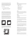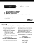
1
HIGH-DEFINITION VIDEO PROCESSOR & HUB
DVDO by Anchor Bay Technologies, Inc.
983 University Avenue, Building A
Los Gatos, CA 95032 USA
Tel: 866-423-DVDO (3836)
Fax: 408-379-3845
www.dvdo.com
Customer Support
Tel: 866-423-DVDO (3836) Extension 333
[email protected]
Owner’s Manual
DVDO BY ANCHOR BAY TECHNOLOGIES, INC.
LIMITED WARRANTY
WARRANTY VALID ONLY IN THE U.S.A.
WARRANTY
DVDO by Anchor Bay Technologies, Inc. (DVDO) warrants that products distributed in the U.S.A. that fail to function properly under normal use due to a
manufacturing defect when installed and operated according to the owner’s manual enclosed with the unit will be repaired or replaced with a unit of comparable
value, at the option of DVDO, without charge to you for parts or actual repair work. Parts supplied under this warranty may be new or rebuilt at the option
of DVDO.
THIS LIMITED WARRANTY APPLIES TO THE ORIGINAL OWNER OF THIS DVDO PRODUCT DURING THE WARRANTY PERIOD
PROVIDED THE PRODUCT WAS PURCHASED FROM AN AUTHORIZED DVDO DISTRIBUTOR/DEALER IN THE U.S.A. YOU WILL BE
REQUIRED TO PROVIDE A SALES RECEIPT OR OTHER VALID PROOF OF PURCHASE SHOWING THE DATE OF ORIGINAL PURCHASE.
IN THE EVENT SERVICE IS REQUIRED, THE PRODUCT MUST BE DELIVERED WITHIN THE WARRANTY PERIOD, TRANSPORTATION
PREPAID, ONLY FROM WITHIN THE U.S.A. AS EXPLAINED IN THIS DOCUMENT. YOU WILL BE RESPONSIBLE FOR REMOVAL AND
INSTALLATION OF THE PRODUCT. DVDO WILL PAY TO RETURN THE REPAIRED OR REPLACEMENT PRODUCT TO YOU WITHIN THE U.S.A.
PRODUCT WARRANTY PERIOD
PartsLabor
iScan Video Processors ....................................................................................................................1 Year
1 Year
Shorter periods may apply to some products. Please refer to the limited warranty document enclosed with your specific product for a definitive statement of the warranty period.
The warranty period for retail customers who rent the product commences upon the date product is first put into use (a) during the rental period or (b) retail sale, whichever occurs first.
WHAT IS NOT COVERED
IF THIS PRODUCT WAS PURCHASED FROM AN UNAUTHORIZED DEALER OR DISTRIBUTOR, THERE ARE NO WARRANTIES, EXPRESS OR
IMPLIED, INCLUDING THE IMPLIED WARRANTY OF MERCHANTABILITY AND THE IMPLIED WARRANTY OF FITNESS FOR A PARTICULAR
PURPOSE AND THIS PRODUCT IS SOLD STRICTLY “AS IS” AND “WITH ALL FAULTS”.
DVDO SHALL NOT BE LIABLE FOR ANY CONSEQUENTIAL AND/OR INCIDENTAL DAMAGES.
THIS WARRANTY DOES NOT APPLY IF THE PRODUCT HAS BEEN SUBJECTED TO POWER IN EXCESS OF ITS PUBLISHED POWER RATING.
THIS WARRANTY DOES NOT COVER THE CABINET OR ANY APPEARANCE ITEM, ANY DAMAGE TO RECORDING TAPES OR DISCS, TELEVISION
OR DISPLAY SCREENS DAMAGED BY STATIC, NON-MOVING, IMAGES APPLIED FOR LENGTHY PERIODS (BURN-IN), ANY DAMAGE TO THE
PRODUCT RESULTING FROM ALTERATIONS, MODIFICATIONS NOT AUTHORIZED IN WRITING BY DVDO, ACCIDENT, MISUSE OR ABUSE,
DAMAGE DUE TO LIGHTNING OR TO POWER SURGES, SUBSEQUENT DAMAGE FROM LEAKING, DAMAGE FROM INOPERATIVE BATTERIES, OR
THE USE OF BATTERIES NOT CONFORMING TO THOSE SPECIFIED IN THE OWNER’S MANUAL.
THIS WARRANTY DOES NOT COVER THE COST OF PARTS OR LABOR WHICH WOULD BE OTHERWISE PROVIDED WITHOUT CHARGE UNDER
THIS WARRANTY OBTAINED FROM ANY SOURCE OTHER THAN A DVDO AUTHORIZED SERVICE COMPANY OR OTHER DESIGNATED LOCATION.
THIS WARRANTY DOES NOT COVER DEFECTS OR DAMAGE CAUSED BY THE USE OF UNAUTHORIZED PARTS OR LABOR OR FROM IMPROPER
MAINTENANCE.
ALTERED, DEFACED, OR REMOVED SERIAL NUMBERS VOID THIS ENTIRE WARRANTY.
NO OTHER WARRANTIES
DVDO LIMITS ITS OBLIGATIONS UNDER ANY IMPLIED WARRANTIES INCLUDING, BUT NOT LIMITED TO, THE IMPLIED WARRANTIES OF
MERCHANTABILITY AND FITNESS FOR A PARTICULAR PURPOSE, TO A PERIOD NOT TO EXCEED THE WARRANTY PERIOD. NO WARRANTIES SHALL
APPLY AFTER THE WARRANTY PERIOD. SOME STATES DO NOT ALLOW LIMITATIONS ON HOW LONG AN IMPLIED WARRANTY LASTS AND SOME
STATES DO NOT ALLOW THE EXCLUSIONS OR LIMITATIONS OF INCIDENTAL OR CONSEQUENTIAL DAMAGES, SO THE ABOVE LIMITATIONS OR
EXCLUSIONS MAY NOT APPLY TO YOU. THIS WARRANTY GIVES YOU SPECIFIC LEGAL RIGHTS AND YOU MAY HAVE OTHER RIGHTS WHICH MAY
VARY FROM STATE TO STATE.
TO OBTAIN SERVICE
DVDO has appointed a number of Authorized Service Companies throughout the U.S.A. should your product require service. To receive warranty service you
need to present your sales receipt or, if rented, your rental contract showing place and date of original owner’s transaction. If shipping the unit you will need
to package it carefully and send it, transportation prepaid by a traceable, insured method, to the Authorized Service Company. Package the product using
adequate padding material to prevent damage in transit. The original container is ideal for this purpose. Include your name, address and telephone number
where you can be reached during business hours.
On all complaints and concerns in the USA call Customer Support at 1-866-423-3836.
For hook-up and operation of your unit or to locate an Authorized Service Company, please call or write:
TECHNICAL SUPPORT DEPARTMENT
DVDO BY ANCHOR BAY TECHNOLOGIES, INC.
983 University Avenue, Building A
Los Gatos, CA 95032
1-866-423-3836
http://www.DVDO.com
DISPUTE RESOLUTION
Following our response to any initial request to Customer Support, should a dispute arise between you and DVDO, DVDO makes available its Complaint
Resolution Program to resolve the dispute. The Complaint Resolution Program is available to you without charge. You are required to use the Complaint
Resolution Program before you exercise any rights under, or seek any remedies, created by Title I of the Magnuson-Moss Warranty-Federal Trade Commission
Improvement Act, 15 U.S.C. 2301 et seq.
To use the Complaint Resolution Program call 1-866-423-3836 and explain to the customer service representative the problem you are experiencing, steps
you have taken to have the product repaired during the warranty period and the name of the authorized Distributor/Dealer from whom the DVDO product
was purchased. After the complaint has been explained to the representative, a resolution number will be issued. Within 40 days of receiving your complaint,
DVDO will investigate the dispute and will either:
(1) respond to your complaint in writing informing you what action DVDO will take, and in what time period, to resolve the dispute; or (2) respond to your
complaint in writing informing you why it will not take any action.
RECORD THE PLACE AND DATE OF PURCHASE FOR FUTURE REFERENCE
Model No. ____________________________________________ Serial No. ___________________________________________ Purchase Date _______________________
Purchased From ______________________________________________________________________________________________________________
KEEP THIS INFORMATION AND YOUR SALES RECEIPT IN A SAFE PLACE
Ta b l e o f C o n t e n t s
S e ct i o n 1 – G e tt i n g St a r t e d 2
Introduction 2
Unpacking and Inspection 2
Display Compatibility Requirements 3
Document Conventions 3
Menu Navigation 3
Remote Control Battery Installation 4
Remote Control Overview 4
Info Screen 5
Installation Guidelines 6
S e ct i o n 2 – B a s i c O p e r a t i o n 7
Front Panel Overview 7
Rear Panel Overview 7
Video Inputs 8
Video Outputs 8
Audio Inputs 8
Audio Outputs 9
12V Trigger Outputs 9
RS232 Serial Connection 9
Power Supply Input 9
S e ct i o n 3 – S e t u p 10
Initial Set-Up 10
STEP 1 - Power Up 10
STEP 2 - Connect the iScan VP50PRO to the Display 10
STEP 3 - Selecting the Optimal Output Resolution on the iScan VP50PRO for the Connected Display(s) 10
STEP 4 - Connecting the Sources to the iScan VP50PRO 12
STEP 5 - Configuring the Sources to Get Maximum Performance 12
STEP 6 - Deinterlacing Mode and PReP™ 14
STEP 7 - Assigning Audio Inputs to Video Inputs 15
STEP 8 - Display Optimization – Using Display Adjustments 15
STEP 9 - Source Optimization – iScan Adjustments 16
i S C AN V P 5 0 PRO
T ABLE OF C ON T EN T S
Advanced Setups Configuration 26
Configuring the iScan VP50PRO for projectors with
17
Test Patterns 26
anamorphic lenses Configuring the iScan VP50PROto output 24/48/72Hz
Auto Standby 26
and 25/50/75Hz
LED Brightness 26
User Mode 27
Serial Port Rate 27
Factory Default 27
Software Update 27
12V Trigger Levels 27
Information 27
S e ct i o n 4 – M e n u O p t i o n s 18
Input Select 18
Input Aspect Ratio Control 18
Frame Aspect Ratio Active Aspect Ratio Output Setup 27
19
Analog/Digital 28
19
Output Format 28
Output Aspect Ratio Control 28
Panorama 19
Zoom 20
Sync Type 30
20
Color Space 30
Output Level 30
Pan Borders 20
Presets 21
Framerate Conversion 30
Border Level 32
Picture Controls
32
HDCP Mode 32
Input Adjust Control 22
Mosquito Noise Reduction 22
Deinterlacing 22
12V Triggers
32
PReP™, Progressive ReProcessing 23
Display Profiles 33
Pass Through 23
Overscan 23
Image Shift 23
Color Space 23
Input Level 24
VCR Mode 24
HDMI Configuration 24
Auto Input Priority Selection 24
Audio Input 25
AV Lip Sync™ 25
Picture Controls 25
Fine Detail 25
Edge Enhancement 25
Brightness 25
Contrast 25
Saturation 25
Hue 26
Y/C Delay 26
Chroma Filter (Auto CUE-C™) 26
S e ct i o n 5 – C O M PLE T E M ENU T REE 34
S e ct i o n 1 – G e tt i n g St a r t e d
Introduction
Thank you for purchasing the iScan VP50PRO video processor, the first VRS (Video Reference
Series) component available with:
• Mosquito Noise Reduction
•Fine Detail Enhancement™
•Edge Enhancement
VRS Technologies included in the iScan VP50PRO are:
•10-bit Precision Deinterlacing™ of 480i/576i/1080i
•10-bit Precision Video Scaling™ up to 1080p
•PReP™, Progressive ReProcessing of 480p/576/1080p
•Progressive Cadence Detection™ of 480p/576p/720p/1080p
•Rightrate™ High Performance Frame Rate Conversion
In addition to our own award winning video processing technologies, the iScan VP50PRO also
offers a host of other innovative features, including:
•
•
•
•
4 HDMI 1.3 (High Definition Multimedia Interface) Inputs and 1 HDMI 1.3 Output
THX Video Certification
ISF ccc Certification
2 Programmable 12 V Triggers to control other devices
This Owner’s Manual can help you set up your iScan VP50PRO, and give you the information
required to understand the total. It can also show you how to properly connect it and use it with
the other components in your system.
Unpacking and Inspection
Please verify that your iScan VP50PRO carton contains the following items:
• iScan VP50PRO Video Processor
•Universal 6V@7A AC-to-DC Power Converter
• US IEC Power Cord (International Customers, consult your local authorized DVDO reseller)
•Remote Control
• iScan VP50PRO Owner’s Manual
• iScan VP50PRO Quick Start Guide
• Serial Cable for Software Updates and Automation (1:1)
• VRS Optimization & Evaluation DVD
•DVDO Software CD
•Rack Mount Kit
• RCA-to-BNC Adapters (5)
If you are missing any items, please contact your dealer or the DVDO Support Team.
The iScan VP50PRO uses BNC-style analog connectors and an HDMI digital connector to provide
video output signals. Five RCA-to-BNC adapters are included to facilitate using the analog input or
output with a cable terminated with RCA connections. Additional cables or adapters are required
to connect the iScan to your source(s) and display(s). Different displays have different input
connectors, so check your display specifications to ensure compatibility.
Both input and output cables can be supplied by your Authorized DVDO Reseller. To find your
nearest Authorized DVDO Reseller, go to www.anchorbaytech.com. There are also a wide selection
of cables and adapters available directly from Anchor Bay.
Menu Navigation
The iScan VP50PRO can be controlled the following ways:
• From the front panel controls
• From the iScan VP50PRO remote control
• From a programmed universal remote control
Display Compatibility Requirements
DVDO iScan video processing products are compatible with a wide range of displays. These include
digital TVs, projectors, and flat panel displays, as well as other emerging technologies that can
support 480p or higher resolution video signals. To determine if your display is compatible with the
DVDO iScan VP50PRO, look to see if it has an HDMI or DVI digital video input. If not, then your display
may only have analog High Definition inputs or it is probably limited to receiving a standard NTSC, PAL
or SECAM interlaced signal and will not function correctly with VP50PRO. High Definition Analog inputs
include Component Video (YPbPr) and RGBHV using HD15 and/or 5 BNC terminated coaxial cables.
Component inputs that are not capable of accepting a 480p signal, at a minimum, are usually labeled
‘480i’ (NTSC) or ‘576i’ (PAL/SECAM).
The following types of fixed-pixel displays with digital video inputs should be compatible with the
iScan VP50PRO since a large majority of them can support higher resolution signals:
• Using the serial connection on the back panel
The menu navigation controls on the remote control are duplicated on the front panel of the iScan VP50PRO.
To navigate the menu:
1. Press the Menu button.
2. Use the directional buttons (t ,p,q, u) to highlight the parameter you want to change.
3. Press the Enter or u button to select the parameter and the p and q buttons to change
the chosen parameter. Press the t button to stop adjusting a parameter and to return
to navigating the OSD.
4. Press the Exit button to exit out of the menu/OSD
•Plasma displays
•
LCD-based flat panel and front & rear projection displays
•
DLP-based front & rear projection displays
•
LCoS-based front & rear projection displays (D-ILA™ & SXRD™ included)
Remote Control Battery Installation
The remote control uses two AAA batteries, which should be replaced as needed. Two AAA batteries
are included.
To install the remote control batteries:
Document Conventions and Menu Navigation
In this Owner’s Manual, an action that requires navigating the menu system of the iScan VP50PRO
is referred to in the following abbreviated form:
Picture Control
_ Brightness _ 5
For example, to adjust the ‘Brightness’ to a value of ‘5’, press Picture Control and then press q three
times, highlighting ‘Brightness’ in the on screen display (OSD) or if you are looking at the front panel
display (FPD) you will see ‘Picture Control’ on the top line and ‘Contrast’ on the bottom line. This is
abbreviated as ‘Picture Control / Contrast’. Next press u to adjust the setting and then press p until
the value is ‘5’. Finally press Exit.
1.Locate the battery compartment on the back of the remote control.
2.Remove the cover from the back. To do this, press the tab attached to the cover and pull the cover with the guide on the back of the remote control.
3. Remove the old batteries (if applicable).
4.Insert two new AAA batteries in the compartment as shown on the inside of the battery compartment. Make sure the batteries are correctly inserted, observing the proper polarity.
5. After installation, replace the cover and dispose of the old batteries (if applicable).
Text that is in bold refers to a button on the remote control of front panel of the iScan.
Text that is in ‘quotes’ references an item that is in the On Screen Display.
Text that is in italics references other sections of this Owner’s Manual.
The t , u,q, and p symbols refer to the navigational keys on the remote control and the front panel
of the iScan.
Remote Control Overview
For additional information about the functions of these buttons, turn to the pages given in
parentheses ( ).
6
Curtain
5
POWER
INFO
Standby
CURTAIN
Power
26
Configuration
25
Picture Control
ON/OFF
Input Adjust
Ratio
DISPLAY
PROFILES
VIEWING
MODES
MENU
EXIT
Menu
4
Aspect
Exit
4
Crop
*
Installation Guidelines
Pan
20
21
Take special care with the iScan VP50PRO installation to ensure optimal performance. Pay particular attention to the bulleted items that begin below and to other precautions that appear throughout this guide.
ENTER
20
18
Non-Volatile Memory Settings
The iScan VP50PRO stores a variety of user settings in non-volatile memory. Non-volatile memory
retains its contents when power is lost. There is one group of system settings and one group of user
settings.
INPUT
ASPECT
RATIO
MEMORIES
INPUT
ADJUST
4
26
17
Viewing Modes 32
Input Aspect 21
Almost all commands that are available in the On Screen Display can be executed discretely using a
programmable IR remote control or automation system connected via an RS232 serial connection.
These codes are available at www.anchorbaytech.com
Display Profiles
TEST PATTERN
CONFIG
PICTURE
CONTROL
5
Test Patterns
(Left, On/Off, Right)
Output Setup
OUTPUT
SETUP
22
Discrete IR Codes and Serial Automation Protocol
Info
STANDBY
5
28
Curtain Button
The iScan VP50PRO remote has a Curtain button which allows you to close a ‘curtain’ over the image.
This feature is especially useful when an image is paused on a display susceptible to burn-in or a transition while switching inputs as part of a macro on a universal remote or automation system.
Border
BORDER
20
CROP
Zoom
ZOOM
PAN
ASPECT
4:3
HDMI 1
4:3
16:9
SDI
HDMI 2
COMP 1
S-VIDEO 1
VIDEO 1
HDMI 3
COMP 2
S-VIDEO 2
VIDEO 2
HDMI 4
RGBHV
16:9
21
18
Input Select
(HDMI 1, HDMI 2, HDMI 3, HDMI 4,
Component 1, Component 2,
RGBHV/Component,
S-Video 1, S-Video 2,
Video 1, Video 2, AUTO)
AUTO
INPUT SELECT
Do . . .
•Install the iScan VP50PRO on a solid, flat, level surface such as a table or shelf. You can also install the iScan VP50PRO in a standard 19” equipment rack using an optional rack-mount kit available from authorized DVDO resellers or directly from DVDO.
•Select a dry, well-ventilated location.
•
Use only the included external power supply.
•
Avoid excessive humidity, sudden temperature changes or temperature extremes.
•
Use only accessories recommended by the manufacturer to avoid fire, shock or other hazards.
•Unplug your VP50PRO before cleaning. Use a damp cloth for cleaning.
An asterisk (*) indicates a feature that has not yet been implemented.
Power/Standby Buttons
The iScan VP50PRO remote has a Power and a Standby button. The Power button always turns the
iScan VP50PRO on and the Standby button always put the unit into Standby mode.
Info Button
This iScan VP50PRO has an ‘Info’ screen which brings up a window on the connected display which
contains important input and output information which can help with troubleshooting. The software
version which is loaded in the unit will also be displayed on this window and on the front panel display
of the iScan.
Don’t . . .
•Install the iScan VP50PRO on an unstable surface or one that is unable to support all four of its feet, unless it is installed in an equipment rack.
•Stack the iScan VP50PRO directly above heat-producing equipment such as power amplifiers or other components that generate heat during use.
•
Expose the iScan VP50PRO to a high temperatures, humidity, steam, smoke, dampness, or excessive dust. Avoid installing the iScan VP50PRO near radiators and other heat producing appliances.
•Install the iScan VP50PRO near unshielded TV or FM antennas, cable TV decoders, and other RF -emitting devices that might cause interference.
•Place the iScan VP50PRO on a thick rug or carpet or cover the iScan VP50PRO with cloth. This might prevent proper cooling.
• Attempt to service this unit. Instead, disconnect it and contact your Authorized DVDO Reseller or contact Anchor Bay Technologies directly.
•Open or remove unit panels or make any adjustments not described in this manual. Attempting to do so could expose you to dangerous electrical shock or other hazards. It may also cause damage to your iScan VP50PRO.
•Obstruct the front panel IR receiver window shown in “Remote Control Overview”.
•Do not attempt to use the remote control out of line of sight with the IR receiver. Doing so will cause improper operation.
Video Inputs
S e ct i o n 2 – B a s i c O p e r a t i o n
The iScan VP50PRO has eleven (11) video inputs. Most popular formats are supported on each
input.
Front Panel Overview
Video Inputs
The iScan VP50PRO has eleven (11) video inputs.
Status LED
IR Window
Front Panel Display (FPD)
Navigation Keys
Up
Menu
Enter
Exit
EXIT
MENU
On/Standby Left
Down Right
Status LED – This displays the current state of the iScan VP50PRO
Off = The unit is in standby mode
Red = No signal detected
Blue = The unit is processing the signal
Blinking Blue = There is a problem with HDCP authentication
Green = The unit detects an
unsupported signal
RGBHV/Component
12V Triggers
1&2
HD-SDI Inputs (Optional)
1&2
Input
Component/RGBS 1
S-Video 1 Video 1
Optical
Digital Input Analog Audio
1&2
Input
Optical
Digital
Output
Blinking Green = In Pass Through there is a problem with HDCP authentication
I
N
P
U
T
Y (G)
Pb (B)
Pr (R)
H
V
Y (G)
Pb (B)
L
Pr (R)
1
On/Standby Button – This toggles unit power between On and Standby.
1
2
3
4
DC In
O
U
T
P
U
T
I 1
N
P
U
T
S 2
1
1
1
OUTPUT
R
2
INPUT
ANALOG AUDIO INPUT
IR Window – This is where all IR commands are received by the iScan. Do not obstruct this window.
H DM I
HDMI Output
ANALOG VIDEO
HDMI Inputs
POWER
RGBHV/Component
2
SYNC
Power
2
COMPONENT
Component/RGBS 2
3
2
S-VIDEO
VIDEO
4
D I G I TA L A U D I O
S-Video 2 Video 2
Coaxial
SERIAL PORT
Coaxial
Serial Port
1–4
Output all information from the on screen display
Digital
Digital
Front Panel Display
(FPD) – This is where
(OSD)
isInput
Output
3&4
Statusassist
LED
Window iScan. Front Panel Display (FPD)
Enter
Navigation Keys
duplicated to
in the setup of IRyour
Up
Menu
EXIT
•RGB 4:4:4
1
2
3
H DM I
HDMI Output
HDMI Inputs
1–4
4
RGBHV/Component
Input
O
U
T
P
U
T
•
YCbCr 4:2:2
•
YCbCr 4:4:4
To connect the iScan VP50PRO to a display that has a DVI input, use either an HDMI-to-DVI cable
or an adapter.
Back Panel Overview
Y (G)
YPbPr (Component)
The HDMI digital video output can output the following signal types:
NOTE: Switching Inputs using the Navigation buttons – You can switch inputs on the front panel of
the iScan VP50PRO or using the remote using the navigation buttons. To do this, press the ▼ or ▲
without pressing the Menu button first.
I
N
P
U
T
•
•RGBS
On/StandbyButtons – These buttons are available both on the front panel and
Lefton
Down
Navigation
theRight
remote control.
HD-SDI Inputs (Optional)
1&2
The iScan VP50PRO has two video outputs, one analog and one digital. The analog output on the
iScan VP50PRO can output the following signal types:
•RGsB
NOTE: When navigating the Menu, the Front Panel Display (FPD) always shows the current selection on the bottom line and the menu/submenu item on the top line. When you change a value of a
setting, the value is on the bottom line and the title of the parameter is on the top line.
12V Triggers
1&2
Video Outputs
•RGBHV
Exit
MENU
The formats, colorspace and bit-depth that the inputs support are as follows:
• Video 1 and Video 2
—Formats: NTSC, PAL, PAL-M and SECAM
•S-Video 1 and S-Video 2
—Formats: NTSC, PAL, PAL-M and SECAM
• Component/RGBS 1 and Component/RGBS 2
—Formats: 480i/p-60, 576i/p-50, 720p-50/60, 1080i-50/60
— Colorspace: YPbPr and RGBS
•RGBHV/Component
—Formats: 480p-60, 576p-50, 720p-50/60, 1080i-50/60, VGA/SVGA/XGA/SXGA-60
— Colorspace: RGBHV and YPbPr
• HDMI 1, HDMI 2, HDMI 3 and HDMI 4
—Formats 480i/p-60, 576i/p-50, 720p-50/60, 1080i-50/60, 1080p-24/25/30/50/60, VGA-60, SVGA-60, XGA-60, SXGA-60
— Colorspace RGB/YCbCr 4:4:4/YCbCr 4:2:2
—Bit-Depth: 8/10 processed Up to 12-bit passthrough
Pb (B)
Pr (R)
Component/RGBS 1
H
V
Y (G)
DC In
ANALOG VIDEO
RGBHV/Component
Output
POWER
Power
I 1
N
P
U
T
S 2
Pb (B)
2
COMPONENT
Component/RGBS 2
Optical
Digital Input Analog Audio
1&2
Input
Optical
Digital
Output
L
Pr (R)
1
SYNC
S-Video 1 Video 1
1
1
1
2
2
S-VIDEO
OUTPUT
S-Video 2 Video 2
ANALOG AUDIO INPUT
4
D I G I TA L A U D I O
Coaxial
Digital
Output
There are nine (9) audio inputs on the iScan VP50PRO:
2
INPUT
3
VIDEO
R
Audio Inputs
Coaxial
Digital Input
3&4
SERIAL PORT
Serial Port
•
Two (2) Optical Digital inputs
•
Two (2) Coaxial Digital inputs
•
One (1) Analog (L/R) input
•
Four (4) HDMI 1.3 inputs
While the digital and analog audio inputs can be assigned to any one of the video inputs, the HDMI
audio inputs are tied directly to the HDMI video signal connected on the same input.
The iScan VP50PRO accepts digital audio sourced from DVD players, satellite receivers, digital set top
boxes, HD-DVD players, Blu-ray players, game consoles, and other video components with digital
audio. These inputs are compatible with most consumer digital audio formats, including CD-Audio
(44.1kHz/16 bit LPCM), Dolby Digital, and DTS. The coaxial digital audio inputs are compatible with
any format with a sampling frequency between 24kHz and 192kHz, and with a data word structure up
to 24 bits in length. The optical digital audio inputs are compatible with any format with a sampling
frequency between 24kHz and 96kHz and with a data word structure up to 24 bits in length.
The HDMI audio inputs are compatible with all of the HDMI 1.3 audio formats.
Audio Outputs
There are two discrete digital audio outputs, one coaxial and one optical. Both are active at the same
time, with the selected input audio stream.
The HDMI 1.3 output carries both audio and video.
12V Trigger Outputs
There are two 12-volt trigger ports that are designed to supply a combined total of 500mA.
RS232 Serial Connection
This connection is used as an interface to control the iScan VP50PRO with an automation system and
to update the software in the iScan VP50PRO. The most current software version is available at www.
anchorbaytech.com.
Power Supply Input
The iScan VP50PRO comes with a 6V@7A AC-to-DC converter power supply, which accepts 100-240
VAC at 50/60Hz.
S e ct i o n 3 – S e t u p
STEP 1 - Power Up
1. Attach the removable power cord to the external power supply.
2.Plug the removable power cord into a wall outlet or power conditioner, if applicable.
3.Plug the small connector attached to the cable that comes out of the power supply into the iScan. The iScan should power on and display ‘DVDO iScan VP50PRO / by Anchor Bay’ on the Front Panel Display (FPD). If this does not happen, check all connections and verify that the power outlet does supply power with another device.
IMPORTANT: Use only the power supply that came with your iScan VP50PRO, or a replacement procured directly from Anchor Bay
STEP 2 - Connect the iScan to the Display
Displays with a DVI or HDMI Input
Based on the factory default settings, just connecting an iScan to a display with an HDMI or
DVI input should complete this step as the default output is for the HDMI output to be active with
a RGB 4:4:4 signal which is the standard signal for a DVI/HDMI connection. Press the Menu
button once to confirm that you can see the On Screen Display (OSD).
Displays without a DVI or HDMI input:
Follow Steps 1-4 for a Component Input and Steps 1-8 for an RGBHV Input
Press the Menu button on the front panel of the iScan once. You should see ‘MAIN MENU / INPUT
SELECT’ on the FPD.
1.Press the Output Setup button once. You should see ‘MAIN MENU / OUTPUT SETUP’ on the FPD.
2.Press the u button. You should see ‘OUTPUT SETUP / Analog/Digital’ on the FPD.
3.Press the p button and you should see ‘Analog/Digital / HDMI (Digital)’. Press the p
button once so that ‘Analog/Digital / BNC (Analog)’ is displayed on the FPD.
Press the Enter button.
4. You should now see the OSD
5.Press the q button one time and you should see ‘OUTPUT SETUP / Format’ on the FPD.
6.Press the u button one time to enter the Format menu.
7.Press the q button until you see ‘Format / VGA’ and then press the Enter button.
8. You should now see the OSD
STEP 3 - Selecting the Optimal Output Resolution on the iScan for the Connected Display.
Once you have installed the iScan into the system, you must properly configure it for the display
device being driven. If the OSD is not visible on the display’s screen when you press one of the
menu or sub-menu (Output Setup/Config./Picture Control/Input Adjust) buttons on the remote
control, then you must complete Step 2 before continuing.
Determine the optimal output resolution to set the iScan to get the best picture from the display.
To do this correctly, the native resolution or maximum resolution of the display must be known.
Native resolution refers to the actual pixel count of a fixed pixel display. Fixed pixel display technologies include plasma, LCD, DLP and LCoS. CRT-based technologies use scan lines so they do not have
a native resolution but they do have a maximum resolution.
10
Keep in mind that some displays do not accept their native resolution and almost all HDTVs will
accept 720p and 1080i resolutions, but no fixed pixel display has a native resolution of 1080i.
In almost all cases, the picture will be better if one of these displays is sent a 720p signal instead
of a 1080i signal.
is the correct output resolution for the display. Also check to make sure that the display is in the
correct Aspect Ratio mode, which may be causing the display to do additional unnecessary scaling.
The correct mode may be called ‘Native’, ‘Dot-by-Dot’, ‘Full’, or ‘Anamorphic’.
To change the Output Resolution, press the Output Setup button on the remote and navigate down to
‘Format’. Press u once and select the desired output resolution.
NOTE: If this test pattern does not appear as it should, and you have chosen the native resolution
of the display, you may not be able to bypass the internal processing on the display. This does not
mean that the iScan can not still make an improvement in the image quality. In these cases select
Output Setup
_ Format _ (Make Selection)
These are the most likely resolutions for the available display technologies.
Plasma 37-43” – 852x480, 1024x768 and 1024x1024
50-65” – 1280x768, 1360x768, 1365x768, 1366x768, 1080p-24/48/60
DLPRear Projection – 720p-60 1080p-24, 1080p-60
Front Projection – 852x480, XGA, 720p-60, 1080p-24/48/60
Rear Projection – 720p-60 and 1366x768
LCD
Front Projection – XGA, 720p-60 1366x768 and 1080p-24/60
Direct View – XGA, 720p-60, 1366x768 and 1080p-60
Rear Projection – 720p-60, 1366x768 and 1080p-60
LCoS/SXRD
Front Projection – XGA, 720p-60, 1080p-24/60, 1400x788 and 1400x1050
the closest output format to the display’s native resolution.
Vertical Lines
The ‘Vertical Lines’ test pattern should appear as one pixel wide black and white columns. If you see
any irregular pattern(s) in the image, you know that the display is scaling the signal horizontally.
Horizontal Lines
The ‘Horizontal Lines’ test pattern should appear as one pixel tall black and white rows. If you see
any irregular pattern(s) in the image then you know that the display is scaling the signal vertically.
STEP 4 - Connecting Your Sources
Up to 11 video sources can be connected to the iScan VP50PRO
Use the following suggestions for connecting several popular sources to the iScan
CRTRear Projection – 480p, 540p and 1080i-60
Front Projection – 720p-60, 1080p-60, 1280x960, 1440x960 and 1440x1152
SD-DVR/STB – S-Video/Composite and Optical/Coaxial/Analog audio
HD-DVR/STB – HDMI or DVI/Component and Optical/Coaxial audio
NOTE: Driving a CRT front projector beyond its capabilities may cause damage. Check with Anchor
Bay if you are unsure of the display’s capabilities.
DVD Player/Recorder – HDMI or DVI/Component and Optical/Coaxial audio
HD-DVD Player – HDMI or Component and Optical/Coaxial audio
Blu-Ray Player - HDMI or Component and Optical/Coaxial audio
Test Patterns to Use:
VCR – Composite/S-Video and Analog audio
Frame Geometry (Adjusting for Overscan)
LD Player – Composite/S-Video and Optical/Coaxial audio
When this test pattern is displayed correctly, there should be a one-pixel wide white border around
the edge of the screen: If it is not sized correctly, it means that the display is overscanning the input
signal. This is very common and is known for cutting off sports scores at the bottom of the screen.
Use the ‘Underscan’ control to shrink the size of the output image so that you can see all of the
active area of the signals coming from your sources. If it is also not positioned correctly, use the
‘Image Shift’ controls to position it correctly. These controls are available under the Aspect Ratio
setting in the Output Setup menu.
Xbox – Component and Optical audio
Xbox360 – Component/RGBHV and Optical audio
Xbox360 Elite – HDMI or Component and Optical audio
PS2 – Component and Optical audio
PS3 – HDMI or Component and Optical audio
Wii – Component and Optical audio
Apple TV – HDMI or Component and Optical audio
Checkerboard (Verifying if Display’s Processing Can Be Bypassed)
When the checkerboard test pattern is displayed correctly, close up you should be able to see a 1pixel checkerboard and at proper viewing distance the image should appear as an even gray. If the
display is CRT-based you will not see this checkerboard, but the screen should be an even gray. When
this test pattern is displayed incorrectly, the resulting image does not look like a fine checkerboard
and may have irregular patterns. When this is the case, the chosen output resolution may not be the
native resolution of the display or the display may scale all input signals even if the input resolution
is already at native resolution. Check to make sure that the output resolution selected on the iScan
11
HTPC – HDMI or DVI and Optical/Coaxial audio
STEP 5 - Configuring the Input sources to get the maximum performance
S-Video and Composite connections do not need to be setup the correct output resolution because
they only support standard definition resolutions, 480i or 576i. HDMI, DVI and Component outputs
need to be properly setup on each source to get the best performance. You can verify the resolution
that the iScan is receiving from the source by pushing the Info button.
12
Set Top Boxes
DirecTV HR10-250 (HD-TiVo)
The HD-TiVo does not allow the User to select one output setting that will always output the
right resolutions under the right conditions. For example, when tuned to an SD channel the
output resolution should be 480i, but when tuned to an HD channel the resolution should be 720p
(FOX, ABC, ESPN) or 1080i (all other HD channels). There is no, to very limited, 480p content.
The HD-TiVo can be set up to output only 480i, 720p and 1080i when the User presses the
Up button on the TiVo remote control.
HD-DVD Player – Configure the BD player to output 1080p-24 (if the player allows), if not use
1080i-60 and the ‘Forced 3:2’ mode. See Step 6
Blu-Ray Player – Configure the BD player to output 1080p-24 (if the player allows), if not use
1080i-60 and the ‘Forced 3:2’ mode. See Step 6
Game Consoles
Xbox – Configure the Xbox to output all resolutions (480i, 480p, 720p and 1080i).
Xbox360/360Elite – Configure the Xbox360 to output 720p.
DirecTV Central
_ Messages & Settings _ Settings _ Video _
Output Format – Up Arrow Setup
SA8300HD Cable HD-DVR
PS2 – Configure the PS2 to output 480i only and use Game Mode 1 or 2. See Step 6
PS3 – Configure the PS3 to output all resolutions. Use Game Mode 1 or 2 for 1080i. See Step 6
Wii – Configure the Wii to output 480p
1.
With the DVR powered Off, press the Guide and Info buttons at the same time. The HDTV Setup Wizard screen appears.
2.
Select the Advanced Setup option (press B)
Apple TV – Configure the Apple TV to output 480p
3.
Make sure that Display Aspect Ratio is set correctly (more than likely, 16:9)
HTPC – Depending on the capabilities of the video card, configure the HTPC to output 720p or 1080p. The higher the output resolution for the PC, the better text will look on screen.
4.Follow the on-screen instructions to select compatible picture formats. Select 480i, 720p, and 1080i
Other Digital Media Devices
5.After saving the picture formats, press EXIT.
6.Press POWER to turn on box.
STEP 6 – Deinterlacing Mode and PReP™
7.Press Settings twice. The General Settings menu appears.
The iScan has a very high performance ‘Auto’ deinterlacing mode which can handle most content.
There are specific modes which are optimal for Gaming and HD-DVD/Blu-Ray players that do require
initial setup. Once these settings are made, they are saved into non-volatile memory. Each input
has a separate memory for each of the accepted input resolutions. For example, the HDMI inputs
accept all of these resolutions:
8.Press Move Up or Move Down to highlight Set: Picture Format.
9.Press Move Right to highlight the picture format setting.
10.Press Move Up to select Pass-Through for Component video connection, and AutoDVI/HDMI for HDMI/DVI Connections.
480i, 480p, 576i, 576p, 720p, 1080i, 1080p-24, 1080p-60, VGA, SVGA, XGA, SXGA
11.Press Accept A to use this option for the 8300HD. The DVR front panel displays AUTO, plus the scan rate you are viewing (for example, 1080i).
12.Press Exit.
A source like an HD-TiVo can output 4 resolutions over HDMI (480i, 480p, 720p and 1080i). Although
there are 12 memories on the HDMI inputs, only 4 would be used by the HD-TiVo and they would
automatically recalled when any one these 4 input resolutions is detected on that HDMI input.
DCT6412 Cable HD-DVR –
1.
Make sure system is turned on.
2.Put the STB in standby by pushing the Standby button on the Comcast remote or by simply hitting the Power button on the front panel of the cable box.
3.Push the Menu button to enter the “User Settings” menu
4.Ensure that:
— “TV Type” is set to 16:9
— “YPbPr Output” to “1080i”
— “4:3 Override” to “480i”
Game Mode 1 and Game Mode 2
Use these modes to get high performance low latency deinterlacing. Game Mode 1 has less than
motion-adaptive processing with less than 1 frame (17milliseconds) of delay and Game Mode 2 has
less than 2 frames of delay with additional edge-adaptive processing for a slightly smoother picture.
These modes are recommended for any connected game console that is outputting a 480i or 1080i
signal.
Input Adjust
_ Deinterlacing _ Game Mode 1 and Game Mode 2
PReP
Optical Disc and Other Prerecorded Media Sources
DVD Player/Recorder – Configure the DVD player to output 480i on the HDMI, DVI, or
Component connection. HDMI is the recommended connection if available. If the DVD
player can not be configured to output 480i over one of these connections, configure
it to output 480p and insure that you have turned PReP ‘On’ for this input. See Step 6
13
Many DVD players and set top boxes do not output a 480i signal, using an HDMI/DVI or component
connection. Anchor Bay’s Progressive ReProcessing can reprocess this signal and still improve the
previously poorly deinterlaced signal. For these sources it is recommended that you set PReP to
‘On’.
Input Adjust
_ PReP _ On
14
Forced 3:2 Mode
This mode is perfect for HD-DVD and Blu-Ray players that output a cleanly encoded 3:2 signal over
the entire length of a movie. This insures the highest performance playback from these high quality
sources. If you intend on setting up the iScan to output a 24Hz, 48Hz, or 72Hz signal for film-based
content this mode is highly recommended.
Input Adjust
_ Deinterlacing _ Forced 3:2
STEP 7 – Assigning Audio Inputs to Video Inputs
The iScan features an audio delay function to exactly match the video delay incurred by the video
processing. The iScan accepts four discrete digital audio inputs, two optical (Audio 1, 2) and two
coaxial (Audio 3 and 4) inputs, one analog audio input and four HDMI audio inputs (3 on the iScan
VP20). By default, no audio inputs are assigned to any video inputs. To assign an audio an input to
a video input, first select the video input using the remote control or front panel controls and then
select the audio input.
Input Adjust
_ Audio Input _ (Make Selection)
One is 4 IRE below black (blacker-than-black), one is 1 IRE above black, and the third is 2 IRE above
black. Embedded in the white blocks are 3 bars. One is 1 IRE above white (whiter-then-white), one
is 1 IRE below white, and the third is 2 IRE below white. The bottom two blocks differ slightly from
these levels. For the bottom two blocks, the blacker-than-black is at the lowest possible luma level
and the whiter-than-white bar is at the highest possible luma level. When the brightness and contrast
are adjusted correctly, you should be able to see the 1 IRE and 2 IRE above black bars on the black
background and the 1 IRE and 2 IRE below white bars should be visible on the white background.
When the brightness is adjusted correctly, black objects should appear ‘black’ with the details still
intact and lighter areas should be ‘light’, not gray, with the details still intact. When the contrast is
adjusted correctly, white objects will appear ‘white’ with the details still intact. Because the contrast
settings can affect brightness settings we recommend that you check the brightness setting after
making this adjustment.
NOTE: If you have a CRT based display, following the instructions above may yield a contrast setting
too high. If the contrast is set too high, you will get blooming and loss of details in the highlighted
areas. It is more helpful to use the two vertical lines in the test pattern. Adjust the contrast up and
down and you will notice that these lines will bend as you increase the contrast. To properly adjust
contrast on a CRT based display, decrease the contrast until the vertical lines start to straighten out.
If possible, the two lines should be straight. On some CRT, the lines may not straighten even if you
turn the contrast to its minimum. If this is the case, slowly increase the contrast to a point just before
the vertical lines have extreme bending. You have now properly set up the contrast of the display.
Continue to set up brightness as detailed above.
NOTE: If an analog video input is selected, the HDMI option will not be available. An audio input can be
assigned to multiple video inputs, but a video input can not have multiple audio inputs assigned to it.
NOTE: There are some HDMI sources that do not output the correct audio signal when connected to
an HDMI repeater, like an AV receiver or video processor. In these instances, we recommend that use
an alternative method of sending audio, like the optical or coaxial digital audio outputs.
Insure that the audio output from the iScan is connected to the AV Receiver/Processor. Note that both
the optical and coaxial outputs are active simultaneously. Also note that multi-channel PCM audio,
like that encoded on HD-DVD and Blu-Ray must be transmitted by HDMI, as optical and coaxial are
incapable of carrying these formats. Make sure that HD-DVD or Blu-Ray Player is outputting bitstream
only if the AV receiver does not have an HDMI audio input. If the AV Receiver does have an HDMI input, connect the HDMI output from the iScan to the AV Receiver and the output from the AV Receiver
to the display. If there is no picture displayed, revert to using optical or coaxial digital audio. Some
AV receivers are incapable of passing high resolution video signals (1080p).
Color Bars 75 and Color Bars 100
The ‘Color8 Bars75’ and ‘Color8 Bars100’ will assist in setting up the saturation (color) and hue (tint)
of the display. The ‘Color8 Bars75’ test pattern consists of 8 vertical bars across the screen at a 75%
saturation level. The ‘Color8 Bars100’ test pattern consists of 8 vertical bars across the screen at
a 100% saturation level. From left to right the bars are: white, yellow, cyan, green, magenta, red,
blue, and black. To properly adjust the saturation and hue you will need to use the blue colored filter
that comes with AVIA. You will also need to turn off any automatic flesh tone controls on the display
before making these adjustments. When the Saturation and Hue are adjusted correctly, the white
bar and the blue bar should be exactly the same shade when looking through the blue filter.
Saturation and hue settings interact with each other so after making this setting you may want to go
back and check that the saturation setting is correct.
STEP 9 – Source Optimization – iScan Adjustments
STEP 8 – Display Optimization – Using Display Adjustments
The iScan VP50
has several test patterns to assist in the setup of the display. Adjustments should
be made on the display, not on the iScan, to correctly setup the iScan and display.
PRO
Gray Ramp
The ‘Gray Ramp’ can help verify that the display is showing the gradients between black and white
correctly. You should see a smooth transition between black and white with this test pattern. If there
is banding on the extreme right and left of this test pattern with ‘Video’ Output Levels, change the
‘Output Levels’ to ‘PC’.
Brightness/Contrast
The ‘Brightness/Contrast’ test pattern will assist you in setting up both the brightness (black level)
and contrast (white level) of the display. The ‘Brightness/Contrast’ test pattern is composed of 4
quarter-screen blocks. Two of the blocks have a background level of standard black and the other
two blocks have a background level of standard white. Embedded in the black blocks are 3 bars.
15
To get the best performance out of each of the sources you should individually calibrate each input
specifically to the connected source. In this section, all picture control adjustments are made using
the iScan’s picture controls. Keep in mind that if you replace a source with a new component you
will also want to recalibrate the input. To calibrate each source correctly you will need the source
to output a reference test pattern similar to what is built in to the iScan. For sources like DVD, LD
and D-VHS, this content is readily available. But for a source like HD satellite or cable, these test
patterns are played on channels like HDNet at off hours. So if you have a DVR, Anchor Bay recommends
that you record these test patterns.
VRS Optimization & Evaluation DVD
This DVD will assist in setting up the input to which the DVD player is connected. Anchor Bay
recommends that you use a digital connection, DVI or HDMI, or a high quality analog connection, like
component video. Don’t use S-Video or Composite video for a higher quality source like DVD. Before
calibrating the input for the DVD player, make sure that the DVD player is set to ‘16:9’ output, not
‘4:3’. You will also want to turn off any extraneous features like noise reduction which may add more
noise than help. Set all picture settings on the DVD player to either ‘Off’, ‘default’, or ‘0’.
16
The iScan has several ‘Half Test Patterns’ that can be brought up while the matching test patterns are
played from the VRS DVD. The test patterns to use on the DVD are listed below. The matching test
patterns can be found in the ‘Configuration’ menu (Configuration → Test Patterns).
Static Patterns
_ Half Patterns _ Black and White
Color (7) Bars 75
Color (7) Bars 100
Color (8) Bars 75
Color (8) Bars 100
S e ct i o n 4 – M e n u O p t i o n s
Input Select
There are eleven video inputs on the iScan VP50Pro:
VIDEO 1 - Video 1 (Composite)
•
VIDEO 2 - Video 2 (Composite)
•S -VIDEO 1 - S -Video 1
•S -VIDEO 2 - S -Video 2
Adjusting for Overscan per Input
Overscan can be adjusted individually on each input. Overscan tends to be most problematic with
standard definition broadcast signals from terrestrial, cable or satellite. Overscan can also be needed
with game consoles. Check each output resolution from the source and adjust the Overscan,
as needed.
•
COMPONENT 1 - Component/RGBs 1
•
COMPONENT 2 - Component/RGBs 2
•RGBHV – RGBHV/Component
•
HDMI 1 - HDMI 1
•
HDMI 2 - HDMI 2
•
HDMI 3 - HDMI 3
Setting Up and Recalling Display Profiles
•
HDMI 4 – HDMI 4
Up to 10 Display Profiles can be defined and recalled. A Display Profile is a memory which holds all
of the parameters that are defined in the ‘Output Setup’ menu. Display Profiles can be used to drive
two different displays, like a plasma for day usage and a front projector for night usage that need
different output settings, or to drive a single display with different settings, one setting optimized
for NTSC and one optimized for PAL. To use the Display Profiles, first set up all Output Settings
and then save the Display Profile.
•AUTO - Automatic active input detection and selection
Output Setup
These inputs can be accessed in five different ways:
•Using the front panel using the p and q buttons
•Using the remote control with the direct access buttons
_ Display Profiles _ Save
•Using a universal remote programmed with the discrete codes
•Using the OSD from the front panel or from the remote to access the Input Select menu
•
Once a Display Profile is saved, it can be recalled using the Display Profile button on the remote
control, or by navigating the OSD.
Output Setup
_ Display Profiles _ Select
Setting up the iScan for a 2.35:1 Constant Image Height Configuration
The iScan VP50PRO can be configured to work in conjunction with an anamorphic lens. The most
common configuration with one of these lenses is a 2.35:1 screen with a 16:9 projector. This
lens can be fixed or motorized. If the lens is motorized, it should only be used when viewing
2.35:1 content. The motorized lens should be connected Trigger #2 on the back of the VP50PRO.
The correct output aspect ratio setting for this configuration is ‘Lens’ option ‘Mode 1 – Auto’ and the correct
‘12V Trigger 2’ setting is ‘Lens’.
17
•
Using RS232 Serial Automation Protocol described in the appendix.
Input Aspect Ratio Control
The Input Aspect Ratio control selects the aspect ratio for the current input signal. The iScan VP50PRO
automatically converts from the selected input aspect ratio to the selected output aspect ratio.
The Input Aspect Ratio control selects the aspect ratio for the current input signal. The iScan VP50PRO
automatically converts from the selected input aspect ratio to the selected output aspect ratio.
Push the Aspect button once to show the current input aspect ratio control function. To cycle through
the available functions, push the Aspect button repeatedly.
For the Input AR function, push the p or ▼ button once to show the current setting. Push either of
these buttons again to cycle through the available aspect ratios. Push the Exit button to exit the
menu and go back to the Input Aspect Ratio selection.
Advanced Control — Setting up the iScan to Output 24Hz/48Hz (For Film-Based Content)
For the Zoom, Pan and Borders functions, push the p or ▼ button to select the two control settings
available: horizontal and vertical. Push the Enter button to adjust each setting.
Some displays, mostly front projectors, can display a 24, 48 or 72Hz signal (which is a multiple of
film’s 24 frames per second). To verify if the connected display can accept one of these framerates
use the ‘Judder’ test pattern. This pattern displays a bar that bounces back and forth at the chosen
output frequency selected in the ‘framerate’ parameter. When this test pattern is displayed correctly,
the bar moves smoothly across the screen and bounces from side to side. When this pattern is
displayed incorrectly, this bar may ‘tear’ as it moves across the screen. If your display does accept
24Hz or 48Hz a ‘Display Profile’ should be saved for viewing film-based content in addition to a
standard 50/60Hz video ‘Display Profile’.
•Push p and q to increase or decrease the setting.
•
Push Exit again to exit this mode.
NOTE: The Zoom and Pan functions are applied to the input signal, not the output. This is an important consideration, especially for the Pan function. For example: If you do not zoom a full frame
image more than 100%, there is nothing to pan. However, if part of the image is not on the screen,
then the Pan function will work.
18
The VP50PRO‘s menu is exit automatically after 30 seconds of no user interaction.
Video input signals are usually classified in the following two ways:
•Frame Aspect Ratio
•Active Input Aspect Ratio
•
When the AAR is less than the OAR, the iScan VP50PRO puts up Borders on the left and right as shown below:
Active Input
Area
Borders
Active Input
Area
Borders
Frame Aspect Ratio
Frame Aspect Ratio (FAR) consists of two possible ratios: 4:3 or 16:9. DVD discs encoded in a 16:9
frame are sometimes referred to as anamorphic or enhanced for widescreen TV’s. For example, a
non-anamorphic widescreen DVD has a FAR of 4:3.
•
When the AAR is equal to the OAR (Output Aspect Ratio), the iScan VP50PRO supplies no border as shown below:
Active Aspect Ratio
Active Aspect Ratio (AAR) is the aspect ratio of the image or content (movie). This content is typically
stated on the back cover of DVD discs. Some common active aspect ratios are as follows:
1.33:1 (4:3)
1.55:1
1.66:1
1.78:1 (16:9)
1.85:1
2.35:1
Active Input
Area
Zoom
To use aspect ratio’s in addition to these, the iScan VP50PRO provides the option to choose a custom
aspect ratio called ‘User’ with a range of 1.01:1-3.00:1.
Panorama
The Panorama function displays a 4:3 image in a non-linear stretch mode on a 16:9 display. This
can be useful for extended viewing of this content on a display susceptible to bun-in, like a plasma
or CRT.
The Zoom function zooms in on or magnifies the image on your display. The minimum zoom is 100%,
(no zooming); the maximum zoom is 150% (zoom magnification factor of 1.5X). Zoom controls can
be accessed by using the OSD or by using the direct access button on the remote control. On the
remote control, push the Zoom button followed by the p / ▼ buttons to vertically zoom the image or
the Left/Right buttons to horizontally zoom the image. The amount of horizontal and vertical adjustment will be displayed on the front panel display.
Using the OSD, select the control that you would like to adjust, Horizontal or Vertical zoom, and push
the Enter button to show the current Zoom setting. Push the p and ▼ button to increase or decrease
the zooming factor. Zoom can only increase the size of the image.
NOTE: The Zoom and Pan functions are applied to the input signal, not the output. This is an important consideration, especially for the Pan function. For example: If you do not zoom a full frame
image more than 100%, there is nothing to pan. However, if part of the image is not on the screen,
iScan Image Mapping
The situation when the Frame Aspect Ratio (FAR) is the same as the Active Aspect Ratio (AAR) is
sometimes called Full Frame. This situation is illustrated below.
The iScan VP50Pro maps the AAR to the Output Aspect Ratio (OAR) in the following three ways:
•
Active Input
Area
When the AAR is greater than OAR, the iScan VP50PRO puts up Borders at the top and bottom as shown below:
page 25
Active Input
Area
Borders
then the Pan function will work.
Pan
The Pan function allows the image to be shifted up, down, left and right. Note that the Pan function
can only be used after the image has been zoomed to any value greater than 100%. Pan controls
can be accessed by using the OSD or by using the direct access button on the remote control. On the
remote control, push the Pan button followed by the p / ▼ buttons to vertically pan the image or the
t / u buttons to horizontally pan the image. The amount of horizontal
and vertical adjustment will be displayed on the front panel display. Using the OSD, select the control
that you would like to adjust, Horizontal or Vertical pan, and push the Enter button to show the current Pan setting. Push the p and ▼ button to increase or decrease the panning factor.
Borders
The Borders function allows you to add horizontal and/or vertical borders around the image. These
borders obscure part of the input image. Certain input-to-output aspect ratios already result in left/
right or top/bottom border being added. This control allows the system-generated borders to be
extended, or for borders to be added when none exist. As the borders are adjusted (see below) the
iScan temporarily increases the gray level of the borders so that they are visible during the adjustment process. The level will return to normal after the adjustment has ceased.
19
20
Horizontal Border Control: Push the p button to move the left and right borders towards
the middle of the image, increasing the border width and cutting off the sides of the input
image. Push the ▼ button to move the left and right borders away from the image and decreases
their width. If there are system-generated left/right borders already present (for example,
when the input aspect ratio is 4:3 and the output aspect ratio is 16:9), the border width cannot be
decreased beyond the base width created by the aspect ratio conversion.
Save User-defined presets as follows:
Vertical Border Control: Push the p button to move the top and bottom borders towards the
middle of the image, increasing the border height and cutting off the sides of the input image.
Push the ▼ button to move the top and bottom borders away from the image and decrease their
height. If there are system-generated top/bottom borders already present (for example, when the
input aspect ratio is 16:9 and the output aspect ratio is 4:3), the border height cannot be decreased
beyond the base height created by the aspect ratio conversion. Borders are automatically added
by the system when the Active Input Aspect Ratio is not the same as the Output Aspect Ratio as
explained earlier in this guide. However you can add more borders using the Borders menu.
Input Adjust Control
Presets
You can specify the Input Aspect Ratio by using the Presets or Manually.
Using Presets
You can use Presets with either the OSD or the Remote Control Input Aspect Ratio button.
Refer to the Preset sub-menu in the Input AR menu for doing this with the OSD. The remote control
operation is described below.
•
4:3Selects 4:3 Full Frame without OSD.
•
16:9Selects 16:9 Full Frame without OSD.
Pushing the Input Aspect Ratio button repeatedly toggles between 4:3 Full Frame, Letterbox, 16:9
Full Frame, 4:3 Stretch, and Preset 1 through Preset 10 and User. You can also navigate through
these presets using the p and q buttons, along with Enter to confirm the selection.
The ten user-defined preset value selections (Preset 1 - 10) are stored in non-volatile memory and
are always available.
Each of these presets consists of the following:
• Frame Aspect Ratio
• Active Input Aspect Ratio
•
Zoom parameter
• Pan parameter
• Borders
The User preset selection is also stored in non-volatile memory. However the User selection is always
updated after you modify any pre-defined aspect ratio setting. In order to permanently keep a custom
aspect ratio setting, you must save it to one of the four preset selections.
Setting the Input Aspect Ratio Manually
You can set the following parameters manually:
• Frame Aspect Ratio
• Active Input Aspect Ratio
•
Zoom parameter
• Pan parameter
• Borders
21
•
Customize the aspect ratio manually (refer to Setting the Input Aspect Ratio Manually above).
•
Select one of the presets from the ‘Save User To’ menu. Confirm the action by selecting Yes.
•
There are 10 user-definable presets available.
NOTE: Be careful, because saving to a preset deletes the previous preset. If you have not customized the
aspect ratio, and the current aspect ratio settings are the same as a system defined preset. In this case,
the system will not allow you to save the preset setting.
Push the Input Adjust button once to show the current input adjustment function. You can cycle
through the available functions by pushing this button repeatedly.
Mosquito Noise Reduction
The iScan VP50PRO has Mosquito Noise Reduction to reduce random noise that appears along the
edges of compressed images. There are four settings to this control: Off, Low, Medium, and High.
The default setting for this control is ‘Off’. This is a setting that is saved on a “per input/per format”
basis.
Deinterlacing
There are several deinterlacing modes available on the iScan VP50PRO. This is a setting that is saved
on a “per input/per format” basis. The functions of these modes are described below:
•
Auto – This mode is the default. ‘Auto’ represents the best balance between automatic detection of film and video sources, bad edit detection, and identification of mixed-mode sources. This mode should be used when the content may be a mix of film and video content or you are not sure.
•
Film Bias Mode – This mode is intended for use on content that is known to be film-based.
•
Video Mode – This mode is intended for use on content that is known to be video-based.
•
Forced 3:2 – This mode is intended to be used with ‘high-quality’ film sources like HD-DVD and Blu-Ray. This forced cadence mode is definitely useful for watching a movie from start to finish but they are less useful for content with a lot of bad edits, and also if you’re going to be skipping around a lot between chapters.
•
Forced 2:2 – This mode is intended to be used with ‘high-quality’ film sources like HD-DVD and Blu-Ray. This forced cadence mode is definitely useful for watching a movie from start to finish but they are less useful for content with a lot of bad edits, and also if you’re going to be skipping around a lot between chapters.
• 2:2 Even – This mode should be used when the user knows that the source is high-quality 2:2 pulldown (i.e. film-based content played back in a country with a 50Hz video standard) and wants to avoid any loss of cadence lock while watching that source. This mode weaves two adjacent fields together starting with an even field and combining it with the following odd field. This will provide a higher quality overall signal than the ‘Auto’ or ‘Film Mode’ settings, providing that the source really is 2:2 pulldown and does not have bad edits. Only one of the ‘2:2’ Deinterlacing settings is correct for any given source and the correct mode can be chosen by simply trying both of them and selecting the one which does not result in combing artifacts.
• 2:2 Odd – This mode is very similar to ‘2:2 Even’ except that that this weaves two adjacent fields together starting with an odd field and combining it with the following even field.
•
Game 1 – This mode is intended for use with game consoles (like those from Sony,
Microsoft and Nintendo). This mode gives you minimal latency with edge-adaptive processing. The total amount of delay with source-locked output mode set on the VP50PRO is about half a frame of delay. Unlocked frame rates will increase this delay.
22
•
Game 2 – This mode is intended for use with game consoles (like those from Sony, Microsoft and Nintendo). This mode gives you minimal latency with both motion and edge-adaptive processing. The total amount of delay with source-locked output mode
set on the VP50PRO is about one and a half frames of delay. Unlocked frame rates will
increase this delay.
PReP™, Progressive ReProcessing
PReP is a video processing technology, which is exclusive to Anchor Bay that converts a progressive signal to its original interlaced format so that it can be subsequently deinterlaced by Anchor
Bay’s Precision Deinterlacing. With PReP, in addition to performing an outstanding job deinterlacing
interlaced formats, an iScan VP50PRO can now improve a previously poorly deinterlaced progressive
format. PReP works with 480p, 576p, 1080p/50 and 1080p/60. Turning PReP ‘On’ and ‘Off’ allows the
user to compare the deinterlacing done by the source versus the deinterlacing done by the VP50PRO.
The default for this setting is ‘Off’. This is a setting that is saved on a “per input/per format” basis.
For the BNC inputs the options are:
RGB(H+V)
•
YPbPr
Input Level
The input level setting allows the user to specify the levels of the input signal, either Video (16-235)
or PC (0-255). This control only works with an input signal that has RGB color space.
•
• PC
Video
VCR Mode
VCR Mode decouples the output timing completely from the input timing to ensure a stable output
from the iScan VP50PRO for VCR playback especially during trick-play modes (play forward, play
reverse, still/pause). This mode is available on the composite and S-Video inputs.
Passthrough
The iScan VP50PRO can pass signals through as well as process them. With some signals, like those
coming from a PC, no processing may be desired in which case this setting can be set to ‘On’ to allow
this signal to pass through the VP50PRO. Note that if an analog signal is passed through the VP50PRO
there will be no video output on the HDMI output, and vice versa. This mode can also be used to see
the signal processed by the VP50PRO versus the processing done by the display. The default for this
setting is ‘Off’. This is a setting that is saved on a “per input/per format” basis.
•
•
On – Output timing is decoupled from the input timing regardless of Frame Rate settings.
•
Off – Output timing is dependent on Frame Rate settings.
•
Auto - Turns on VCR Mode if a VCR source is detected. This is the default setting.
HDMI Config.
HDCP Mode
Overscan
The Overscan function scales the input image proportionally in both vertical and horizontal dimensions by the user-specified overscan factor. The purpose of Overscan is to remove unwanted image
portions around the perimeter of the image. The default overscan value is 0, which means 100%
of the input image is shown. The maximum overscan value is 20 which means the input image is
scaled up by 120%. This is a setting that is saved on a “per input/per format” basis.
To adjust the overscan level:
1. Push the p or q button. The current level is shown.
2. Push the p or q button to decrease or increase the amount of overscan.
3. The Overscan value is applied to all input aspect ratios and is independent of the Zoom value.
Image Shift
The Image Shift adjustment allows the user to vertically and horizontally adjust the image, when
the input signal is 480i/576i on the SDI or HDMI inputs or a PC resolution on the analog BNC input.
This function can be set independently for different input formats. The default setting for the horizontal and vertical shifts is midrange, 0.
Color Space
The color space setting allows the user to specify what the input signal is on the HDMI inputs.
• RGB
•
YCbCr 4:2:2
•
YCbCr 4:4:4
• Auto
There are two HDCP modes:
•
Off: HDCP is disabled at the iScan VP50PRO’s HDMI input. Some sources turn off HDCP in this case and the iScan VP50PRO drives a non-HDCP DVI display or an analog display.
On: The iScan VP50PRO continuously looks for a HDCP source on its HDMI input. •
This is the default setting.
NOTE: The iScan VP50PRO is not designed to remove HDCP from a protected signal. If this setting is set
to ‘On’ make sure that the corresponding HDCP Mode setting on the output is also set to ‘On’
Auto AR
In addition to carrying audio and video, HDMI can carry other information, like aspect ratio (AR).
If you would like the iScan VP50PRO to automatically set the AR based on the information on the
HDMI signal, than set this setting to ‘On.’ This AR information can be wrong or implemented
incorrectly, so this setting is defaulted to ‘Off’.
Auto Color Space
In addition to carrying audio and video, HDMI can carry other information, like color space. If you
would like the iScan VP50PRO to automatically set the AR based on the information on the HDMI signal,
than set this setting to ‘On’, which is the default. If this setting is set to on, the ‘Colorspace’ adjustment will be unavailable.
Auto Input Priority Selection
The Auto Input Priority Selection function assigns different priorities to the video input’s automatic
active video selection mode (AUTO in Input Select menu). First select the video input then change
the priority of that input.
1 - Press the q button. The first video input VIDEO 1 is shown.
2 - Press the Enter button to view the current priority of the selected input.
3 - Press the p or q button to change the priority of the selected input.
23
24
4 - Press the Exit button again to complete the priority assignment.
Saturation
5 - Repeat Steps 1 through 4 to select the next video input and adjust the priority setting.
The iScan VP50PRO allows you to control the saturation of the image independent of the display.
Saturation is the same as the “Color” control on most TVs and controls the richness of the color in
the image. The default setting is midrange, 0.
Audio Input
The Audio Input function assigns an audio input to the currently selected video input. Four digital
audio inputs and a single analog audio input are available. The HDMI inputs can accept both audio
and video. To assign the audio input to another video input, push the p/q buttons. The front panel
display (FPD) shows the current setting. For more info about how to assign an audio input to a video
input, refer to Audio Input Operation.
Hue
As with Saturation, hue can also be controlled independent of the display. Hue is the same as the
“Tint” control found on most TVs and controls how colors are displayed in the image. The Hue control
is not available for Component or PAL/SECAM inputs. The default setting is midrange, 0.
Y/C Delay
AV Lip Sync™
The iScan VP50
automatically delays the input audio to match the video processing delay.
You can choose to increase or decrease the audio delay by changing this setting. Push the p or
q button to display the current additional bias delay setting (default 0). Up to 200 milliseconds
of delay can always be added to the audio signal after the iScan has compensated for the video
delay. Use the p or q button to increase or decrease the delay in milliseconds.
PRO
NOTE: The total audio delay cannot be less than 0, that is, the iScan cannot have negative audio
delay. If you choose to decrease the automatic delay setting by a certain amount, this value could
be changed by the iScan in situations where the iScan’s calculated delay plus the specified additional
delay results in a value less than 0.
Picture Controls
For each input there are different picture memories for each accepted input resolution. These memories are accessed automatically when an input resolution is detected.
Fine Detail Enhancement
This control enhances the fine detail in images. Fine detail can be sharpened by adjusting the control
into the positive range, up to 50, and it can be softened by adjusting this control into the negative
range, down to -50. The default setting on this control is midrange, 0.
Edge Enhancement
This control enhances the sharpness of images on the edges. Edges can be sharpened by adjusting
the control into the positive range, up to 50, and they can be softened by adjusting this control into
the negative range, down to -50. The default setting on this control is midrange, 0.
Brightness
This control adjusts the brightness (black level) of the overall image output from the iScan VP50PRO.
If you turn it up too high, it may make black look gray. In general, you should adjust this up until
you see the black areas of your display turn gray and then back it down just below that point. The
default setting is midrange, 0.
Contrast
Contrast adjusts the ratio between white and black signal levels and is effective as a gain control.
The difference between this and the Brightness control is that this adjusts the difference between the
brightest and darkest part of the image. Note that all displays have a maximum white level. Going
beyond this level only “clips” the upper gray levels and you will lose color resolution at the brighter
levels. Adjust this control up until you see the brighter levels of the image begin to wash out, at this
point, back it down just below that point. The default setting is midrange, 0.
25
Sometimes there is a lag between the Luminance (Y) and the Chrominance (Pb/Pr or Cb/Cr) of the
video signal. This causes a color “smearing” because the color component of the image is not lining up properly to the black and white luminance component of the image. The iScan VP50PRO can
compensate for these errors in the source signal by shifting the phase of the Y with respect to the
C, forward or backward to align them properly. Use the p and q buttons to adjust the phase and
observe the effects on your display to obtain the optimal setting. The default setting is 0.
Chroma Filter (Auto CUE-C™)
This feature removes chroma upsampling errors (CUE) found in video sources which have been MPEG
encoded and then improperly decoded.
•
Off - No chroma filtering. Use this setting if the source does not have a CUE problem.
•
On - Chroma filtering is always on. Use this setting if the source is known to have a CUE problem.
•
Auto - Automatic chroma error detection and correction. Use this setting when you don’t
know if a source has a CUE problem. Also use this setting for all digital sources which use
MPEG2 decoders (DVD players, digital satellite receivers, and so on.) as it will also detect and
correct chroma errors created by all sources of this type when the source is encoded as interlaced (also sometimes called Interlaced Chroma Problem, or ICP). This is the default setting.
Presets
The iScan VP50PRO has 5 memories that can be used to set the Picture Controls differently on the
same input. 3 of these presets are “ISF” modes that can only be saved by an ISF Certified Calibrator
(www.imagingscience.com). These 3 modes can be defined by a calibrator for the optimum viewing
experience during the day and night, where the ambient light is typically different. There are also
2 modes which can be used by a User to define their own optimum viewing during these same
conditions. To adjust these parameters, simply highlight the Preset that you would like to change
and then make changes.
Configuration
Test Patterns
The iScan VP50PRO has 27 internal test patterns to assist in the setup of your individual sources and
your display. To learn more about how to use the internal test patterns, refer to Section - 3: Setup.
To turn the test patterns on and off, use the Test Pattern On/Off button. To navigate backwards and
forwards through the available test patterns use the t and u buttons, respectively.
Auto Standby
The default setting is ‘Off’, which means iScan VP50PRO is always in Active mode, regardless of the
activity state of the selected input. If Auto Standby is ‘On’, the iScan VP50PRO goes into Standby mode
30 seconds after the selected input becomes inactive. To see the current setting, press p or q.
Then press the same button again to change the setting.
26
LED Brightness
This screen is helpful during troubleshooting.
This selection allows the user to configure the behavior of the Front Panel LED brightness. The
‘Normal’ parameter adjusts the brightness of the Front Panel LED when the menu is being navigated.
The ‘Navigate’ parameter adjusts the brightness of the Front Panel LED during normal usage, when
the menu is not being navigated.
User Mode
You have limited access to the output timing controls in ‘Normal’ mode. In ‘Advanced’
user mode, you have access to the complete set of output timing controls. Push the
q button to see the current setting and the FPD displays either ‘Normal’ or ‘Advanced’ user level.
Push the q button again to select the alternate mode. The default setting is ‘Normal’.
Serial Port Rate
The serial port is used by the automation system controllers to control the iScan VP50PRO . The serial
port baud rate defaults to 19200 bps, but can be changed using the p or q button.
Output Setup
The supported baud rates are:
Analog/Digital Output
•
4800 bps (4.8K)
•
9600 bps (9.6K)
•
14400 bps (14.4K)
•
19200 bps (19.2K)
•
38400 bps (38.4K)
•
57600 bps (57.6K)
Factory Default
The Factory Default option allows you to reset all system settings to their factory defaults.
1- Press either the p or q button. The FPD displays ‘No’.
2- Press the same button to switch to ‘Yes’.
3- Confirm this selection by pressing the Enter button.
NOTE: Resetting the iScan VP50PRO to the factory defaults will cause all previously saved settings to
be lost. Record any important settings before performing this action.
The iScan VP50PRO can output either an analog or digital video signal. The default setting is for the
digital, HDMI, output to be active. To output to a display with an analog input, insure that this setting
is set to ‘Analog (BNC)’
Output Format
The current selected output format will be highlighted in the OSD in red. To select a different output format, highlight it first and then press the u button. Adjustment of advanced timing controls
can also be made here although most displays do not need ‘custom’ timing. The User Mode, in the
Configuration menu, must be changed to ‘Advanced’ for the advanced timing controls to be accessible. For a complete list of the available output presets, see the Complete Menu Tree in Section 5.
Output Aspect Ratio Control
There are five controls for Output Aspect Ratio (OAR):
•Display Aspect Ratio
•Lens Mode
•Screen Aspect Ratio
Software Update
•Image Shift
Use this parameter to install the latest software into your iScan VP50PRO. The latest software is
available at www.anchorbaytech.com/update. The website includes complete download install
instructions.
•Underscan
12V Trigger Level
The Display Aspect Ratio is the full aspect ratio of the display, normally specified in the display manual.
The most common display aspect ratios are 4:3 and 16:9. Less common ones are 5:4, 2.35:1 and
Pageothers.
37, R2 The example below shows a 4:3 projector with a 16:9 screen.
The state on the 12V triggers can be changed so that the connected device is in the correct state
when triggered by the iScan VP50PRO.
Information
3
This setting shows information about the system including:
•
9
Active Output
Area
Mask
Video Source
•Signal Type
16
•Audio Source
•Aspect Ratio
4
Output Status
•Resolution
•Frame Rate
In this example, the region outside the Active Output area (called the mask) is inactive, and only important for creating video timing signals for the display. Input video data is never mapped to this region.
•Line Rate
•Aspect Ratio
27
28
page 38
A video projector can also be used in conjunction with an anamorphic lens. An anamorphic lens allows
the user to focus the maximum resolution and brightness into a specified area, either 16:9 or 2.35:1.
The most common configuration is a constant image height (CIH) system with a 16:9 projector, an
anamorphic lens and a 2.35:1 screen. In this configuration, the anamorphic lens can either be fixed or
motorized. If the lens is fixed then the proper ‘Lens’ mode is ‘Mode 1’ when the content has a 2.35:1
aspect ratio, or higher, and ‘Mode 2’ is for content that has an aspect ratio less than 2.35:1.
Panamorph “Lens” modes defined:
Mode 1:
Page 37, R2
Content is displayed by the projector vertically stretched by 33%.
Mode 2: Content is horizontally squeezed by 25%. This mode is necessary for fixed-lens applications with 16:9 projector/2.35:1 screen and 4:3 projector/16:9 screen configurations.
Page 37, R2
3
9
Active Output
Area
Mask
In a CIH system with a motorized lens, it should only be used when the input content has a 2.35:1,
or higher, aspect ratio. The proper mode to use with a motorized anamorphic lens is ‘Mode 1 – Auto’.
16 selected based upon the selected Active AR on
In this mode, the proper ‘Lens’ mode is automatically
the input. If the Active AR is 2.35:1 or above, “Mode 1” is activated, if the Active AR is below 2.35:1,
Active‘Display’
Output
“None” is selected. With this mode
selected,
the
and ‘Screen’Mask
options will also be grayed
3
9
Sync Type
The Sync Type option sets the synchronization signal type of the output format. Press the p or q
button to show the current sync type. Press the same button again to move to the next sync type.
Currently, the iScan supports seven sync types:
•
Bi-level bi-level sync on green/luma
•
Tri-level tri-level sync on green/luma
•
CSync Composite Sync (on the H sync BNC connector)
•
H+V+ Positive Hsync and Positive Vsync
•
H+V- Positive Hsync and Negative Vsync
•
H-V+ Negative Hsync and Positive Vsync
•
H-V- Negative Hsync and Negative Vsync
Color Space
The color space parameter sets the color space of the output format. Press the Enter or ? button to
show the current color space. Press the same button again to select the alternate color space. Two
analog color space options are supported: YPbPr (default) and RGB. Two digital color space options
are supported: RGB (default) and YCbCr (both 4:2:2 and 4:4:4).
Area
4
out. If the motorized anamorphic lens also has a 12V
trigger, it can be automated by connecting to
Trigger #2 on the back panel, and setting the ‘Output Setup
Trigger 2’ setting to ‘Lens’.
16
_
When the Display Aspect Ratio is not the same as Active Output Aspect Ratio and the Lens mode is set
to ‘None’, the mask is set to blanking levels and always centers the position of the active area over the
display area. Image shift allows you to adjust the location of the image on your screen both horizon4
tally and vertically when the ‘Screen’ aspect ratio is not equal to the ‘Display’ aspect ratio. The example
below
page
38 shows 16:9 projector (1.78:1) and a 2.35:1 screen, you can shift the image to match the exact
location of your screen. In this situation, the image is shifted down putting all of the mask at the top
of the projected image.
page 38
Screen Aspect Ratio
(2.35:1)
Screen Aspect Ratio
(2.35:1)
Mask
Mask
Screen Aspect Ratio
(2.35:1)
Screen Aspect Ratio
(2.35:1)
Underscan represents the visible display area, a sub-set of the Active Output Area. Underscan is like
a negative zoom which preserves the aspect ratio of the active area. The default for this setting is 0.
As you increase underscan, the smaller portion of the active display area appears while preserving the
Image
aspect ratio of the active display area. The Frame Geometry Test pattern should be used while making
this adjustment.
Active
Output
Visible Area
Image
Active
Output
Visible Area
Output Level
The output level setting allows the user to specify the levels of the output signal, either Video
(16-235) or PC (0-255).
Framerate Conversion
This parameter enables frame rate conversion. There are four sets of controls, one for 24Hz input
sources, one for 25Hz input sources, one for 50Hz input sources and one for 60Hz input sources.
For 24Hz sources, the output frame rate can be 24Hz, 48Hz or 60Hz, which allows the user to view
24Hz content on a 60Hz display. For 24Hz sources the output can also be unlocked to 50Hz so that
this content can also be viewed on a 50Hz display.
For 50Hz sources, the output frame rate can be either 50Hz or unlocked at 60Hz, which allows the
user to view PAL/SECAM content on an NTSC display. For 60Hz sources, the output frame rate can
be either 60Hz or unlocked at 50Hz, which allows the user to view NTSC content on a PAL/SECAM
display.
First of all, note that there are separate settings for 60 Hz sources and 50 Hz sources. This allows
you, for instance, to configure the iScan’s output to behave differently with NTSC and PAL sources.
One potential advantage of this is that if you have a display which only works at a single frame rate
— say, 60 Hz — that you can have the iScan run in locked mode (see below) for 60 Hz sources while
applying 50Hz to 60Hz frame rate conversion for all 50Hz sources.
Locked mode (1:1): This means that the iScan’s output frame rate tracks the input rate — i.e., the
output rate is locked to the input rate. In the 1:1 mode — i.e., 60 Hz source-locked to 60 Hz, and
50 Hz source-locked to 50 Hz — there is always exactly one output frame for every input frame/
field. This mode has the advantage that there are never any dropped or repeated frames (unless
the source itself does this). One disadvantage of this mode is that when the video source is changed,
the iScan has to re-lock to the new input signal timing. This causes a disruption in the iScan’s
output signal while the locking process occurs, and can cause many displays to loose sync to the
iScan’s signal and temporarily blank.
Unlocked mode: This means that the iScan’s output frame rate is independent of the input rate.
Regardless of any variations in the input, the output frame rate will be fixed at the specified value.
This mode results in the most stable output signal as it’s independent of any changes in the input
29
30
signal. Unlike the locked mode(s), the iScan’s output signal timing will not be disrupted when the
input source is changed. However, it’s guaranteed to cause dropped or repeated frames as the input
and output frame rates are not the same. Note that regardless of what number the unlocked output
frame rate is set to, it will never be identical to the input rate in this mode as the output signal timing
is independent of the input timing. These dropped/repeated frames can result in visible irregularities
in smooth motion, sometimes called motion judder or stutter.
source-locked for 60 Hz sources, and 50 Hz locked (or unlocked, if desired) for 50 Hz sources.
If the higher frame rate (72/75) is desired or required, then both source types can be configured for the 3:3 source-locked output option. For non-film material you may find that there’s
too much motion stutter, although that tends to be a very personal thing as not everyone perceives this the same way (as with low frame rate display flicker).
Border Level
Locked mode (2:2 or 3:3): For standard definition interlaced sources the iScan can detect 2:2
and 3:2 pulldown cadences and convert these to either a 2:2 or 3:3 frame repetition rate. The main
advantage of this is for 60 Hz sources using 3:2 pulldown, as the irregular 3:2 pattern can be
converted to 2:2 at 48 Hz or 3:3 at 72 Hz. In these modes, each original film frame is repeated
exactly 2 or 3 times, respectively, and motion is therefore smoother. Note that these modes are only
useful when the video source is film-based — i.e., 3:2 pulldown for 24 Hz film on 60 Hz sources, and
2:2 pulldown for 25 Hz film on 50 Hz sources. If the source is not film-based, then the end result is
a lot like unlocked mode without that mode’s stability advantages.
Motion-judder test pattern: The iScan has a built-in test pattern generator to help you determine which frame rates your display supports. This is the test pattern with the vertical bar which
pans horizontally back and forth across the screen. Note that this test pattern is used to determine
the capabilities of your display, and does not provide any indication of motion smoothness (or lack
thereof) in the iScan’s output. The test pattern is used with the unlocked output mode of the iScan.
You set the (unlocked) output frame rate to be the one you’re testing your display for, and
observe if the back and forth panning motion of the test pattern is smooth or if it jerks or stutters.
If the former, then the display supports that particular resolution and frame rate without performing any frame rate conversion of its own; if the latter, then the display is performing frame rate
conversion on the signal.
Examples. These configuration options provide a lot of flexibility to deal with differing source and
display characteristics. Let’s look at a few examples:
A. The display only supports 60 Hz input. In this case, the iScan must produce a (nominal)
60 Hz output. For 60 Hz sources you can run in either 1:1 source-locked mode, or
in unlocked mode with the output frame rate set to approximately 60 Hz. You might
choose unlocked mode if the display takes a long time to re-sync to new inputs and
you channel-surf a lot. Locked mode will provide the smoothest motion and guarantee no dropped or repeated frames. For 50 Hz sources, you’d set the iScan’s output
to unlocked with a (nominal) 60 Hz frame rate. This will result in some motion
irregularities as the iScan periodically repeats frames to convert the 50 Hz input to
the 60 Hz output rate, but since the display only supports 60 Hz inputs there’s not
much you can do.
B. The display only supports 50 Hz input. This is the opposite of case A, and the required
configuration is also the opposite — i.e., the output frame rate for 60 Hz source should be
set to 50 Hz unlocked, and the rate for 50 Hz sources can be set to either 1:1 locked or
unlocked at 50 Hz (for all the same reasons noted in the first example).
C. The display supports a wide range of frame rates (e.g., a front projector). In this case
you can configure things most any way you like. If motion judder with 3:2 pulldown
bothers you, then use the iScan’s 24Hz, 48 Hz or 72 Hz source-locked output options for
film-based 480i sources. If not, then 60 Hz locked is a good choice. For 50 Hz sources,
unless you notice display flicker at 50 Hz, you’d probably want to run at 50 Hz locked to
avoid repeated/dropped frames.
D. A digital display supports a narrow range of frame rates, either around 50 Hz or
72/75 Hz. If the display supports both 50 Hz and 48 Hz, and the primary use of 60 Hz source is film-based material, then you would likely want to configure the iScan as 48 Hz
31
The border level setting is global, that is, there is only one border level setting for the system.
To adjust the border level, push the p or q button. The current level is shown. The default value is
‘0’. Push the p or q button to decrease or increase the border level.
Picture Controls
The iScan VP50PRO has picture memories for each accepted format that are automatically saved and
recalled on each input. In addition to these controls, the iScan VP50PRO has output picture controls
that can be used for multiple applications. One application is to save two separate output modes
for day/night usage where the ambient light changes. Another application is two adjust the output
for separate connected displays. There are two user modes available, titled ‘Preset 1’ and ‘Preset 2’.
To make adjustments to one of these modes, first select the desired mode in the ‘Preset’ submenu
and then make the desired changes to the Output Picture Controls.
These modes can be recalled using the Viewing Modes button on the remote control.
There are also three additional modes which can be saved by a calibrator who has been trained by
the Imaging Science Foundation on proper display calibration methodology. These modes are titled
‘ISF Day Normal’, ‘ISF Day Bright’ and ‘ISF Night’.
More information about the Imaging Science Foundation is available at www.imagingscience.com
HDCP Mode
There are two HDCP modes:
•
•
Off: HDCP is disabled at the iScan VP50PRO’s HDMI output.
On: The iScan VP50PRO continuously looks for a HDCP display device on its HDMI output. This is the default setting.
NOTE: The iScan VP50PRO is not designed to remove HDCP from a protected signal. If this setting is set
to ‘On’ make sure that the corresponding HDCP Mode setting on the input is also set to ‘On’.
12V Triggers
The two 12-volt trigger ports are designed to supply a combined total of 500mA which is split between
the two devices based on their draw, so one device can draw up to 495mA if the other only draws
5mA — or both can draw 250mA. These devices do not need to have the same current draw to work.
This is enough current to drive one or two 12-volt relays, suitable for turning on a lens and projector,
for example. If the combined draw exceeds 500mA, the video processor is protected against overload. The state of the 12V triggers can individually be adjusted in the ‘Configuration’ menu. This is
helpful if the default state of the connected device is incorrect. For example a screen may be set to
go up, when in fact the desired state for the screen is to be down.
When the Trigger Level is set to “Normal”, it will supply +12vdc on the TIP when active, and will pull
the TIP to Ground (0vdc), referenced to the SHIELD — when inactive. When the trigger port is set to
“Negative”, it will pull the TIP to Ground (0vdc), referenced to SHIELD — and will supply +12vdc to the
TIP when inactive. The SHEILD will never carry the +12vdc supply signal. To ensure that damage
is not caused, please check the manual of the device that you intend on connecting to the VP50PRO
before inserting the trigger plug into the jack.
32
Trigger #1 is powered on when the iScan VP50PRO is powered on. Trigger #1 is powered
off when the iScan VP50PRO is put into Standby mode. This can be useful for powering on a
display or motorizing a screen or lift.
Trigger #2 can be programmed to be powered on in the ‘Output Setup’ menu. This action
can be saved as part of a Display Profile. The ‘Lens’ option facilitates use of an anamorphic
lens.
S e ct i o n 5 – A p p e n d i x
Complete Menu Tree
Input Select
Video 1
Video 1
S-Video 1
Installer Note: The trigger ports are outputs and are not designed to directly receive a 12-volt
trigger signal from another device, like an amplifier, automation controller or 12-volt power supply.
Care has been taken in the design to ensure that if this was done, no harm should come to the video
processor – but it is strongly recommend that other devices are checked to ensure that the trigger
ports on the VP50PRO are not being “back-fed”.
S-Video 2
Component 1
Component 2
RGBHV/Component
HDMI 1
HDMI 2
HDMI 3
Driving Relays: When driving a relay from the 12-volt trigger port(s), we strongly recommend
wiring a clamping diode in parallel to suppress transient spikes when the relay is turned off. Some
relays include a clamping diode within the relay package. If it is unknown whether the relay includes
a clamping diode, check the relay coil with an Ohmmeter – with the red and black leads touching
the coil pins one way the Ohmmeter should read approximately 0 Ohms resistance (+/-0.4 Ohms),
and with the leads red and black leads switched the Ohmmeter should read between 18 Ohms and
100 Ohms. If the same value is indicated for both directions (and it’s above 1 Ohm), add a standard
“general diode” like a 1N4001 (can be found at any electronic components store) across the relay
coil pins (see the figure below for connection diagram).
HDMI 4
Auto
Input Aspect Ratio
Frame AR
4:3
16:9
Active AR
1.33:1
1.55:1
1.66:1
1.78:1
1.85:1
2.35:1
User
Panorama
On
Off
Zoom
Horizontal
Range: 0-100
Vertical
Range: 0-100
Pan
Horizontal
Range: 0-100
Vertical
Range: 0-100
Borders
Horizontal
Range: 0-200
Clamping diode polarity and connection to relay coil
Vertical
Range: 0-200
Presets
4:3 Full Frame
Letterbox
Solid State Loads: The 12-volt triggers do not have a minimum load requirement, which enables
our triggers to drive solid state control devices (MOSFETs and optocouplers) found within newer
devices.
16:9 Full Frame
4:3 Stretch
Preset 1
Preset 2
Preset 3
Display Profiles
Preset 4
A Display Profile is a user-defined preset which contains all settings from the output setup menu.
More information can be found on page 17.
Preset 5
Preset 6
Preset 7
Preset 8
Preset 9
Preset 10
33
34
RGB
User
YPbPr
Save User to
YCbCr 4:2:2
Preset 1
No
YCbCr 4:4:4
Yes
Auto
Preset 2
Input Level
No
Video
Yes
PC
Preset 3
VCR Mode
No
Off
Yes
On
Preset 4
Auto
No
HDMI Config.
Yes
HDCP Mode
Preset 5
On
No
Off
Yes
Auto AR
Preset 6
On
No
Off
Yes
Auto Color Space
Preset 7
Off
No
On
Yes
Auto Priority
No
Audio Input
Preset 8
Range: 1-13
Yes
Audio 1
No
Audio 3
Yes
Audio 4
Preset 9
Audio 2
Preset 10
Stereo
No
HDMI
Yes
Off
Input Adjust
AV Lipsync
Mosquito Noise
Reduction
Range: 0-200
Picture Control
Off
Fine Detail
Low
Range: -50-50
Medium
Edge Enhancement
High
Range: -50-50
Deinterlacing
Brightness
Auto
Range: -50-50
Film Bias Mode
Contrast
Forced Modes
Range: -50-50
Video Mode
Saturation
Forced 3:2
Range: -50-50
Forced 2:2
Hue
2:2 Even
Range: -50-50
2:2 Odd
Y/C Delay
Game Mode 1
Range: -50-50
Game Mode 2
CUE Correction
PReP
Off
Off
On
On
Auto
Pass Through
Preset
Off
ISF Day Normal
On
ISF Day Bright
Overscan
ISF Night
Range: 0-20
Preset 1
Image Shift
Preset 2
Horizontal
Range: 0-30
Vertical
Range:0-30
Color Space
35
Configuration
Test Patterns
Frame/Geometry
Brightness/Contrast
36
Information
Checkerboard
Output Setup
Vertical Lines
Analog/Digital
Horizontal Lines
BNC (Analog)
Judder
HDMI (Digital)
Color8 Bars75
Format
Color8 Bars100
Window IRE10
480p
Window IRE20
540p
Window IRE30
576p
Window IRE40
720p-50
Window IRE50
720p-60
Window IRE60
1080i-50
Window IRE70
1080i-60
Window IRE80
1080p-24
Window IRE90
1080p-25
Window IRE100
1080p-50
Gray Ramp
1080p-60
Xhatch Coarse
640x480 (VGA)
Xhatch Fine
800x600 (SVGA)
Focus
1024x768 (XGA)
Half B/W
1280x1024 (SXGA)
H-Clr7 Bars75
848x480
H-Clr7 Bars100
852x480
H-Clr8 Bars75
1365x768
H-Clr8 Bars100
852x576
Black
1366x768 (1)
White
1366x768 (2)
Red
1360x768 (1)
Green
1360x768 (2)
Blue
1280x768
Cyan
1024x1024
Magenta
1024x852
Yelllow
1024x768
1024x576
Auto Standby
Off
848x600
On
1365x1024
1400x1050
LED Brightness
1400x788
Navigation
960x540
Range: 0-3
1280x960
Normal
1440x960
Range: 0-3
1440x1152
User Mode
User
Normal
Advanced
Horizontal Shift
4800
Horizontal Size
Range:
Serial Port Rate
Range:
9600
Horizontal Front Porch
14400
Range:
19200
Horizontal Sync
38400
Range:
57600
Horizontal Back Porch
Factory Default
Range:
No
Yes
Vertical Shift
No
Vertical Size
Range:
Software Update
Range:
Yes
Vertical Front Porch
12V Trigger (Levels)
Range:
Trigger #1
Vertical Sync
Normal
Range:
Negative
Vertical Back Porch
Trigger #2
Range:
Normal
Negative
37
Aspect Ratio
38
Display
Picture Control
4:3
Presets
5:4
ISF Day Normal
16:9
ISF Day Bright
Custom
ISF Night
Lens
Preset 1
Mode 1
Preset 2
Mode 1 - Auto
Brightness
Mode 2
Contrast
None
Saturation
Screen
Hue
4:3
Gamma Control
16:9
Off
2.35:1
On
Custom
Red
Range: 1.00-3.00
Range: 0.5-2.5
Image Shift
Green
Vertical
Range: 0.5-2.5
Range: -30-30
Blue
Horizontal
Range: 0.5-2.5
Range: -30-30
User
HDCP Mode
Underscan
Off
Range: 0-100
Sync Type
On
Bi-Level
12V Trigger #2
Tri-Level
Lens
Composite
On
H+/V+
Off
H+/V-
Display Profile
H-/V+
Select
H-/V-
Profile 1
Color Space
Profile 2
RGB
Profile 3
YPbPr
Profile 4
YCbCr 4:2:2
Profile 5
YCbCr 4:4:4
Profile 6
Output Level
Profile 7
Video
Profile 8
PC
Profile 9
Framerate
Profile 10
24Hz
Save
24Hz Lock
Profile 1
48Hz Lock
No
60Hz Lock
Yes
72Hz Lock
Profile 2
Unlock
No
25Hz
Yes
25Hz Lock
Profile 3
50Hz Lock
No
75Hz Lock
Yes
Unlock
Profile 4
50Hz
No
25Hz Lock
50Hz Lock
No
Unlock
Yes
Profile 6
24Hz Lock
No
48Hz Lock
Yes
60Hz Lock
Profile 7
72Hz Lock
No
Unlock
Yes
Profile 8
Range: -16-100
39
Profile 5
75Hz Lock
60Hz
Border Level
Yes
No
40
Yes
Profile 9
No
Yes
Profile 10
No
Yes
Auto
Off
On
41
42
43
44