1
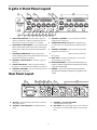
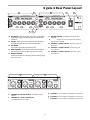
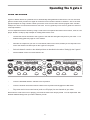
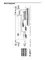
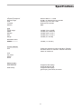
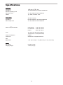
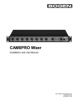
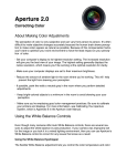
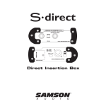
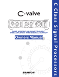
GAIN REDUCTION dB
30 24 18 12
HIGH
6
4
LINK
2
CH 2
1
CH 3
GAIN REDUCTION dB
30 24 18 12
HIGH
6
4
2
1
GAIN REDUCTION dB
30 24 18 12
HIGH
6
4
LINK
2
CH 4
1
GAIN REDUCTION dB
30 24 18 12
HIGH
6
4
2
1
POWER
ATTACK
TRIGGER
+4 20
4 CHANNEL
GATE
.1
RANGE
Hz
LOW
.3
mSec
300
.01 Sec
4
.02
Sec
5
1
KEY LISTEN
DUCKER
IN/OUT
40
Hz
LOW
+4 20
.1
-50
30
KEY
dBu +20
.3
mSec
300
.01 Sec
4
.02
Sec
5
1
dB
KEY
KEY LISTEN
DUCKER
RELEASE
HOLD
.5
RANGE
dBu +20
.3
mSec
300
.01 Sec
4
.02
Sec
5
1
dB
-50
30
KEY
KEY LISTEN
DUCKER
IN/OUT
RANGE
40
1
1
KHz 10
80
3K
RELEASE
HOLD
.5
+4 20
.1
-50
Hz
LOW
ATTACK
TRIGGER
IN/OUT
40
1
1
KHz 10
80
30
3K
ATTACK
TRIGGER
RANGE
1
1
KHz 10
dB 80
3K
RELEASE
HOLD
.5
+4 20
.1
dBu +20
ATTACK
TRIGGER
IN/OUT
40
1
1
KHz 10
-50
30
RELEASE
HOLD
.25
Hz
LOW
dBu +20
.3
mSec
300
.01 Sec
4
.02
Sec
5
1
3K
4 CHANNEL GATE
KEY
KEY LISTEN
DUCKER
dB
80
S Class Signal Processors
CH 1
Safety Instructions
Caution: To reduce the hazard of electrical shock, do not
remove cover or back.
No user serviceable parts inside. Please refer all servicing
to qualified personnel.
CAUTION
FOR CONTINUED PROTECTIO
N AGAINST RISK
OF FIRE, REPLACE ONL
Y W ITH SAME TYPE FUSE
ATT E NTION
UTILISER UN FUSI
B LE DE
RECHANGE DE M Ê ME TYPE
WAR NING
DO NOT EXPOSE
THIS EQUIPMENT
TO RAIN OR MOISTURE
RISQUE DE
AV IS
RISK OF ELECTRIC
SHOCK
DO NOT OPEN
C HO C E LE C TRONIQUE
NE PAS OU V RIR
WARNING: To reduce the risk of fire or electric shock, do not expose this unit to rain or moisture.
The lightning flash with an arrowhead symbol within an equilateral triangle, is intended to alert the user to the
presence of uninsulated "dangerous voltage" within the productʼs enclosure that may be of sufficient magnitude to
constitute a risk of electric shock to persons.
The exclamation point within an equilateral triangle is intended to alert the user to the presence of important operating and maintenance (servicing) instructions in the literature accompanying the product.
Important Safety Instructions
1.
Please read all instructions before operating the unit.
2.
Keep these instructions for future reference.
3.
Please heed all safety warnings.
4.
Follow manufacturerʼs instructions.
5.
Do not use this unit near water or moisture.
6.
Clean only with a damp cloth.
7.
Do not block any of the ventilation openings. Install in accordance with the manufacturerʼs instructions.
8.
Do not install near any heat sources such as radiators, heat registers, stoves, or other apparatus
(including amplifiers) that produce heat.
9.
Do not defeat the safety purpose of the polarized or grounding-type plug. A polarized plug has two
blades with one wider than the other. A grounding type plug has two blades and a third grounding
prong. The wide blade or third prong is provided for your safety. When the provided plug does not fit
your outlet, consult an electrician for replacement of the obsolete outlet.
10.
Protect the power cord from being walked on and pinched, particularly at plugs, convenience receptacles and at the point at which they exit from the unit.
11.
Unplug this unit during lightning storms or when unused for long periods of time.
12.
Refer all servicing to qualified personnel. Servicing is required when the unit has been damaged in
any way, such as power supply cord or plug damage, or if liquid has been spilled or objects have fallen
into the unit, the unit has been exposed to rain or moisture, does not operate normally, or has been
dropped.
2
Table of Contents
Introduction
S gate 4 Features
2
3
Controls and Functions
Front Panel Layout
Rear Panel Layout
4–5
4–5
Operating the S gate 4
Setting Up the S gate 4
Gating A Signal
Using The Filters
Using The Ducker
6
7
8
9
Dynamics Processing 101
10–11
Applications
12
System Set-ups
13–14
S gate 4 Connections
15
Block Diagrahm
16
Specifications
17–18
Copyright 2001, Samson Technologies Corp.
Printed October, 2001
Samson Technologies Corp.
575 Underhill Blvd.
P.O. Box 9031
Syosset, NY 11791-9031
Phone: 1-800-3-SAMSON (1-800-372-6766)
Fax: 516-364-3888
www.samsontech.com
1
Introduction
Congratulations on your purchase of the Samson S Gate 4! The S Gate 4 is a four channel Expander/Noise
Gate with frequency sensitive triggering, offering unparalleled control and sonic transparency impressing the
most critical listeners. Never before have so many features been packed into a single rack space unit with
four noise gates - period. The S gate 4 is a powerful tool for live sound and recording, enabling you to clean
up your mix by eliminating hums, buzzes, noisy tracks and microphone bleed. S Gate 4ʼs DFT (Dual Filter
Trigger) enables pinpoint accuracy by letting you control the exact frequency that will open the gate. A full
complement of envelope controls including Threshold, Attack, Release, Hold and Range facilitate a wide range
of applications from a subtle clean up of a vocal track, to a drastic effect like gating reverb chambers.
With proper care and adequate air circulation, your S gate 4 will operate trouble free for many years. We recommend you record your serial number in the space provided below for future reference.
Serial number:
Date of purchase:
Should your unit ever require servicing, a Return Authorization number (RA) must be obtained before shipping your unit to Samson. Without this number, the unit will not be accepted. Please call Samson at 1-8003SAMSON (1-800-372-6766) for a Return Authorization number prior to shipping your unit. Please retain the
original packing materials and if possible, return the unit in the original carton and packing materials.
2
S gate 4 Features
CH 1
GAIN REDUCTION dB
30 24 18 12
HIGH
6
4
LINK
2
CH 2
1
CH 3
GAIN REDUCTION dB
30 24 18 12
HIGH
6
4
2
1
GAIN REDUCTION dB
30 24 18 12
HIGH
6
4
LINK
2
CH 4
1
GAIN REDUCTION dB
30 24 18 12
HIGH
6
4
2
1
POWER
ATTACK
TRIGGER
+4 20
4 CHANNEL
GATE
.1
.25
RANGE
40
1
1
Hz
LOW
.3
mSec
300
.01 Sec
4
.02
Sec
5
1
KEY LISTEN
DUCKER
IN/OUT
Hz
LOW
+4 20
.1
-50
30
KEY
40
1
1
dBu +20
.3
mSec
300
.01 Sec
4
.02
5
Sec
1
dB
KEY
KEY LISTEN
DUCKER
RELEASE
HOLD
.5
RANGE
40
1
1
dBu +20
.3
mSec
300
.01 Sec
4
.02
5
Sec
1
dB
-50
30
KEY
KEY LISTEN
DUCKER
IN/OUT
RANGE
40
1
1
KHz 10
80
3K
RELEASE
HOLD
.5
+4 20
.1
-50
Hz
LOW
ATTACK
TRIGGER
IN/OUT
KHz 10
80
30
3K
ATTACK
TRIGGER
RANGE
KHz 10
dB 80
3K
RELEASE
HOLD
.5
+4 20
.1
dBu +20
ATTACK
TRIGGER
IN/OUT
KHz 10
-50
30
RELEASE
HOLD
Hz
LOW
dBu +20
.3
mSec
300
.01 Sec
4
.02
Sec
5
1
dB
80
3K
KEY
KEY LISTEN
DUCKER
The Samson S gate 4 dynamics processor utilizes the latest technology in gain management design. Here are
some of its main features:
•
Full featured, four channel Noise Gate with Expander and Ducker on each channel in a singlespace, 19" rack mount unit.
•
Extensive envelope control including Threshold, Attack, Hold and Release control for each
channel.
•
DFT (Dual FilterTrigger) for precise and predictable triggering.
•
Range control for Ducking.
•
Three stage Gate Open and Closed LED display.
•
Key input with Key Listen switch on each channel.
•
Eight Segment Gain Reduction Meter.
•
Stereo Link Switch for channels 1 & 2 and 3 & 4.
•
Advanced circuit design, utilizing low noise operational amplifiers and high quality VCAs.
•
Servo balanced inputs and outputs on XLR and 1/4" connectors.
•
High quality 41 position detent pots and backlit switches.
•
Internal Transformer.
•
Heavy-duty construction providing reliable performance session after session, performance
after performance.
•
The stylish bead blasted, electric blue anodized front-panel is as easy to read as it is to look at.
•
Three-year extended warranty.
3
S gate 4 Front Panel Layout
3
2
1
4
CH 1
ATTACK
TRIGGER
+4 20
.1
12
1
2
3
4
5
6
13
Hz
LOW
RANGE
40
.3
mSec
300
.07 Sec
.02
4
Sec
5
0
15
16
DUCKER
KEY LISTEN
17
18
19
20
7
8
9
10
11
12
13
B
C
D
Hz
LOW
dBu +20
.3
mSec
300
.01 Sec
4
.02
Sec
5
0
KHz 10
dB 100
3K
-50
30
KEY
DUCKER
KEY LISTEN
F
S.GATE 4
CH 3
KEY
BALANCED
OUTPUT
INPUT
BALANCED
OUTPUT
INPUT
C
D
CHANNEL 4, 1/4” TRS LINE INPUT 1/4” TRS Balanced line input.
KEY INSERT -The gate trigger signal can be external
processed, or an external key signal can be inserted
here.
Hz
LOW
G
CH 4
4
TRIGGE
40
1
1
CHANNEL 3 CONTROLS - The same knob and switch
complement as Channel 1.
STEREO LINK SWITCH (3 & 4)-When engaged, channel 4 functions are controlled by the settings on channel 3.
CHANNEL 4 CONTROLS - The same knob and switch
complement as Channel 1.
MAINS POWER SWITCH - When turned on, activates
the S gate 4.
RACK EARS - Used for mounting into a 19 inch standard rack. (One on each side.)
LOW FILTER CONTROL - Used to set the lower frequency at
which the 12dB cut is applied to the side chain input, covering
a range from 30Hz to 3KHz.
TRIGGER – Used to set the minimum signal level that the
Gate/ Ducker circuit begins to function in a range from –60 to
+10 dB.
KEY
B
HIGH
RANGE
21
E
AC INLET - IEC standard AC power cable connector
with external fuse.
CHANNEL 4, XLR LINE INPUT - XLR Balanced line
input.
1
.1
-50
IN/OUT
2
RELEASE
HOLD
.25
6
KHz 10
dB 100
30
KEY
Rear Panel Layout
A
+4 20
.1
dBu +20
ATTACK
TRIGGER
IN/OUT
CH 3
GAIN REDUCTION dB
30 27 24 18 12
HIGH
3K
14
CH 2
1
1
1
HIGH FILTER CONTROL - Used to set the upper frequency at which the 12dB cut is applied to the side
chain input, covering a range from .1 to 10 KHz.
GATE OPEN & CLOSED METER – Three segment LED
Meter indicating the GATE status. Green when Open,
Yellow when approaching threshold and Red when
closed.
GAIN REDUCTION METER – Eight segment LED
meter displaying the amount of Gain Reduction when
Expander/Gate circuit is activated.
CHANNEL 1 IN/OUT SWITCH – Activates S gate 4’s
Channel 1.
STEREO LINK SWITCH - When engaged Channel 2
functions are controlled by the settings on Channel 1.
CHANNEL 2 CONTROLS - The same knob and switch
complement as Channel 1.
A
LINK
2
RELEASE
HOLD
.25
6
KHz 10
-50
30
6
GAIN REDUCTION dB
30 27 24 18 12
HIGH
4 CHANNEL
EXPANDER
GATE
5
3K
dBu +
S gate 4 Rear Panel Layout
7
CH 3
ION dB
6
2
1
GAIN REDUCTION dB
30 27 24 18 12
HIGH
6
LINK
2
10
CH 4
1
11
GAIN REDUCTION dB
30 27 24 18 12
HIGH
6
2
1
POWER
ELEASE
2
9
8
40
5
DUCKER
Hz
LOW
dBu +20
.3
mSec
300
.07 Sec
4
.02
Sec
5
0
KEY LISTEN
DUCKER
-50
22
IN/OUT
Hz
LOW
dBu +20
mSec
E
F
.01 Sec
4
.02
Sec
5
0
dB 100
DUCKER
KEY LISTEN
19 DUCKER SWITCH – Configures the channel for
Ducking.
20 RANGE – Adjusts the level of maximum attenuation, from 0 to 100dB.
21 CHANNEL 2 IN/OUT SWITCH- Activates S gate 4’s
Channel 2.
22 CHANNEL 3 IN/OUT SWITCH- Activates S gate
4’s Channel 3.
23 CHANNEL 4 IN/OUT SWITCH- Activates S gate
4’s Channel 4.
I
CH 1
KEY
BALANCED
OUTPUT
BALANCED
OUTPUT
INPUT
300
23
CH 2
BALANCED
OUTPUT
.3
KEY
H
KEY
40
3K
14 KEY SWITCH – When engaged the Key insert is enabled allowing the trigger signal to be externally processed or externally
controlled.
15 ATTACK - Adjusts the amount of time, from .3 to 300 miliseconds, that the Gate/Ducker takes to become fully open.
16 KEY INSERT
INSERT– TRS Send and Return allowing for external control and processing of the channel’s Side Chain.
17 HOLD CONTROL - Used to set the amount of time before the
gate starts to close with a variable range of .01 to 4 seconds.
18 RELEASE CONTROL - Adjusts the length of time the gate takes
to return to the level set on the Range control covering a range
of .02 to 5 seconds.
CH 3
RANGE
1
1
KHz 10
dB 100
30
RELEASE
HOLD
.25
+4 20
3K
KEY
ATTACK
TRIGGER
IN/OUT
40
.1
-50
30
RANGE
1
1
KHz 10
dB 100
0
RELEASE
HOLD
.25
+4 20
.1
Sec
ATTACK
TRIGGER
RANGE
1
INPUT
CHANNEL 4, XLR LINE OUTPUT - XLR Balanced line
output.
CHANNEL 4, 1/4” TRS LINE OUTPUT 1/4” TRS Balanced line output.
5
G
CHANNEL 3 - Same Inputs and Outputs as Channel 4.
H
CHANNEL 2 - Same Inputs and Outputs as Channel 4.
I
CHANNEL 1 - Same Inputs and Outputs as Channel 4.
Operating The S gate 4
Whether you are an experienced audio engineer, just starting out, or you just want to experiment, follow the steps
below to get going. Further sections in this manual will cover basic dynamics and the associated parameters, system set-ups and applications for using dynamics processing in recording and live sound applications.
SETTING UP THE S gate 4
• Connect one set of inputs and outputs to the Channel 1 connectors on the rear panel. If possible, use your
mixer insert points to connect the S gate 4. For a detailed wiring, guide see page 16 in this manual.
• Set the controls to the following positions:
CH 1
GAIN REDUCTION dB
30 27 24 18 12
HIGH
ATTACK
TRIGGER
+4 20
4 CHANNEL
EXPANDER
GATE
.1
RANGE
Hz
LOW
.3
mSec
300
.07 Sec
4
.02
Sec
5
0
+4 20
-50
30
KEY LISTEN
HIGH FILTER CONTROL - .1
LOW FILTER CONTROL - 30
TRIGGER CONTROL - -60
KEY SWITCH - OUT
ATTACK CONTROL - 20
KEY LISTEN - OUT
KHz 10
dB 100
3K
KEY
DUCKER
IN/OUT
Hz
LOW
dBu +20
.3
mSec
300
3K
HOLD CONTROL - .5
RELEASE CONTROL - .5 SEC
DUCKER SWITCH - OUT
RANGE CONTROL - 80
IN/OUT - OUT
In this configuration, the S gate 4 is simply passing audio at unity gain with no dynamics processing. It is a good
idea to check your gain structure at this point. Use the Gain Reduction meter to match the level.
•
Send a signal to the S gate 4ʼs inputs.
•
Look at the GAIN REDUCTION meter and confirm that no LEDʼs are illuminated.
•
Press the IN/OUT switch on and off and listen to the signal. You should hear no change in level.
6
ATTACK
TRIGGER
IN/OUT
40
.1
dBu +20
3
HIGH
1
1
CH 2
1
KHz 10
-50
30
LINK
2
RELEASE
HOLD
.25
6
KEY
KEY L
Operating The S gate 4
GATING A SIGNAL
Unwanted noises, buzzes and hisses can be easily removed by using S gate 4. The idea is to have the Gate
open only when the sound you want to hear is playing and to mute off and eliminate (Gate closed) the unwanted
noises, buzzes and hisses.
Below is a step by step example on gating a signal with the S gate 4. A CD with a sample of a snare drum hit with
reverb, or a drum machine is a good signal source for the purpose of this test example, however you can use any
audio source. To Gate your signal, do the following:
Follow the previous section, "SETTING UP THE S gate 4" for normalizing the controls.
•
To engage the Gate, make sure that the IN/OUT switch is pressed in and that the green LED is illuminated.
•
Now with your sound source playing, increase the TRIGGER level and listen as the signal begins to gate.
NOTE: For a visual representation of the
gate activity, look at the GATE OPEN/
CLOSED DISPLAY located above the
TRIGGER control. The display has three
LED segments indicating gate open, hold
time and gate closed.
GREEN - GATE OPEN
RED - GATE CLOSED
YELLOW - HOLD
CH 1
GAIN REDUCTION
30 27 24 18 12
HIGH
ATTACK
TRIGGER
+4 20
•
.1
RELE
HOLD
.5
6
1
KHz 10
To get the gate to operate fast, smoothly
and predictably use the ATTACK, HOLD and RELEASE controls to contour the shape.
-60
dBu +10
.3
mSec
300
.04 Sec
In theory, the ideal gate settings would open the gate as fast as possible when the desired signal is on and close
the gate as fast as possible when the desired sound is off. The problem is that when the gate is opening and
Hz you
30noise
3K are trying to remove. This results in unwantclosing, it is putting a new envelope on the hiss, buzz and
LOW
ed sounds like pops and zips. DONʼT SWEAT! You can get rid of these unwanted FILTER
noise artifacts
by adjusting
KEY
LISTEN the
ATTACH, HOLD and RELEASE controls.
In order to get the best results, the S gate 4ʼs envelope controls include a HOLD time control. HOLD time is
especially useful since it lets you set the ATTACK and RELEASE to faster times. Generally, you can set faster
ATTACK and RELEASE times on sounds with fast attacks, such as drums. On sounds with slow attacks, such
as strings and synthesizer pads, slow ATTACK and RELEASE times will sound much smoother. You can also
change the characteristic of a sound such as using a slow attack and quick release to change an electric bass
into a synthesizer bass.
Keep in mind that all the controls including TRIGGER are somewhat interactive, so experimentation is the best
way to get the sound youʼre looking for. Remember to use your ears, because if it sounds good to you, it more
than likely sounds good.
7
4
.2
Se
Operating The S gate 4
USING THE FILTERS
The S gate 4 employs a DFT (Dual Filter Trigger) circuit which allows you to create an equalization contour on
the trigger filter. The DTF is a two-stage, band-pass equalizer on the trigger or side-chain input. The filters are
applied to the trigger whether it is derived from the audio input, or by the KEY input. By using the DTF, you can
dial in and out the exact frequency range that you want to influence the opening and closing of the gate. This is
especially useful when gating drums, since you often have a lot of microphone bleed due to close placement and
the high SPL of the wood hitting the skin. By using the DFT, you can contour the trigger on each of S gate 4ʼs
channels to open the gate when it detects the frequency set on the High and Low Filter controls. Follow the steps
below to use the DFT to set the gate to turn a music track into a bass drum only track.
•
Connect the first two channels of the S gate 4 to the main left and right insert points of your mixer. For a
detailed wiring guide see page 16 of this manual.
•
Set both channelʼs controls to the default positions as described in the section "Setting Up the S gate 4".
•
Press channel one and twoʼs IN/OUT switches to the IN position and engage the LINK switch.
•
Play some music from a sound source (such as a CD player) into two channels of your mixer. For this
experiment you should use a recording with a contemporary, up-front drum track.
•
Set the High filter control to the 9:00 position which is 250 Hz.
You should immediately hear the bass drum breaking through the gate. By engaging the filter you have
just created an EQ curve with a band pass of 30Hz to 250Hz on the gateʼs trigger detector. The result is
only the low energy from the kick drum will cause the gate to trigger open. You can use the TRIGGER,
ATTACK, HOLD and RELEASE to fine-tune and dial in just the sound of the kick drum.
Note: You can hear the effect of the DFT circuit on the trigger or side-chain input by pressing the KEY
LISTEN switch. When engaged, the KEY LISTEN circuit routes the trigger signal to the audio output
allowing you to hear what effect the filters have on the side-chain.
The example below shows a typical set up for using DFT while gating drum microphones.
Kick Drum with the filter
set on 30Hz and 200Hz.
LINK
CH 2
ATTACK
TRIGGER
IN/OUT
0
+4 20
.1
30
2
1
RELEASE
HOLD
.5
6
40
Hz
LOW
+4 20
.1
dBu +20
.3
mSec
300
.04 Sec
4
.2
Sec
2
1
3K
dB
KEY LISTEN
DUCKER
LINK
2
RANGE
Hz
LOW
dBu +20
.3
mSec
300
.04 Sec
4
.2
Sec
2
1
dB
+4 20
-50
30
8
KEY LISTEN
DUCKER
IN/OUT
HOLD
.5
1
KHz 10
60
3K
KEY
ATTACK
TRIGGER
IN/OUT
40
.1
-50
GAIN RED
30 27 24 18
HIGH
1
1
CH 4
1
RELEASE
HOLD
.5
6
KHz 10
60
30
KEY
ATTACK
TRIGGER
RANGE
1
1
Floor Tom with the filter
set on 80Hz and 500Hz.
GAIN REDUCTION dB
30 27 24 18 12
HIGH
KHz 10
-50
IN/OUT
CH 3
GAIN REDUCTION dB
30 27 24 18 12
HIGH
Rack Tom with the filter set on 250Hz and
800Hz.
Snare Drum with the filter
set on 1KHz and 2KHz.
Hz
LOW
dBu +2 0
.3
mSec
300
.04 Sec
3K
KEY
KEY LISTEN
4
ANNEL
NDER
ATE
Operating The S gate 4
USING THE DUCKER
S gate 4ʼs Ducker feature is a powerful tool for automatically mixing different sound sources. You can use the S
gate 4ʼs Ducker when you want one signal to control the level of another channel or channels. One of the most
popular examples of using a ducker is when you have a voice-over turn down a music program track. Another
example is to have a vocal track turn down a solo track. This is a great way to mix a sax or guitar solo around a
vocal improvisation.
You can experiment with the ducker by using a vocal track or microphone and stereo sound source, such as a CD
player. Below is a step by step example on ducking music with a vocal.
•
Connect the first two channels of the S gate 4 to the main left and right insert points of your mixer. For a
detailed wiring guide see page 16 of this manual.
•
Now take an output from your mic or vocal channel, either from a direct, auxiliary or bus output and connect to the channel one KEY input on the S gate 4ʼs rear panel.
•
Set both channelʼs controls to the default positions as described in the section "Setting Up the S gate 4".
•
Set the RANGE control on both channels to 40.
CH 1
GAIN REDUCTION dB
30 27 24 18 12
HIGH
ATTACK
TRIGGER
+4 20
.1
RANGE
40
+4 20
.1
Hz
LOW
dBu +20
.3
mSec
300
.07 Sec
4
.02
Sec
5
0
DUCKER
IN/OUT
1
HIGH
TRIG
RANGE
40
1
1
.1
-50
30
KEY LISTEN
2
RELEASE
HOLD
.25
6
KHz 10
dB 100
3K
KEY
ATTACK
TRIGGER
IN/OUT
CH 3
GAIN REDUCTION dB
30 27 24 18 12
HIGH
1
1
CH 2
1
KHz 10
-50
30
LINK
2
RELEASE
HOLD
.25
6
Hz
LOW
dBu +20
.3
mSec
300
.01 Sec
4
.02
5
Sec
0
dB 100
3K
KEY LISTEN
DUCKER
•
Press the DUCKER and KEY switches to the IN position.
•
Press the channel one and two IN/OUT switch to the IN position and engage the LINK switch.
•
Play some music from a sound source (such as a CD player) into two channels of your mixer.
Now when the vocal track or mic is playing, youʼll hear the music track drop by 40 dB. You can experiment with
different RANGE settings until you find the balance you like.
9
-50
30
KEY
KHz 10
Hz
LOW
3K
d
Dynamics Processing 101
To begin to understand dynamics processing, we must first understand what dynamics are. Dynamics, or the
dynamic range of a signal or audio device, is the amount of level between the softest and loudest possible output. Dynamics processing is applied to a signal to manage the changes in level. Various types of processing
units are available to control dynamics including Noise Gates, Expanders, Compressors, Limiters and De-Essers.
All of these processes have a unique effect on a signal, but one common element they share is that in one way or
another they control gain. Some dynamics processors control gain in a subtle way by slightly reducing how soft
and loud a signal is, while others make drastic changes in gain like reducing the signal until itʼs off. Applications
for dynamics processing can be categorized by two distinct groups; first, to treat a signal that has an unpredictable dynamic range and make it predictable, and second, to create a "sound" by squeezing out the dynamic
range. Whether used for a live sound application, recording, mixing or mastering, dynamic processors like the S
gate 4 are valuable tools for controlling gain. The following is a basic overview of dynamics processing and how it
is used to improve the quality of recorded and live sound.
COMPRESSOR
A good compressor is one of the most useful tools in live sound and recording. Compressors are used to control
the dynamic range of a signal, which offers a variety of benefits including leveling a signal thatʼs being recorded,
having an instrument sit in the mix, and increasing the loudness of a sound system to name a few. Drastic
amounts of compression will also result in an effect that becomes more of a sound, than just controlling gain. To
understand how a compressor works, it is necessary to become familiar with the basic parameters which include
threshold, ratio, attack time, and release time.
Threshold
Threshold is the level that once the signal exceeds, gain reduction is applied. The normal range of adjustment for
the threshold level is –40 to +20 dBu. If the threshold level is set above the highest level of the signal being sent
to the compressors, the gain reduction is never triggered. Therefore, the compressor is virtually by-passed. If
the threshold level is set very low so that any signal will trigger gain reduction, the compressor is working as an
automatic leveler.
Ratio
The ratio control is used to set the proportion of gain reduction in relationship to the input signal. For example if
the ratio is set to 2:1 and the signal crosses above the threshold level, an increase in level of 2 dB will produce a
1 dB increase in level at the output. A ratio setting of ∞ to 1 means that an infinite amount of input signal is needed to raise the output level by 1 dB. This means that the output level stays constant even when the input crosses
over the threshold level.
Attack Time
Attack time is the amount of time that a compressor takes to effect the gain reduction after the signal rises above
the threshold level. A well-designed compressor has adjustable attack times ranging from 100 µs (microseconds)
to 150 ms (milliseconds). A good compressor will sound smooth as it begins to control the gain regardless of the
attack time.
Release Time
The release time is set to control how long the compressor takes to return the input signal back to its original level
once the signal falls below the threshold level. The acceptable range for release time is from 500µs to 5 seconds.
In normal use, faster release times are used for spoken word and longer release times are generally better for
instrumental music.
10
Dynamics Processing 101 - Continued
Soft-Knee / Hard-Knee
In order to prevent harsh, unnatural envelopes on compressed signals, sophisticated dynamics processors like
the S gate 4 feature an SKD (Smart Knee Detector) or automatic knee circuit. The Smart Knee Detector automatically switches from Soft-Knee when the signal is less than 10 dB over Threshold, to Hard-Knee when the
signal is 10db above Threshold. In Soft-Knee mode, there is a gradual effect on gain change, which begins as the
signal approaches the Threshold level. In Hard-Knee mode, gain reduction is linear based on the Threshold and
Ratio controls. Any signal that falls below the Threshold level will be unprocessed.
Noise Gates
Noise gates are used to remove unwanted noise and/or bleed from recorded tracks in the studio or from open
microphones in live sound systems. Noise gates can also be used as a sound effect, most commonly to chop the
end of a reverb, letʼs say on a snare drum, so that the entire snare sound ends just before the beat. The basic
principle of a noise gate is to work as an automatic mute switch. Mute off (Gate Open) when the desired signal
is present and mute on (Gate Closed) when the desired signal is not present. In order to get the gate to work
predictably, it is necessary to set a threshold, or trigger level that will determine when the gate will open. If the
signal is below the trigger, the gate will remain closed. When the signal is above the trigger, the gate will trigger
open allowing the desired signal to pass and be heard. Noise gates often have other adjustable controls like
attack, hold, range and release. Many noise gates like the S gate 4 use sophisticated circuits to control some of
these parameters automatically.
Downward Expander
The purpose of a well-designed Downward Expander is to increase the perceived dynamic range of a system.
This is accomplished by decreasing the gain during the softer sections, thereby lowering the relative noise floor.
When the signal level is below the desired trigger level, the expander lowers the overall gain by the selected
amount.
Limiter
A Limiter is a specific form of a compressor configured to prevent peaks and for general overload protection. It is
often characterized by a high ratio setting (10 or above), as well as a relatively high threshold level.
Stereo Link Mode
The S gate 4 can be configured from dual-mono operation to stereo by using the Stereo Link switch. In Stereo
Link mode, Channel 2 functions are controlled by the settings of Channel 1 with the exception of IN/OUT, KEY
and LIMITER. The same holds true for Channels 3 and 4.
11
Applications
Using the Expander/Gate to Remove Hiss and Noise
The S gate 4 is an extremely useful tool in reducing the level of unwanted noises. By using the Expander/Gate
you can effectively fade the noise into the noise floor or abruptly turn the unwanted signal completely off.
Letʼs say you want to reduce the bleed or cross talk that occurs when different instruments are recorded in close
proximity to each other. You have recorded an acoustic guitar simultaneously in the same room as with some
other acoustic instruments. The problem is that you hear a lot of the other instruments playing when the acoustic
guitar is silent. This can cause phasing and comb filtering problems due to microphone placement, so having
the bleeding signal drop into the noise floor is desirable. To do this, set the S gate 4 to Expander mode with the
Release switch to Slow and adjust the Trigger so that the acoustic guitar signal is well above the threshold level.
When the signal from the acoustic guitar track falls below the threshold level, the signal subtly fades into the
noise floor.
Now letʼs say youʼre attempting to remove the pick-up noise and hum from a guitar track that was recorded
through a loud amplifier. The hum and noise is most noticeable in-between the rhythm of the performance, so you
want to have the gate close during the silent parts and open during the musical passages. To do this, set the S
gate 4 to Gate mode and adjust the Trigger level so that the gate is open just during the musical guitar parts, and
so that the gate is closed during the silent passages so that the hum and noise is muted.
Gating Drums
Using noise gates on drums is particularly useful in recording and in live sound. When a drum kit is set up with
individual microphones on each drum in a live PA system, thereʼs potential for great sound. However, there are
several gain management problems that can occur. Several microphones, like the ones on the tom-toms, will
only be used occasionally and until the time that the tom-tom is actually played, its microphone is merely picking
up unwanted sound from other instruments on stage. This adds a lot of unwanted mush in the mix and also adds
to feedback problems. Set the controls so that the gate opens only when the tom-tom is played. This same technique is useful on drums that have been recorded on individual tracks. By using the Gate to mute the bleed of
the other drums, you can effectively reduce the comb filtering produced by phase cancellation due to microphone
proximity.
Gating Longer Sounds
When using a noise-gate on sounds with a longer decay such as a piano, it is usually necessary to use a longer
release time. Run the piano signal through the S gate 4 and set the Expander/Gate Release switch to Slow.
Adjust the Trigger level on sustained passages to get the best results. Be sure to listen for the natural decay of
the instrument and allow the gate to remain open until just after the end of the decay.
Using a Noise Gate to Tighten Up the Mix
Using a Noise Gate to Tighten Up the Mix
S gate 4 can be used in mixing to clean up loosely played tracks, and even make a rhythm section sound tighter
than they really are. On a single instrument, like a rhythm guitar track, you can clean up the performance by gating the track. To do this, set a release time to exactly match the tempo of the music, so that you hear the guitar
playing, but stopping (gate closed) just before the beat. By doing this, a less than perfect rhythm track can quickly
sound like it was played by a great session guitarist. Also, pay attention to the space that the S gate 4 creates in
the track, since very often a great performance really jumps out when it is framed by the space, or silence around
the track.
To tighten up a group of instruments, patch in an S gate 4 channel on each instrument and dial in a good gate
setting on each. Now select the best performance from the group that you want to use as a master to control
the other instruments. Take the KEY OUTPUT from that channel and patch it into each the other channelʼs KEY
INPUT. The result is that the audio (performance and rhythm) from the master channel will key other channelʼs
gates to open and close so that the performance of all channels sounds exactly the same.
12
S gate 4 System Set-Ups
LIVE SOUND SYSTEM WITH GATES ON INDIVIDUAL CHANNELS
INPUT
MIC/LINE 3
MIC/LINE 4
Channel 1
Insert Cable
Channel 2
Insert Cable
MIC/LINE 2
Return
Return
Channel 3
Insert Cable
Send
Return
Channel 4
Insert Cable
BALANCED
OUTPUT
INPUT
INPUT
MIC/LINE 1
CH 1
KEY
BALANCED
OUTPUT
Return
INPUT
Send
CH 2
KEY
BALANCED
OUTPUT
Send
S.GATE 4
CH 3
KEY
BALANCED
OUTPUT
Send
CH 4
KEY
MIC/LINE 5
MIC/LINE 6
MIC/LINE 7
MIC/LINE 8
LINE
LINE
LINE
LINE
LINE
LINE
LINE
LINE
INSERT
INSERT
INSERT
INSERT
INSERT
INSERT
INSERT
INSERT
MIC/LINE 9
MIC/LINE 11
MIC/LINE 10
MIC/LINE 13
MIC/LINE 14
MIC/LINE 12
MDR 16
MIC/LINE 15
1
INSERT
2
3
INSERT
4
INSERT MIX
1
OUTPUTS
2
1
AUX OUT
2
L
CR
R
3
OUTPUTS
4
L
AUX RET1
R
L
AUX RET2
R
L
MIX
R
MONO
MIC/LINE 16
MONO L
5
0
PEAK
30
PEAK
30
PEAK
30
GAIN
GAIN
PEAK
30
GAIN
PEAK
30
GAIN
Mixer Insert
Points
5
5
60
-26
+26
HF
5
10
0
5
5
12K
10
15
MID
5
60
5
+26
-26
HF
5
10
0
5
60
-26
HF
5
0
5
60
-26
HF
5
0
5
MID
5
60
0
30
GAIN
5
+26
-26
HF
5
10
0
5
15
60
GAIN
5
+26
-26
HF
5
10
0
5
15
5
GAIN
60
5
+26
-26
HF
5
10
0
5
+26
HF
5
0
5
15
0
12K
5
15
10
15
500
0.3
10
10
15
15
Fc
1K
500
0.3
10
15
10
15
Fc
1K
500
0.3
10
15
10
15
Fc
1K
500
0.3
15
10
10
15
Fc
1K
500
0.3
15
10
10
15
Fc
1K
500
0.3
15
10
10
10
15
Fc
1K
500
0.3
15
500
3K
0.1
0
LF
5
15
3K
0.1
5K
5
15
10
.15
0
LF
5
15
10
0.1
LF
5
3K
.15
5K
15
10
.15
LF
5
3K
0.1
5K
15
10
.15
3K
0.1
5K
LF
5
15
10
3K
.15
0.1
5K
LF
5
15
10
0.1
LF
5
AUX 2
0
PAN
0
80Hz
LEFT
10
0
5
RIGHT
0
5
AUX1
12K
10
15
5
LEFT
HF
5
10
15
65
AUX
0
10
0
5
10
12K
10
15
80Hz
LEFT
HF
5
PAN
LF
LEFT
HF
5
12K
10
0
5
80Hz
0
16
125
10
POST
0
10
POST
0
10
POST
0
10
POST
0
10
POST
0
10
POST
0
10
POST
0
10
POST
15
15
15
15
15
AUX 1
5
5
AUX2
5
AUX2
DSP
5
AUX2
DSP
5
AUX2
DSP
5
AUX2
DSP
5
AUX2
DSP
DSP
1K
2K
4K
EQ IN/OUT
EQ TO AUX
16K
6K
AUX RETURN 2
5
5
SOLO
0
10
+48V
PO
SOLO
P
SOLO
0
10
10
5
5
15
AUX 1
AUX 2
5
+20
AUX 2
5
AUX
AUX
16K
6K
80Hz
AUX 1
AUX 2
5
AUX
AUX2
DSP
4K
LF
5
15
AUX 1
AUX 2
5
5
AUX2
DSP
2K
15
10
15
500
250
AUX RETURN 1
5
0
500
250
+15dB
12
9
6
3
0dB
3
6
9
12
-15dB
65
12K
10
5
125
HF
5
15
80Hz
10
RIGHT
10
LF
5
0
5
14
15
10
10
10
RIGHT
10
15
15
5
0
5
12
1K
L 2TK OUT R
+15dB
12
9
6
3
0dB
3
6
9
12
-15dB
10
PAN
RIGHT
10
LF
5
0
5
10
R
AUX 2
5
10
PAN
2TK IN
AUX 1
AUX
10
L
2T TO MIX
80Hz
10
LF
5
AUX1
5
15
AUX 2
5
AUX
DIGITAL EFFE
LF
5
AUX 1
AUX 2
5
AUX
15
15
10
AUX 2
12K
10
0
15
80Hz
10
HF
5
15
5K
15
10
5
AUX1
0
5
15
80Hz
10
5
15
10
5
10
LF
5
15
80Hz
10
0
13
15
AUX 1
10
3K
.15
5K
15
10
5
AUX1
0
5
15
80Hz
10
5
AUX1
0
5
15
80Hz
10
5
AUX1
0
5
15
80Hz
10
5
AUX1
0
5
15
80Hz
10
5
AUX1
0
5
15
80Hz
10
5
3K
0.1
5K
5
15
80Hz
10
.15
5
15
12K
10
0
Fc
0
.15
LF
5
HF
5
15
15
1K
0.3
5
10
AUX 1
10
15
Fc
1K
0
11
15
10
AUX 2
12K
10
0
15
80Hz
10
HF
5
15
5
10
5
10
LF
5
10
MID
5
0
9
15
15
12K
10
15
MID
HF
5
10
15
60
10
15
5
0
5
12K
10
15
MID
5
0
5
12K
10
15
MID
5
0
5
12K
10
15
15
0
5
12K
10
15
MID
5
+26
10
15
5
0
5
12K
10
15
MID
5
+26
10
15
5
0
5
12K
10
15
15
0
24 DS
PEAK
30
GAIN
10
0
BIT
PEAK
PEAK
30
5
-26
AUX
0
DSP
DSP 1-2
10
0
DSP 3-4
10
0
+9
DSP ON
10
DSP AUX1
+6
PEAK
+3
0
10
0
PAN
10
0
PAN
10
0
PAN
10
0
PAN
10
0
PAN
10
0
PAN
10
0
PAN
0
10
10
0
10
PAN
PAN
0
10
PAN
0
10
PAN
0
1
PAN
8
2
7
LEFT
RIGHT
LEFT
RIGHT
LEFT
RIGHT
LEFT
RIGHT
LEFT
RIGHT
LEFT
RIGHT
LEFT
RIGHT
LEFT
RIGHT
LEFT
RIGHT
LEFT
RIGHT
LEFT
RIGHT
LEFT
RIGHT
-3
3
6
-6
-9
4
5
SOLO
SOLO
SOLO
SOLO
SOLO
SOLO
SOLO
SOLO
SOLO
In this example, the S gate 4 is inserted on the mixer’s first four input channels.
SOLO
SOLO
SOLO
SOLO
DIGITAL EFFECTS
1 LARGE HALL
5 VOCAL RM.2
2 MEDIUM HALL 6 CHORUS+REVERB
3 LARGE ROOM 7 CHORUS+DELAY
4 VOCAL RM.1 8 STAIRWELL
SOLO
-12
-16
-18
SOLO/PFL
-21
BUS
1-2
BUS
1-2
BUS
1-2
BUS
1-2
BUS
1-2
BUS
1-2
BUS
1-2
BUS
1-2
BUS
1-2
BUS
1-2
BUS
1-2
BUS
1-2
BUS
3-4
BUS
3-4
BUS
3-4
BUS
3-4
BUS
3-4
BUS
3-4
BUS
3-4
BUS
3-4
BUS
3-4
BUS
3-4
BUS
3-4
BUS
3-4
1-2 TO MIX
3-4 TO MIX
MIX MUTE
SOLO DEFEAT
MIX
2T
10
10
10
10
10
10
10
10
10
10
10
10
10
10
5
5
5
5
5
5
5
5
5
5
5
5
5
5
0
0
0
0
0
0
0
0
0
0
0
0
0
0
5
5
5
5
5
5
5
5
5
5
5
5
5
5
10
10
10
10
10
10
10
10
10
10
10
10
10
10
20
20
20
20
20
20
20
20
20
20
20
20
20
20
30
30
30
30
30
30
30
30
30
30
30
30
30
30
40
40
40
40
40
40
40
40
40
40
40
40
40
40
50
50
50
50
50
50
50
50
50
50
50
50
50
50
60
60
60
60
60
60
60
60
60
60
60
60
60
60
CHANNEL 9-10
CHANNEL 11-12
CHANNEL 13-14
CHANNEL 15-16
10
SOLO
5
5
CHANNEL 2
CHANNEL 3
CHANNEL 4
CHANNEL 5
CHANNEL 6
13
CHANNEL 7
CHANNEL 8
1
OUTPUTS
2
3
OUTPUTS 4
10
5
10
20
30
0
CHANNEL 1
5
0
0
C/ROOM
+PHONES
10
40
50
60
PHONES
L
MIX
S gate 4 System Set-Ups
LIVE SOUND SYSTEM WITH GATES ON SUB INSERT POINTS
CH 2
KEY
INPUT
Return
INPUT
Channel 2
Insert Cable
Send
Return
Send
Channel 3
Insert Cable
Send
Return
INPUT
Channel 4
Insert Cable
BALANCED
OUTPUT
Channel 1 v
Insert Cable
INPUT
CH 1
KEY
BALANCED
OUTPUT
BALANCED
OUTPUT
Return
S.GATE 4
CH 3
KEY
BALANCED
OUTPUT
Send
CH 4
KEY
SUB INSERTS
MIC/LINE 1
MIC/LINE 2
MIC/LINE 3
MIC/LINE 4
MIC/LINE 5
MIC/LINE 6
MIC/LINE 7
MIC/LINE 8
MIC/LINE 9
MIC/LINE 11
MIC/LINE 13
1
LINE
LINE
LINE
LINE
LINE
LINE
LINE
LINE
MIC/LINE 10
MIC/LINE 14
MIC/LINE 12
MDR 16
MIC/LINE 15
INSERT
2
3
INSERT
INSERT MIX
4
L
1
OUTPUTS
2
1
AUX OUT
2
L
CR
R
3
OUTPUTS
4
L
AUX RET1
R
L
AUX RET2
R
MIX
R
MONO OUT
MIC/LINE 16
MONO LEVEL
INSERT
INSERT
INSERT
INSERT
INSERT
INSERT
INSERT
5
INSERT
0
PEAK
30
PEAK
30
PEAK
30
GAIN
GAIN
PEAK
30
GAIN
PEAK
30
GAIN
5
-26
0
5
60
-26
+26
HF
5
10
12K
10
15
0
5
MID
5
5
+26
-26
HF
5
10
0
5
12K
60
-26
HF
5
0
5
12K
60
-26
HF
5
0
5
15
60
0
30
GAIN
5
+26
-26
HF
5
10
0
5
MID
5
60
GAIN
5
+26
-26
HF
5
0
5
MID
5
5
+26
-26
HF
5
12K
5
15
MID
HF
5
0
5
0
10
10
15
500
10
15
15
Fc
1K
0.3
10
500
0.3
10
15
10
15
Fc
1K
500
0.3
10
15
10
15
Fc
1K
500
15
10
15
Fc
1K
0.3
10
500
15
10
15
Fc
1K
0.3
10
500
15
10
15
Fc
1K
0.3
10
500
15
500
3K
0.1
0
LF
0
5
80Hz
10
15
3K
0.1
5K
5
5
10
.15
LF
5
15
.15
5K
15
LF
3K
15
LF
3K
LF
3K
.15
LF
5
15
DIGITAL EFFECTS
0
10
PAN
0
80Hz
LEFT
10
0
5
RIGHT
12K
10
15
0
15
15
10
15
15
10
10
12K
10
0
65
15
15
10
10
16
125
10
POST
0
10
POST
0
10
POST
0
10
POST
0
10
POST
0
10
POST
0
10
POST
0
10
POST
AUX 1
5
5
AUX2
5
AUX2
DSP
5
AUX2
DSP
5
AUX2
DSP
5
AUX2
DSP
5
AUX2
DSP
AUX 2
5
5
AUX2
DSP
DSP
15
15
10
2K
4K
EQ IN/OUT
EQ TO AUX 1
16K
6K
POWER
+48V
5
SOLO
SOLO
SOLO
80Hz
0
10
0
10
PFL
10
5
5
AUX 1
AUX 2
5
+20
AUX 2
5
AUX
AUX
1K
AUX RETURN 2
5
LF
5
AUX 1
AUX 2
5
AUX
AUX2
DSP
AUX 1
500
250
AUX RETURN 1
5
0
16K
6K
15
5
80Hz
4K
+15dB
12
9
6
3
0dB
3
6
9
12
-15dB
65
12K
10
0
500
250
HF
5
15
125
+15dB
12
9
6
3
0dB
3
6
9
12
-15dB
RIGHT
10
LF
5
0
5
14
15
5
80Hz
LEFT
HF
5
15
2K
AUX 2
10
PAN
RIGHT
10
LF
5
0
5
12
15
0
5
80Hz
10
12K
10
15
LF
5
LEFT
HF
5
10
1K
L 2TK OUT R
AUX 1
AUX
0
PAN
RIGHT
0
5
10
15
5
AUX1
LEFT
HF
5
10
5
R
15
5
10
PAN
2TK IN
10
15
AUX 2
AUX
Fc
10
L
2T TO MIX
80Hz
AUX 1
5
AUX
15
LF
5
10
AUX 2
12K
10
15
LF
5
15
AUX1
15
HF
5
0
5
5K
15
10
5
AUX1
0
5
80Hz
10
LF
80Hz
10
15
5
15
5
AUX 2
5
0
13
10
AUX 1
AUX 2
3K
0.1
5K
5
10
15
15
AUX1
0
5
80Hz
10
5
.15
0.1
5K
5
10
15
15
AUX1
0
5
80Hz
10
15
.15
0.1
5K
5
10
5
AUX1
0
5
80Hz
10
15
.15
0.1
5K
5
10
5
AUX1
0
5
80Hz
10
15
3K
0.1
LF
5
10
5
AUX1
0
5
80Hz
10
15
15
3K
0.1
5K
5
10
.15
0
10
15
12K
10
5
10
15
5
15
80Hz
AUX 1
HF
5
15
10
LF
5
AUX
0
.15
0
0
11
15
1K
0.3
12K
10
10
AUX 2
10
15
Fc
1K
0.3
10
5
15
5
10
15
5
10
HF
5
15
10
80Hz
MID
5
0
9
LF
5
15
15
12K
10
5
12K
10
15
15
5
60
+26
10
10
0
5
0
5
HF
5
15
GAIN
60
10
15
15
0
5
12K
10
10
15
15
0
5
12K
10
15
MID
5
0
5
12K
10
15
MID
5
+26
10
15
5
0
5
10
15
MID
5
+26
10
15
5
0
5
10
15
15
0
5
60
24 DSP
PEAK
30
GAIN
10
5
BIT
PEAK
PEAK
30
10
AUX
0
DSP
DSP 1-2
10
0
DSP 3-4
10
0
+9
DSP ON
10
DSP AUX1
+6
PEAK
+3
0
10
0
PAN
10
0
PAN
10
0
PAN
10
0
PAN
10
0
PAN
10
0
PAN
10
0
PAN
0
10
10
10
0
PAN
PAN
0
10
PAN
0
10
PAN
0
1
PAN
8
2
7
LEFT
RIGHT
LEFT
RIGHT
LEFT
RIGHT
LEFT
RIGHT
LEFT
RIGHT
LEFT
RIGHT
LEFT
RIGHT
LEFT
RIGHT
LEFT
RIGHT
LEFT
RIGHT
LEFT
RIGHT
LEFT
RIGHT
-3
3
6
-6
-9
4
5
SOLO
SOLO
SOLO
SOLO
SOLO
SOLO
SOLO
SOLO
SOLO
SOLO
SOLO
-12
DIGITAL EFFECTS
1 LARGE HALL
5 VOCAL RM.2
2 MEDIUM HALL 6 CHORUS+REVERB
3 LARGE ROOM 7 CHORUS+DELAY
4 VOCAL RM.1 8 STAIRWELL
SOLO
-16
SOLO
SOLO
SOLO/PFL
1-2 TO MIX
3-4 TO MIX
SOLO DEFEAT
-18
-21
BUS
1-2
BUS
1-2
BUS
3-4
BUS
1-2
BUS
3-4
BUS
1-2
BUS
3-4
BUS
1-2
BUS
1-2
BUS
3-4
BUS
3-4
BUS
1-2
BUS
3-4
BUS
1-2
BUS
3-4
BUS
1-2
BUS
3-4
BUS
3-4
BUS
1-2
BUS
3-4
BUS
1-2
BUS
3-4
BUS
1-2
MIX MUTE
BUS
3-4
MIX
2T
10
10
10
10
10
10
5
5
5
5
5
5
5
0
0
0
0
0
0
0
0
5
5
5
5
5
5
5
5
5
10
10
10
10
10
10
10
10
10
10
10
20
20
20
20
20
20
20
20
20
20
20
30
30
30
30
30
30
30
30
30
30
30
40
40
40
40
40
40
40
40
40
40
40
40
50
50
50
50
50
50
50
50
50
50
50
50
50
60
60
60
60
60
60
60
60
10
10
10
10
10
10
10
10
5
5
5
5
5
5
5
0
0
0
0
0
0
5
5
5
5
5
10
10
10
10
10
20
20
20
20
20
30
30
30
30
30
40
40
40
40
50
50
50
60
60
60
10
10
SOLO
5
0
CHANNEL 1
CHANNEL 2
CHANNEL 3
CHANNEL 4
CHANNEL 5
CHANNEL 6
CHANNEL 7
CHANNEL 8
60
60
60
60
CHANNEL 9-10
CHANNEL 11-12
CHANNEL 13-14
CHANNEL 15-16
1
OUTPUTS
2
3
OUTPUTS 4
In this example, the S gate 4 channels are connected to the mixer’s bus 1-4 inserts points.
14
5
0
0
5
5
10
5
0
5
C/ROOM
+PHONES
10
PHONES
L
60
MIX
R
S gate 4 Connections
CONNECTING THE S gate 4
The are several ways to interface the S gate 4 to support a variety of applications. The S gate 4 features servobalanced inputs and outputs, so connecting balanced and unbalanced signals is possible without any signal loss.
The S gate 4 can be used on a single instrument by connecting to a mixer channelʼs insert points, or on an entire
mix "in-line" between a mixerʼs outputs and a power amp or equalizer.
INSERT POINTS
Many mixers today provide channel and bus or group inserts. Insert points are input and output patch points that
interrupt the channel or bus signal so that external processors can be connected. Channel insert points are ideal
for connecting to when using the S gate 4 to gate a single channel like a vocal, bass or guitar. Bus insert points
are ideal for gating groups of instruments like vocals, strings or drums. If you are connecting to a channelʼs
insert points, you may have a single TRS jack for Send & Return. In this case, use an Insert "Y" Cable that is
configured like the one in the wiring diagram below.
Insert Cable, 1/4” male TRS connector to two male 1/4”
in send and return configuration.
����������
���������������
�������������
����������
�������������
����������
����������
������������� ������
������ ���������������
���������������
������������
IN-LINE
In live sound operation, the S gate 4 can be installed in-line between a mixer and equalizer or power amplifier.
For these applications the S gate 4 provides both 1/4" TRS connectors and XLR connectors to easily interface
with most any professional audio device. Follow the wiring examples below for your particular installation.
XLR Balanced Wiring Guide
Unbalanced 1/4” Connector
������
������
������������
���
���������� �������
������
�
�
�
�
�������������
������
������
����
��������
��������
����������
���������������
�
�
Balanced TRS 1/4” Connector
������������
�������������
������������
�������������
������������
������� ����������
�
�
�
������������� ������
���
�
�
��������
������
�
������
���������������
15
�������������
��������
����
��������
SLEEVE
GND
RING
COLD
HOT
16
SLEEVE
GND
RING
SEND
TIP
RETURN
1/4" KEY
I / O 1/4"
TIP
PIN 3
HOT
GND
COLD
PIN 2
PIN 1
I / O XLR
C O N N E C T I O N S
4 CHANNEL GATE/DUCKER
KEY INPUT
EXTERNAL
INPUT
+4dBu
LP
RMS to DC
CONVERTER
FULL WAVE
RECTIFIER
RELEASE
RANGE
EXPANDER / GATE
HOLD
DUCKER
GAIN REDUCTION
METER
IN
GATE CONTROL
ATTACK
STEREO LINK
TRIGGER
KEY
LISTEN
OUT
IN
STEREO
LINK
OUTPUT
+4dBu
Designed and Engineered in the United States by Samson Technologies
CH 3,4 are identical to CH 1,2
GATE LED's
VCA DC CONTROL
www.samsontech.com
DETECTOR
FILTERS
HP
FILTER
VCA
OUT
BYPASS
Block Diagrahm
Specifications
System Specifications
Frequency Response
Dynamic range
THD
Crosstalk
Detector
20Hz to 20kHz +/ - 0.5 dB
95 dBu, un-weighted, 22 Hz to 22 kHz
0.008 % typ. @ +4 dBu, 1 kHz
90dB, 22 Hz to 22 kHz
RMS
Gate
Trigger range
Attack
Release
Hold
Range
variable (-50 to +20 dB)
variable (0.3 to 3000ms)
variable (0.02 to 5 sec.)
variable (0.01 to 4 sec.)
variable (0 to 100 dB)
DUCKER Section
RANGE
variable (1 to 100 dB )
Function Switches
Link
Filter
Key Listen
Ducker
In/Out
Meters & LED's
Gain Reduction
Gate Activity
Linking two channels for stereo operation. Channel 1
becomes master for Channel 2. Channel 3 becomes
master for Channel 4.
8 segment LED display:
30/24/18/12/6/4/2/1 dB
3 segment LED display:
green-open; yellow-hold; red-closed
17
Specifications
Audio Input
Connectors
Impedance
Nominal Operating Level
Max. Input Level
CMRR
+21 dBu, balanced and unbalanced
Typ. 40dB, >55dB @ 1kHz
Audio Output
Connectors
Impedance
Max. Output Level
XLR and 1/4" jack
60 Ohms balanced, 30 Ohms unbalanced
+21 dBu, balanced and unbalanced
Power Supply
Mains Voltages/selectable
Fuse
XLR and 1/4" TRS jack
20k Ohm balanced, 10k Ohm unbalanced
USA/Canada
U.K./Australia
Europe
~120 V AC, 60 Hz
~240 V AC, 50 Hz
~230 V AC, 50 Hz
Power Consumption
Power inlet
100-120 V AC; 250 mA (slow-blow)
200-240 V AC: 125 mA (slow-blow)
5 Watts
Standard IEC receptacle/with fuse
Size
Dimensions
1 3/4" (44.5 mm)H x 19" (482.6 mm) x 7 3/4" (196.9 mm)
Weight
Net Weight
Shipping Weight
5.25 lbs.(2.4 kg)
7.5 lbs.(3.4 kgs)
18
Samson Technologies Corp.
575 Underhill Blvd.
P.O. Box 9031
Syosset, NY 11791-9031
Phone: 1-800-3-SAMSON (1-800-372-6766)
Fax: 516-364-3888
www.samsontech.com
sg4omv2