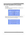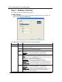
1
VeriTrax AS-215
AC-215's
PC management software
Software Users Guide
August 07
Version 2.05.03
Copyright and Version Number
Information in this document, including URL and other Internet Web site references, is subject to
change without notice. Unless otherwise noted, the example companies, organizations, products,
people and events depicted herein are fictitious and no association with any real company,
organization, product, person or event is intended or should be inferred.
© Copyright 2005 Rosslare. All rights reserved.
Rosslare, the Rosslare logo, and the Rosslare products referred to herein are either the trademarks
or registered to the trademarks of Rosslare, All other trademarks are the property of their respective
owners.
Software License Agreement.
ROSSLARE IS WILLING TO LICENSE THE ENCLOSED SOFTWARE ONLY ON THE
CONDITION THAT YOU ACCEPT ALL OF THE TERMS CONTAINED IN THIS LICENSE
AGREEMENT. This is a legal agreement between you (either the individual or the end-user or an
entity) and Rosslare. By opening this software package, you are agreeing to be bound by the terms
and conditions of this Agreement. If you do not agree to the terms of this Agreement, promptly
return the software package and other items that are part of this product in their original package
with your payment receipt to your point of purchase for a full refund. Grant of License. Rosslare and
its suppliers grant you a nonexclusive license to use one copy of the enclosed software program
(”Software”) on one computer with the Rosslare product you have purchased. No other rights are
granted. The software is in use if it is loaded on the computer’s permanent or temporary memory.
For backup purposes only you may make one copy of the Software. You must include on the
backup copy all copyright and other notices included on the Software as supplied by Rosslare.
Installation on a Network server for the sole purpose of your internal distribution of the Software is
permitted only if you have purchased an individual software package for each networked computer
to which the software is distributed. Restrictions. Rosslare and its suppliers retain ownership of the
Software. You may not decompile, disassemble, reverse engineer, or modify the Software in any
way. You may not transmit the software over a network (except as expressly permitted above), by
telephone, or electrically using any means. You may not transfer the Software except upon a
permanent transfer of the enclosed Rosslare product provided that all software updates are
included in the transfer, you do not retain a copy of the Software, and the transferee agrees to be
bound by the terms and conditions of this license. Upon any violation of any of the provisions of this
Agreement, rights to use the Software shall automatically terminate and the Software must be
returned to Rosslare or all copies of the Software destroyed. Limited Product Warranty. Rosslare
warrants that any hardware products accompanying this documentation shall be free from
significant defects in material and workmanship for a period of one year from the date of purchase.
Rosslare also warrants that the Software accompanying this documentation will perform
substantially in accordance with the documentation for a period of 90 days from purchase.
Rosslare’s hardware and software warranty is nontransferable and is limited to the original
purchaser. Product Remedies. Rosslare’s entire liability and the licensees exclusive remedy for any
breech of warranty, shall be, at Rosslare’s sole option, either a) return the price paid or b) repair or
replacement of hardware or software, provided that the hardware is returned to the point of
purchase, with a copy of the sales receipt. Any replacement hardware and software will be
warranted for the remainder of the original warrantee period or 30 days for the hardware and 30
days for the software, whichever is longer. The remedies are void if failure of the software or
hardware has resulted from abuse, accident or misapplication.
AS-215 PC management software
Page i
Limitation of Liability
THE WARRANTIES SET FORTH IN THIS AGREEMENT REPLACE ALL OTHER WARRANTIES.
ROSSLARE EXPRESSLY DISCLAIMS ALL OTHER WARRANTIES, INCLUDING BUT NOT
LIMITED TO, THE IMPLIED WARRANTIES OF MERCHANTABILITY AND FITNESS FOR A
PARTICULAR PURPOSE AND NON-INFRINGEMENT OF THIRD PARTY RIGHTS WITH
RESPECT TO THE DOCUMENTATION, SOFTWARE, AND HARDWARE. NO ROSSLARE
DEALER, AGENT, OR EMPLOYEE IS AUTHORIZED TO MAKE ANY MODIFICATION,
EXTENSION, OR ADDITION TO THIS WARRANTY. IN NO EVENT WILL ROSSLARE OR IT’S
SUPPLIERS BE LIABLE FOR ANY COSTS OF PROCUREMENT OF SUBSTITUTE PRODUCTS
OR SERVICES, LOST PROFITS, LOSS OF INFORMATION OR DATA, OR ANY OTHER SPECIAL
DIRECT OR INDIRECT, CONSEQUENTIAL, OR INCIDENTAL DAMAGES ARISING IN ANYWAY
OUT OF THE SALE, OF, USE OF, OR INABILITY TO USE ANY ROSSLARE PRODUCT OR
SERVICE, EVEN IF ROSSLARE HAS BEEN ADVISED OF THE POSSIBILITY OF SUCH
DAMAGES. IN NO CASE SHALL ROSSLARE’S LIABILITY EXCEED THE ACTUAL MONEY PAID
FOR THE PRODUCTS AT ISSUE. Because some jurisdictions do not allow the implementation of
limited warranties or liability for incidental, consequential, special, or indirect damages, the above
limitation may not always apply. The above limitations will not apply in case of personal injury where
and to the extent that applicable law requires such liability.
U.S. Government Restricted Rights
The software is provided to the U.S. Government only with restricted rights and limited rights of use,
duplication or disclosure by the U.S. Government is subject to restrictions set forth in 48 C.F.R
2.101 (Oct 1995) consisting of “Commercial Computer Software” and “Commercial Computer
Software Documentation” as such terms are used in 48 C.F.R. 12.212 (September 1995), and in
FAR Sections 52-227-14 and 52-227-19 or DFARS Section 52.227-7013 (C) (ii), or their
successors, as applicable. Consistent with 48. C.F.R. 12.212 and 48 C.F.R. 227.7202-1 through
227.7204-1 (June 1995), or any successor regulations, this software is provided to the terms and
conditions herein. Contractor/ Manufacturer Rosslare Enterprises Ltd. 12 Wang Tai Road, Hong
Kong
Page ii
AS-215 PC management software
Table of Contents
Introduction ..................................................................................... 6
About this manual ............................................................................................................6
System Attributes.............................................................................................................7
Installation........................................................................................ 8
Requirements ...................................................................................................................8
Installation Instructions....................................................................................................8
Accessing the System................................................................... 10
The Veritrax AS-215 Interface....................................................... 11
Menu Bar .......................................................................................................................11
Toolbar...........................................................................................................................16
Tree View ......................................................................................................................17
Events............................................................................................................................... 17
Network ............................................................................................................................ 17
Time zone ......................................................................................................................... 18
Access Groups .................................................................................................................. 18
Access Areas..................................................................................................................... 18
Anti Pass-Back zone ......................................................................................................... 18
Cameras............................................................................................................................ 18
Cards ................................................................................................................................ 19
Users................................................................................................................................. 19
Holidays............................................................................................................................ 19
Operators .......................................................................................................................... 19
Reports ............................................................................................................................. 19
Main Window ................................................................................................................... 19
Principal Operational Procedures................................................ 20
Workflow .......................................................................................................................20
Step 1 - Defining a Network ..........................................................................................21
Panels ............................................................................................................................... 22
Step 2 - Defining Time zone..........................................................................................43
Step 3 - Defining Access Groups...................................................................................44
Step 4 - Creating Cards ..................................................................................................45
Step 5 - Creating Departments\Users.............................................................................49
Step 6 - Defining Access areas ......................................................................................54
Step 7 - Defining Anti Pass-Back zones ........................................................................55
Step 8 - Defining Cameras.............................................................................................56
Step 9 - Defining Status maps........................................................................................58
AS-215 PC management software
Page iii
Table of Contents
Manual Operation......................................................................... 61
Open / Close door ..........................................................................................................61
Network .........................................................................................................................62
Set time ..........................................................................................................................63
Find panels .....................................................................................................................64
Manual operations – Panel.............................................................................................64
Update firmware ............................................................................................................65
Reader mode ..................................................................................................................65
Open Output...................................................................................................................66
Report ............................................................................................. 67
Creating reports..............................................................................................................68
Creating a New Immediate Report:.................................................................................... 68
Creating a New Archive Report:........................................................................................ 69
Creating Attendance Report: ............................................................................................. 71
Creating Access report: ..................................................................................................... 75
Technical Support ......................................................................... 78
Page iv
AS-215 PC management software
Fel! Formatmallen är inte definierad.
Introduction
VeriTrax AS-215 software is user friendly and intuitive. Its graphic interface is
used to define settings, which are downloaded to the AC-215 Access Control
Unit (ACU) and event logs which are uploaded to the PC to generate reports.
The VeriTrax AS-215 software can be installed as a Server or as a Client.
The Server format as to be installed in the PC that is actually connects to the
AC-215 Access Control Unit and holds the system’s database. Server format
operators can run everything on the VeriTrax AS-215 software.
The Client format can be installed on another PC that connects to a VeriTrax
AS-215 Server through the same computers network. Client format operators
are limited in operating few things on the VeriTrax AS-215 software. For
example they cannot deal with the system’s database, cannot change the
network'
s parameters and cannot download new firmware to the ACU.
The system’s database can be set to backup and can import/export previous
configurations.
The software enables features to be added as and when they are needed.
The modular software enables the user interface to be as powerful and
strong as required and yet remains simple to use. The software can be set for
automatic backup on a periodic basis.
About this manual
This manual guides to use the VeriTrax AS-215 software and discusses the
basic actions required for working in the application.
The VeriTrax AS-215 manual is intended for anybody installing and or
commissioning the VeriTrax AS-215 access control system.
This manual is a short guide to using the VeriTrax AS-215 software. It discusses
the basic actions required for working in the application.
System Attributes
•
•
•
•
•
•
•
•
Up to 255 Access Control Units
Up to 255 networks (with one controller per network)
Up to 32 ACU in every network (64 doors in every network)
Up to 5000 users with rights (Up to 25000 users recorded)
64 holidays (copied from MS Outlook – option)
32 time zones
128 access groups
128 anti pass-back zones
AS-215 PC management software
Page 5
Fel! Formatmallen är inte definierad.
Installation
Requirements
•
•
•
•
Operating system: Windows 98/ME/NT/2000/XP
Processor: Pentium 450MHZ Min, RAM memory: 64 MB Min
Optional LAN card for TCP/IP networking
Recommended: Network or local printer for printing function
Installation Instructions
These instructions are for first time installation. However if you already have
the program installed and wish to modify/repair or remove it, follow numbers
1 to 3 only.
To install the VeriTrax AS-215 software
1. Insert the VeriTrax AS-215 CD into your computer’s CD drive.
2. Open My Computer. Double click the CD drive and then click the VeriTrax
AS-215.exe. The VeriTrax AS-215 Install Shield runs and the Welcome
window opens.
3. If you already have the program installed on your computer select one of
the following options (if not continue to number 4):
o Modify, to open the Select Components window. Select either
Program Files and/or ServerDB. Click Next to open the Maintenance
Complete window and then click Next to end the Modify Process.
o Repair, to run the Setup Status. The Installation Complete window
opens, click Yes to restart the program or No not to. Click Finish to
complete the repair process.
o Remove, to remove the program and its files from your computer.
Click Next. A message box opens select Yes to remove the program
and No not to. Click Finish to complete the remove process.
4. Click Next. If this is a first time installation in the Choose Destination
Location window either click Next or, click the Browse button to select a
different location. The Select Application Type window opens.
5. This step has the following two options:
o Select Server if this is a first time installation or if a network is not used.
A server holds the database and connects to the hardware.
o Select Client (if server software is already installed on your network)
and then select the location of the database on the Server PC.
Click Next to open the Select Program folder.
6. Either accept the application’s default or, scroll down and select a
different location. Click Next to run the setup.
7. After completing setup, if prompt, either click Yes to restart your computer
or No not to.
8. Click Finish to end the installation process.
Page 6
AS-215 PC management software
Fel! Formatmallen är inte definierad.
Accessing the System
The VeriTrax AS-215 system is case-sensitive. The default operators are
administrator, engineer and security. Their properties can be modified in the
program.
To access the VeriTrax AS-215 system
1. Double click the VeriTrax AS-215 icon to open the Login dialog box.
2. The Server name field is filled by default and cannot be changed.
In "Operator Name" select administrator and in the Password type admin
3. Click OK to access the application.
AS-215 PC management software
Page 7
Fel! Formatmallen är inte definierad.
The VeriTrax AS-215 Interface
The VeriTrax AS-215 interface has the following panes:
• Menu Bar
• Toolbar
• Tree View
• Main Window
Menu Bar
Menu Submenu Option
Description
File
Logon
Login dialog box opens. A different operator can be chooses from the operator name
menu. The relevant password has to be typed in the password field.
Logoff
Closes the current operator'
s account and minimizes the program to the taskbar.
Exit
Click to Exit the application
Periodic Backup
Select the Backup folder and behavior for automatic Backup operation.
Backup folder – shows the current location of the backup files. Click on the Browse…
button to change the destination folder.
Canceling Database Password – check this option to allow you to view the backed up
database without the need for a password.
Perform backup every - Type or scroll to define the amount of day/s between back
ups (0 indicates no periodic backup).
Perform backup at - Type or to define the time for the automatic backup
Backup now
Select the Backup folder for an immediate Backup.
Canceling Database Password – check this option to allow you to view the backed up
database without the need for a password.
Export configuration
Select this option to copy (Backup) the current configuration to a selected folder using
the Browse button.
Canceling Database Password – check this option to allow you to view the backed up
database without the need for a password.
Tools
Database
Page 8
AS-215 PC management software
Fel! Formatmallen är inte definierad.
Options
Export configuration and Events
Select this option to copy (Backup) the current configuration and all events to a folder
selected using the Browse button.
Canceling Database Password – check this option to allow you to view the backed up
database without the need for a password.
Import configuration
Select this option to replace the current database configuration with the database
folder selected using the Browse button.
Import configuration and Events Select this option to replace the current database configuration and all events with
the database folder selected using the Browse button.
Erase configuration and events Select this option to erase the current database configuration and all events
Import earlier database versions Select this option to replace the current database configuration and all events with a
previous AS-215 database version folder, selected using Browse. (migration can only
be from AS-215 versions 0.5 to 1.2.0)
Limit panel Events period
You can choose to keep events for a certain amount of days while older events are
erased from the system. Type or to define the number of days to reserve events from
the last # Days
Erase panel Events
You can select to keep events beyond a certain date. Select the desired cutoff date
using the date selection box, the system will erase any events from an older date.
General
Default settings:
Auto startup - If this checkbox is marked the AS-215 application will start upon windows
startup.
Language - Select the language for the AS-215 Software interface.
Holidays - If Microsoft Outlook is installed on the computer and this checkbox is
selected, the holiday list from Microsoft Outlook can be imported to the VeriTrax by
clicking on the Outlook tab and selecting the requested holidays to add.
If Microsoft Outlook is not installed on the computer clicking the "Use default holidays"
will insert a fixed holiday'
s database based on the country selected from a country list.
Hasp key - Share Database with VeriTime checkbox – mark this checkbox to activate
the Hasp key control.
Highlight - This option gives the ability to show the difference between users, unknown
keys and alarms by highlighting them in different colors.
Transmit Transactions - This option gives the ability to send data (characters) to the
selected COM Port. This data can be send to a serial input of a video camera (e.g. name of a person who'
s entering his code to the reader and been viewed by this
camera).
AS-215 PC management software
Page 9
Fel! Formatmallen är inte definierad.
Alarm Handler
Enable pop up alarm window.
Enable pop up camera window (by alarm and by access).
s
Alarm Priority- This option enables you to define alarm priority, alarm color and sets if it'
enable or not.
Customize alarm description
Alarm Message - Entering a message will cause it to show when the alarm occurs.
User Fields
This option adds items to the User Fields at the User properties dialog box. The items
can be viewed as a text field, list and checkbox.
User Pop-Up
Allows the user details to pop up in a separate window based on certain selectable
events.
Access Granted – shows the user pop up upon access granted event.
Access Denied – shows the user pop up upon access denied event.
Access Recorded – shows the user pop up upon an event recording of a user with no
access rights who is still set in the database.
The pop up window can be closed manually or automatically after a set amount of
minutes based on your selection.
Report Title
This option opens the Report Title dialog box where the company name appearing on
the system’s report can be defined
Import
Data
Help
Page 10
This option allows for importing of data from external programs into the VeriTrax.
Data Type – Select the file type. Currently only .xls extension files are available
Location – Shows the location of the selected file, click the Browse… to locate the file.
Started from – define the cells within the file to import using the following options:
Row – the first row of applicable data.
User Number started from – starts the numbering using the designated number.
Import departments? - If you select Yes the department column will be activated. If
not select the desired department from the department selection box .
Excel file columns – Check the desired importing details based on the columns used in
the excel file.
About
Click to read information about the VeriTrax AS-215 system version
AS-215 PC management software
Fel! Formatmallen är inte definierad.
Toolbar
The Toolbar is dynamic and changes according to the actions performed in
the system.
Icon
Description
Open door manually. This icon appears throughout the program
Print the list in the main window. This icon appears throughout the
program
Add a new item. This icon appears throughout the program
Edit the selected item. This icon appears throughout the program.
Delete the selected item. This icon appears throughout the program
Delete all
New single/double door
Set time
Update firmware
Readers mode
Open output
Download to panel
Find user
Refresh the events show
Pause the new events appearance
Events view sorted:
Online events by last hour, last day, last week, periodical events(days) or
all events
Immediate reports access events by last hour or periodical events (hours).
Show User properties
Alarm properties and handle.
Modem status
Network Panels
Produce Report
Full screen map
Minimize map
AS-215 PC management software
Page 11
Fel! Formatmallen är inte definierad.
Tree View
Events
Events are real-time occurrences in the system, which can be recorded using
the following objects:
• Panels – Records all events when the door is used.
• Access - Registers the access permission of the person entering the
premises.
• Alarm events - Issued when unusual activity occurs.
• Status map - Represents multiple graphical screens of site floor plans, with
animated icons for doors and alarm points in site.
• System - Events related to server/administrator actions.
Panels, Access Alarm and System events can be displayed with the
following time period screening:
o Last hour
o Last day
o Last week
o Periodical
o All events
Network
The Network module is used to create the connection between the Access
Control Units (ACU) and the PC.
There are three types of media connections:
• Serial
• TCP/IP
• Modem
The panel module, saved in the network, defines user panels. A panel can
be either a single or double door ACU. The selected panel’s address
corresponds to the definitions in the ACU’s dipswitch. A panel can be active
or inactive.
Time zone
The Time zone module defines a specific time that numerous functions can
be performed. Up to eight entrances can be defined per day. There are two
default options:
• Always – 24 hours a day, every day of the week and holiday
• Never – at no time on any day of the week and holiday
Access Groups
This module defines user access to a zone at a set time.
There are two default options:
• Master – can always access all readers, every day of the week
• Unauthorized – cannot access any reader ever but recorded by PC.
Page 12
AS-215 PC management software
Fel! Formatmallen är inte definierad.
Access Areas
This module defines configuration of large sites. Global Area is default area.
Anti Pass-Back zone
This module defines whether user access to a particular access zone should
be permitted or not.
Cameras
This module defines IP network address cameras. It is used to view the
cameras from within AS-215.
Cards
This module displays the card’s details and their assignment to users. There
are two methods for defining new cards:
• Typing the card number into the system
• Passing cards through a card reader that is defined as a reader desktop
After new cards have been processed they are automatically added to the
system.
Users
Each user must be a member of a department and attached to an access
group. Users must have a code, which can be a card, PIN number or both.
In addition a picture of the user can be added to the user properties.
There is an option to increase the user field information for future applications.
Holidays
This module defines the holiday’s date. It is used to set the time zone’s
performance on days that are defined as holidays.
Operators
These are personnel who have different access rights to screens and control
the software.
Reports
This module is used to generate many types of reports for different periods of
time.
Main Window
This pane is dynamic and changes according to the activity performed in it.
AS-215 PC management software
Page 13
Fel! Formatmallen är inte definierad.
Principal Operational Procedures
Workflow
The five-step workflow shown and explained below is a suggested workflow
to configuring the application.
Step 1: Define a network, new panel and doors
Step 2: Define time zones
Step 3: Define access groups
Step 4: Define cards
Step 5: Define Departments\Users
Besides the basic workflow it also recommended to define holidays, and
operators as well as to complete these additional steps: Access areas, Anti
Pass-Back zones, cameras and status maps & reports.
Step 6: Define access areas
Step 7: Define Anti Pass-Back zones
Step 8: Define Cameras
Step 9: Create status Maps
Page 14
AS-215 PC management software
Fel! Formatmallen är inte definierad.
Step 1 - Defining a Network
This step connects the hardware to the PC.
To add a network:
1. In the Tree pane right-click on Networks and click the '
New'button to
open a new Network dialog box.
This dialog box is dynamic and has the following fields:
Field
Sub-field Description
Description
Network name
Network type
This selection must match the dipswitch definitions.
There are four options:
Inactive
If this option is selected the network is inactive and only the
Description and this field are available
Serial
This option is the default. It opens the Serial Network fields:
COM Port – where up to eight ports can be defined
Speed – which can be 9600, 19200, 38400 or 57600
TCP/IP
This option opens the TCP/IP network fields:
Type – choose between Remote (WAN) and Local (LAN). If LAN
was selected press Configuration, if WAN was selected set the IP
address, Port number and serial speed.
IP Address – of the Host LAN Module (view only).
Port Number – of the Host LAN Module (view only).
Speed – set the serial baud rate to 9600, 19200, 38400 or 57600
Configuration – Defines and transfers the network and serial
parameters to the Host LAN Module using Rosslare’s MD-N32.
Modem
This option opens the following fields:
COM Port – where up to eight ports can be defined
Speed – which can be 9600, 19200, 38400 or 57600
Configuration – Defines the phone Number (where the ACU is
located), password, dialing schedule and initialization
conditions to the Host Modem.
AS-215 PC management software
Page 15
Fel! Formatmallen är inte definierad.
Panels
The panel is the actual box attached to the premises door. A panel can be
configured as a single or double door controller.
After a panel and door/s have been added to a network they appear in the
Tree view under the relevant network in order of hierarchy. The view structure
is the number of the panel and the number of its network – shown in brackets.
To add a single/double door controller
1. In the Tree view right click on the relevant Network and select New Panel.
2. Select either Single or Double Door Controller.
o Single Door opens the Single Door Controller – Panel Properties dialog
box.
o Double Door opens the Double Door Controller – Panel Properties dialog
box.
Page 16
AS-215 PC management software
Fel! Formatmallen är inte definierad.
Door Controller - General Tab
This dialog box has the following fields:
Field
General
Sub-field Description
Panel
This is defined in the system. By default the address can only be
address changed once. The dipswitches at the panel have to match
the panel’s address
Enable
Check to activate the panel in the system
panel
checkbox
Inputs
Hardware configurations already defined in the system. This
field is view only.
Inputs of Single and Double Door Controller have different
purpose (inputs or supervised inputs).
Outputs Hardware configurations already defined in the system. This
field is view only.
Outputs of Single and Double Door Controller have different
purpose.
Test button
Click to test the communication with the ACU
Door Controller - Options Tab
This dialog box has the following fields:
Field
Door Anti
Pass-Back
Sub-field
Description
This field is used to ensure that the same card cannot be
used by multiple users in a given period of time
Automatic Anti This field is used to state the Anti Pass-Back time zone
Pass-Back
Hard
denies access and sends alarm to PC
Soft
grants access but sends an alarm to the PC
AS-215 PC management software
Page 17
Fel! Formatmallen är inte definierad.
Reader 1 /
Reader 2
Events filter Select button.
Activates the Anti Pass-Back rules on the checked
readers
This button is for enable to define which events are stored
in panel and reported to PC, see the figure below.
3. Complete the fields in the dialog box and click OK. The panel’s definitions
table opens in the main window and the new panel is added under the
network in the Tree pane.
To add a single/double door controller properties:
1. In the Tree pane Network module double click on the relevant network.
The panel, doors, readers, inputs and outputs are displayed.
2. Double click on the door.
The Single Door Controller dialog box opens.
The Door Controller dialog box for single and double doors is basically the
same. Double door has interlock option between both doors. Therefore the
differences between the two will appear as a note in the relevant location.
Page 18
AS-215 PC management software
Fel! Formatmallen är inte definierad.
Door Property Tab
This dialog box has the following fields:
Field
Door lock
Output 1
Timers
Sub-field
Description
Auto relock
Description
Type in the relevant description for the door
This field has the following options indicating when the
door automatically locks:
None: Lock strike opens for programmed period of time
On door close: Lock strike stops when the door is closed
On door open: Lock strike stops when the door is opened
First person
delay for
unlock
Indicating that automatic unlocked starts after first user
access. This is only available after this checkbox is
checked
Automatic
Select the relevant time zone
unlock
Interlock with At Double Door Controller: Indicating that the door can
Door 1 / Door 2 be opened only if the second door is closed
Door open time This field defines the amount of time that the door is
opened after valid access
Extended door This option is for users that have cards with special access
open time
permission. For example for delivering goods.
Timer- Siren
This field defines that a siren type alarm is sounded.
True for Readers Tamper and Single Door Tamper
3. Double click on the reader. The reader dialog box opens.
AS-215 PC management software
Page 19
Fel! Formatmallen är inte definierad.
Reader - General Tab
Reader General Tab has the following fields:
Field Sub-field
Description
Details Description
Type in the relevant description for the Reader
Operation Mode Select the type of access:
Inactive
Card only – only cards are granted access
PIN only – only PIN codes are granted access
Card or PIN - cards or PIN codes are granted access
Desktop – used to read cards to the PC
Direction In/Out Check the relevant option
Activation
Door (Output 1): When checked indicates that the reader can
open the door lock with a valid code. (For example, do not
open a door in guard tour application)
Auxiliary (Output 2, Single door only): When checked
indicates that the reader can open the Auxiliary output with a
valid code. This option is unavailable in the Double Door
Controller dialog box.
Secure time
This option is for Card + PIN (Secured feature that both card
zone
and PIN are required) and defines the times when access is
permitted
Type Reader Type
This dropdown list has the following options:
None
Wiegand 32 bits data reversed
Clock and data
Wiegand 34 bits
Wiegand 26 bits
Wiegand 40 bits
Wiegand 37 bits
Wiegand 40 bits PCSC
HID Corporate 1000
Wiegand 64 bits
Wiegand 32 bits
Check site code If selected the ACU will provide access (or not) only by the
only
card’s site code
Page 20
AS-215 PC management software
Fel! Formatmallen är inte definierad.
Keypad type
This dropdown list has the following options:
None
Wiegand 6 bit (Rosslare)
Wiegand 6 bit burst
Wiegand 8 bit burst
Reader - Options Tab
Reader Options Tab has the following fields:
Field
Sub-field
Timed Anti
pass-back
Automatic Anti
Pass-Back
Hard
Soft
Time
Site codes Site code
Sounder
Description
This field is used to ensure that the same card is not used by
multiple users in a given period of time.
This field is used to state the anti pass-back time zone
denies access and sends alarm to PC
grants access but sends an alarm to the PC
This field is used to define the anti pass-back time
This feature is valid only if the Check site code only checkbox
is checked.
It has the following sub-fields:
Add from list – select from the list of the known site codes
Add manually – adds a manually typed site code
Remove – removes a site code from list
Chime by
Access granted
This field defines that a chime type alarm is sounded by
Access granted event.
Bell by keypad
button
This field defines that a bell type alarm is sounded by the
keypad button.
4. Double click on Door REX input. The input dialog box opens.
AS-215 PC management software
Page 21
Fel! Formatmallen är inte definierad.
Door REX Dialog Box
supervised panel
unsupervised panel
This Dialog box has the following fields:
Field
Description
Input Function
Description
Type in the relevant description for the input
REX Door only
Type (active for Select between:
supervised
Normally Open
only)
Normally open (with) 1 resistor
Normally open (with) 2 resistors
5. Double click on Door monitor input. The input dialog box opens.
Page 22
AS-215 PC management software
Fel! Formatmallen är inte definierad.
Door Monitor Input - General Tab
supervised panel
unsupervised panel
When you first connect the software and activate a panel, VeriTrax checks if
the connection is supervised or not. If the connection is supervised, you see
two buttons, Test and OK. It is recommended to use the OK button which
performs a test and moves on to the next stage.
If the detected connection is not supervised, under Type, you can select
between supervised and normal.
Door Monitor Input General Tab has the following fields:
Field
Details
Description
Type in the relevant description for the input
AS-215 PC management software
Page 23
Fel! Formatmallen är inte definierad.
Function(Input 1
and Input 2 for
Door Monitor only
Double Door only)
Type (active for
Select between:
supervised only) Normally Close
Normally close (with) 1 resistor
Normally close (with) 2 resistors
Door Monitor Input - Alarms Tab
When you first connect the software and activate a panel, VeriTrax checks if
the connection is supervised or not. If the connection is supervised, you see
two buttons, Test and OK. It is recommended to use the OK button which
performs a test and moves on to the next stage.
If the detected connection is not supervised, under Type, you can select
between supervised and normal.
Door Monitor Input Alarms Tab has the following fields:
Field
Timers
Chime
Sub-field
Door held
open alert
Door held
open
Door forced
open
Siren
Description
Time for door to be opened before an alarm alert condition starts
Time for door to be opened before an alarm condition starts
Time for door to be forced open before an alarm condition starts
This field defines that a siren type alarm is sounded in the following
options: Door held open and Door forced open
This field defines that a chime type alarm is sounded in the following
Chime(Input Input 1A opened (Door monitor)
1A opened)
Note: In the Double Door Controller Chime Door 2 tab this field has the
following option: Input 2A opened
Door held
open alert
Page 24
This field defines that a chime type alarm is sounded in the following
Door held open alert.
AS-215 PC management software
Fel! Formatmallen är inte definierad.
6. Double click on Panel Tamper input (Single door only). The input dialog
box opens.
Panel Tamper Input - General Tab
supervised panel
unsupervised panel
When you first connect the software and activate a panel, VeriTrax checks if
the connection is supervised or not. If the connection is supervised, you see
two buttons, Test and OK. It is recommended to use the OK button which
performs a test and moves on to the next stage.
If the detected connection is not supervised, under Type, you can select
between supervised and normal.
Panel Tamper Input General Tab has the following fields:
AS-215 PC management software
Page 25
Fel! Formatmallen är inte definierad.
Field
Description
Description
Type in the relevant description for the input
Input Function
Type (active for
supervised only)
Tamper only
Select between:
Normally Close
Normally close (with) 1 resistor
Normally close (with) 2 resistors
7. Double click on Panel General Purpose input (Single door only). The input
dialog box opens.
Panel Input - General Tab
supervised panel
unsupervised panel
Page 26
AS-215 PC management software
Fel! Formatmallen är inte definierad.
Panel Input General Tab has the following fields:
Field
Description
Input Function
Type (active for
supervised only)
Description
Type in the relevant description for the input
General Purpose only
Select between:
Normally Open
Normally open (with) 1 resistor
Normally open (with) 2 resistors
Bell (Input 2A
Closed)
This field defines that a chime type alarm is sounded in the
following Input 2A closed
8. Double click on Alarm Output. The output dialog box opens.
Alarm Output - General Tab
This tab is used to define how this output will be activated.
Alarm Output General Tab has the following fields:
Field
Description
Operation mode
Description
Type in the relevant description for the input
This field has the following options:
None: Output is inactive
Door held open alert: When selected, the output is activated in the
door held open alert condition
Door held open: When selected, the output is activate in the
door held open condition
Door forced open: When selected, the output is activate in the door
forced condition
Door Tamper & trouble: When selected, the output is activate during
reader tamper and trouble conditions
All door alarms: When selected, the output is activate in any of the
above alarm conditions
Automatic operation: When selected the output is activated by the
fields of the Automatic operation below
AS-215 PC management software
Page 27
Fel! Formatmallen är inte definierad.
Automatic
Operation
This field defines the activity time zone, if operation mode is in the
automatic operation
Timer
Set the duration of the output activation for all but automatic operation.
9. Double click on Auxiliary Output (Single door only). The output dialog box
opens.
Auxiliary Output - General Tab
Auxiliary Output General Tab has the following fields:
Field
Sub-field Description
Auxiliary Operation This field has the following options:
(Output 2) Mode
None: Output is inactive
Users with right: When selected, only authorized users can activate
the output (see user information field)
Access granted: When selected, every access granted activates the
output
Access denied: When selected, every access denied activates the
output
Keypad bell button: When selected, pressing the bell key in the
keypad reader activates the output
Automatic operation: When selected, the output is activated
automatically according the time zone schedule
Output
This field has the following options:
Mode
Toggle – toggles the output in every operation
Time – activates the output for a specified period time
Automatic This field defines the activity time zone, if operation mode is in
Operation automatic operation
10. Double click General Output (Single door). The output dialog box opens.
Page 28
AS-215 PC management software
Fel! Formatmallen är inte definierad.
General Output - General Tab
When you first connect the software and activate a panel, VeriTrax checks if
the connection is supervised or not. If the connection is supervised, you see
two buttons, Test and OK. It is recommended to use the OK button which
performs a test and moves on to the next stage.
If the detected connection is not supervised, under Type, you can select
between supervised and normal.
General Output General Tab has the following fields:
Field
Sub-field Description
General Operation This field has the following options:
(Output 2) Mode
None: Output is inactive
Input 2A: When selected, the output is activated by input 2A.
Automatic Operation: When selected, the output activates
automatically according to the time zone schedule below
Output
This field has the following options:
Mode
Follow Input2A – output follows Input2A activation
Toggle – toggles the output in every operation
Time – activates the output for a specified period of time
Automatic This field defines the activity time zone, if operation mode is in
Operation automatic operation
AS-215 PC management software
Page 29
Fel! Formatmallen är inte definierad.
Step 2 - Defining Time zone
This module defines intervals of time during different days of week and
holidays.
Time zones define various automatic operations and time that a user can
enter/exit the premises.
There are two default options:
o Always – always active
o Never – never active
To define Time zone Properties:
Double click on a time zone option. The Time zone Properties dialog box
opens.
To define new access permission, click the timetable on the relevant date at
time. A tick appears in the relevant position.
Click Clear All to empty the timetable
o Up to 8 entrances/exits can be defined per time zone
o Hours must be in sequential order
o The End time must be larger than the Start time
o Time zones can be removed/edited by right clicking on the time zone
in the list and selecting either edit/delete
Page 30
AS-215 PC management software
Fel! Formatmallen är inte definierad.
Step 3 - Defining Access Groups
The Access Group is a combination of readers and time zones. Each user
must belong to an access group that has specific access permissions. In
addition each reader has specific time zones.
There are two default access groups:
o Master – can always enter a premises
o Unauthorized – can never enter a premises, but always recorded
o To add a new access group:
To define Access groups Properties:
Right click on the Access Group module and select New. The Access Group
dialog box opens.
To modify Access Group, in the Time zone column click the relevant time
zone. Select appropriate Time zone from the dropdown list. The Time zone
definition is modified.
o Access Groups (except for Master and Unauthorized) can be
removed/edited by right clicking on the access group in the list and
selecting either edit/delete.
Step 4 - Creating Cards
When this option is clicked a list of all cards and their status opens in the main
window.
AS-215 PC management software
Page 31
Fel! Formatmallen är inte definierad.
o
o
Cards can be removed by clicking on a specific card in the list and
pressing the "delete" icon above.
All the cards can be removed by pressing the "delete all" icon above.
To create a new card:
There are three options to create new cards:
1. Right click on Cards and then click New. The Add Cards dialog box
opens.
Page 32
AS-215 PC management software
Fel! Formatmallen är inte definierad.
This Dialog box has the following fields:
Field
Reader
type
Sub-field
Clock & data
Wiegand
26 Bits
Wiegand
37 Bits
HID Corporate
1000`
Wiegand 32
bits
Wiegand 32
bits data
reversed
Wiegand 34
bits
Wiegand 40
bits
Wiegand 40
bits PCSC
Wiegand 64
bits
Sequential Cards
cards
quantity
Start from
New user
Description
Cards to be read by a reader with Clock & Data outputs format
Cards to be read by a reader with Wiegand 26 bits outputs format
Cards to be read by a reader with Wiegand 37 bits outputs format
Cards to be read by a reader with HID Corporate 1000 outputs
format
Cards to be read by a reader with Wiegand 32 (MSB first) bits
outputs format
Cards to be read by a reader with Wiegand 32 (LSB first) bits
outputs format
Cards to be read by a reader with Wiegand 34 bits outputs format
Cards to be read by a reader with Wiegand 40 bits outputs format
Cards to be read by a reader with Wiegand 40 bits PCSC outputs
format
Cards to be read by a reader with Wiegand 64 bits outputs format
This field holds the number of cards to add
This field indicates the initial code number from which the card’s
sequence starts
Site code
Valid for Wiegand 26 bits, HID corporate 1000 and Wiegand 40 bits
PCSC only.
This field indicates the number of the site code (0-255). This number
is not changed during the sequential cards addition
New user
check box
Check this option to create a new user when adding cards based
on the card quantity.
User number Enter the first user number for the group of users you are adding.
started from
2. Left click on one of the panels. Press button Reader Mode on Toolbar.
A Dialog box is opened used to change the AC-215 reader'
s modes.
AS-215 PC management software
Page 33
Fel! Formatmallen är inte definierad.
Select one of the options ‘Change operation mode…’ and select
operation mode ‘Desktop’. Press Apply. To imprint cards, swipe them over
one of selected readers. Select option ‘Default’ and press ’Apply’.
3. Double click on one the readers. The reader dialog box opens. Select
operation mode ‘Desktop’. Press OK. To imprint cards, swipe them over
selected reader. Return reader operation mode.
Step 5 - Creating Departments\Users
It is recommended that users be added after the department to which it is
attached has been defined. However, a user can always be added to the
General department. The General department is the application’s default
and cannot be removed. After a user has been defined it is added to the
Department'
s users list, which can be viewed in the main menu.
This step is divided into two stages:
o Creating departments
o Adding a user to a department
To add a department:
1. Right click on the Departments\Users module and click New Department
to open the Department dialog box.
Page 34
AS-215 PC management software
Fel! Formatmallen är inte definierad.
2. In the Description field type in the department name and then click OK.
The department is added to the Departments List in the main view.
To add a user to a department:
Right click the relevant department and click New User to open the User
Properties dialog box.
This dialog box has the following tabs:
o General
o Codes
o Details
o User fields
AS-215 PC management software
Page 35
Fel! Formatmallen är inte definierad.
Add User to Department – General Tab
Add User to Department General Tab has the following fields:
Field
Photo
Sub-field
Description
Add/
To add a photo to a user click the Add button to open the
Remove Button Windows Open dialog box and locate the file holding the
relevant photo
Click to remove the user’s photo
Personal First name
Type in the user’s first name
Details
Middle name
Type in the user’s middle name
Last name
User number
Department
Access group
Valid date From
Until
Rights
Type in the user’s surname
Sequential number fixed by the application. A user’s number
can only be modified when first defined
Click the dropdown list and select the relevant department
Click the dropdown list and select the relevant access group
Scroll and find the relevant date
Check this option if the user can enter/exit the premises up to
and including a specific date, and then scroll to define the date
Select color
This feature has to be enabled from: Tools Options Highlight
Use highlight user events Selected user.
Click to select a color making this user unique from others.
Location
Press the button to quickly receive report about locations for that
particular user.
Activate
auxiliary output
Extended door
open time
If selected, the user will have the authority to activate the
auxiliary output
When this user opens a door it will be activate for a prolonged
period of time. The length of time is defined in the Door
properties dialog box
Anti Pass-Back If selected, the user will not be affected by the Anti pass-back
Immunity
feature
Page 36
AS-215 PC management software
Fel! Formatmallen är inte definierad.
Add User to Department – Codes tab
Add User to Department Codes Tab has the following fields:
Field
Cards
Sub-field
Code/Status
Add from list
Add manually
Remove
PIN Code Number of
digits
Description
This field lists the cards codes and their status .The status can be
change from Active to Inactive
Click and select a card number from the cards list that already
purchased by the system. Click Add or Cancel to finalize.
Click to manually create new cards .Click Add or Cancel to
finalize.
Click the Remove button to delete selected card numbers.
Click the dropdown list and select the number of digits in the PIN
code
Code
This number is the PIN code to be used in a ‘PIN only’ and ‘Card
or Pin’ reader modes or in secure mode (Card + PIN)
Auto PIN
Click to generate a random number that has the specified
number of digits.
AS-215 PC management software
Page 37
Fel! Formatmallen är inte definierad.
Add User to Department – Details Tab
This tab has the following fields:
Field
Telephone
Mobile
Description
Fill this field with relevant information
Fill this field with relevant information
Fax
Email
Address
Home telephone
Fill this field with relevant information
Car registration
Position
Employment date
Fill this field with relevant information
Notes
Details Button
Fill this field with relevant information
Fill this field with relevant information
Fill this field with relevant information
Fill this field with relevant information
Fill this field with relevant information
Fill this field with relevant information
Allows you to upload a file related to the user
Add User to Department – User Fields Tab
This tab is an expansion to the regular user details. Define in: Tools Options
User Fields and can be implemented as text or list with a scroll bar or an
information check box.
• Forward & Back arrows
o Use the arrows to quickly navigate between Users and navigate with
user number.
Page 38
AS-215 PC management software
Fel! Formatmallen är inte definierad.
•
New Users button
o Use the button to quickly add a new user without closing the existing
user and open a new one again.
Step 6 - Defining Access areas
By setting ’Access areas’, configuration and maintenance of large sites can
be greatly simplified. It also allows Anti pass-back zone and reports to be
generated on defined access areas.
Global Area is default external Access area.
To add a new Access area:
Right click on one of define Access areas module and select New. The
Access area dialog box opens.
AS-215 PC management software
Page 39
Fel! Formatmallen är inte definierad.
Step 7 - Defining Anti Pass-Back zones
Anti Pass-Back zone feature is used when in and out access is controlled.
Because AS- 215 knows whether a user is inside a particular area or out, it can
be intelligent about whether access should be permitted or not. A user must
first exit an area before being allowed to re-enter. This feature can only work
in on-line systems where AS-215 is opened all time.
To add a new Anti Pass-Back zone:
Right click on one of define Anti pass-back zones module and select New.
The Anti pass-back zone dialog box opens.
This dialog box has the following fields:
Field
Description
Access areas
Automatic Anti Pass-Back
Hard
Description
Type in the relevant description for the anti pass-back zone
This field defines the protected access area.
This field is used to state the anti pass-back time zone
Denies access and sends alarm to PC
Soft
Grants access but sends an alarm to the PC
Step 8 - Defining Cameras
To add a new camera:
Right click on the Cameras module and click New Camera to open the
Camera dialog box.
Page 40
AS-215 PC management software
Fel! Formatmallen är inte definierad.
Enter a network IP address.
To define events for camera popup:
Double click on Reader icon open reader alarm and access events dialog
box.
Double click on Door icon open Door alarm dialog box
AS-215 PC management software
Page 41
Fel! Formatmallen är inte definierad.
Step 9 - Defining Status maps
Right click on the Maps module and click New Status Map to open the Status
map screen.
Right click on the Doors, Readers, Cameras and other Status Maps to add
them to current Status map.
Right click on Doors, Readers, Cameras and other Status Maps icons to define
properties.
Use Alarms menu to open Door or Reader dialog box (see Camera
definition). Check alarm events to show on Status Map.
Return to Online mode with click on Refresh button.
Page 42
AS-215 PC management software
Fel! Formatmallen är inte definierad.
If selected alarm event occur, alarm icons will shown:
Double click on the icon open alarm handle dialog box.
Alarm Message – see Menu Options, Alarm handler.
AS-215 PC management software
Page 43
Fel! Formatmallen är inte definierad.
Manual Operation
There are several manual operations that can be done after VeriTrax AS-215
is installed and run.
Open / Close door
Open momentary – All checked doors are opened and closed automatically
after the "open door timer" elapsed.
Open permanently – All checked doors are opened permanently and stay at
this status until a manually Close operation.
Close – All checked doors are closed and return to automatic operation.
This option is always accessible and is displayed on the toolbar, first left.
Page 44
AS-215 PC management software
Fel! Formatmallen är inte definierad.
Network
The network status is displayed on the right side of the screen for any network
selection. An information on panels address connectivity and versions.
There are few manual operations that can be done after VeriTrax AS-215 is
installed and running on panel selection.
Set time
Set the time for all doors that had been checked. The date is taken from the
PC clock. This window also can be used to see the current date and time of
every panel in the network.
AS-215 PC management software
Page 45
Fel! Formatmallen är inte definierad.
Find panels
This feature is very useful for rapid installations. By clicking "Test", the VeriTrax
AS-215 searches for all the connected panels in the network and present the
panel type. Then checks the panels and activates them by clicking apply.
VeriTrax AS-215 will download all the setup information to the entered panels.
Manual operations – Panel
The network panel is displayed on the right side of the screen on. An
information on panel output status and connectivity. There are few manual
operations that can be done after VeriTrax AS-215 is installed and running on
panel selection.
Page 46
AS-215 PC management software
Fel! Formatmallen är inte definierad.
Update firmware
The VeriTrax AS-215 allows updating of the AC-215 firmware. At the end of the
process, the panel configuration will automatically download to the panel.
Reader mode
VeriTrax AS-215 allows changing AC-215 reader'
s modes. First select the
changed mode, check the readers and then click "Apply".
Open Output
VeriTrax AS-215 allows open / close outputs or siren for testing or permanently.
First select the operation mode, check the outputs and then click "Apply".
AS-215 PC management software
Page 47
Fel! Formatmallen är inte definierad.
Report
The Reports folder is divided into two folders "Immediate" and "Archive".
•
Immediate
the immediate folder contain two default reports Who Has Been In Today
and Last Known Position. It shows an immediate list on the screen'
s left
side.
o Who'
s been in today shows when and where the employee was granted access for the
first time today.
o Last known position shows when and where the employee was granted access for the
last time today.
The additional two reports are roll call reports, based on readers or areas.
Time filters are defined using the toolbar button.
•
Archive
All the other reports are located in the archive folder.
Page 48
AS-215 PC management software
Fel! Formatmallen är inte definierad.
Creating reports
Creating a New Immediate Report:
Right click on "Immediate" in the tree view and click New to open the reports
wizard.
This Dialog box has the following fields:
Field
Which report
do you want to
produce?
Sub-field Description
Roll-Call Roll-Call Readers report presents last access granted and access
Readers recorded users, sorted by department and date.
Roll-Call Roll-Call Areas report presents users located inside selected
Areas
access area, sorted by department and date.
Creating a New Archive Report:
1. Right click Archive in the tree view and click New to open the reports
wizard.
AS-215 PC management software
Page 49
Fel! Formatmallen är inte definierad.
This dialog box has the following fields:
Field
Sub-field
Which report
Panels events report
do you want to
produce?
Description
Roll-Call Readers report presents last access
granted and access recorded users, sorted
by department and date.
System AS-215 events report Roll-Call Areas report presents users located
inside selected access area, sorted by
department and date.
Interactive report
Combination of PC and Access Control. You
can ask employees details and rights.
Which report
Attendance report
Attendance report presents working hours of
do you want to (Panels events report type) the selected users, sorted by date. You can
produce?
choose the report type: only presence hours,
from first in to last out, or only once a day
movements.
Panels report
Panels report presents all the events of the
(Panels events report type) panels, sorted by date.
Access report
Access report presents all the access events
(Panels events report type) from the readers, sorted by events and date.
Areas report
Areas report presents users located inside
(Panels events report type) selected access area, sorted by department
and date.
Readers report
Readers report presents users access, sorted
(Panels events report type) by department and date.
Access report
Access report presents all the access events
(Panels events report type) from the readers, sorted by events and date.
System report
System report presents all the operations
(System AS-215 events
done at the VeriTrax AS-215 system, sorted by
report type)
date.
Operators report
Operators report presents all the operations
(System AS-215 events
done by the operators, sorted by events and
report type)
date.
Alarms report
Alarms report presents all the system alarms
(System AS-215 events
handle, sorted by operator and date
report type)
User details
User details report presents users name, cards
(Interactive report type)
and PIN code, Access group and other
details.
Users access rights
Users’ access rights report presents users
(Interactive report type)
access by readers and Time zones.
Not responding users
Not responding users report presents users
(Interactive report type)
without access events in selected interval of
time.
Page 50
AS-215 PC management software
Fel! Formatmallen är inte definierad.
Creating Attendance Report:
2. In Step 1-Report type screen, Choose Attendance report and click Next.
3. In Step 2-Users, add the users or departments needed for the report and
click Next.
4. In Step 3-Readers, add the readers needed for the report and click Next.
AS-215 PC management software
Page 51
Fel! Formatmallen är inte definierad.
5. In Step 4-Options, select the computed dates needed for the report and
click Next.
This dialog box has the following fields:
Field
Save as
Sub-field
File name
Save as type
Location
Compute
options
Page 52
Report type
Description
Report description in Tree view, automatically
saved file name.
The report saved in HTML or .Dat formats after
manual or automatic report production.
File saving location after manual producing
report.
You can choose the report type: only
presence hours, from first in to last out, or only
once a day movements.
Style
You can choose the report Style: detailed or
summary.
Days selector
You can select which days will be viewed ,or
not, at the report
Auto arrival
Completes the arrival report –if missing.
Auto exit
Over night
Start working
End working
Completes the exit report –if missing.
Reports the exact working hours at night shift.
Beginning work time
Ending work time
AS-215 PC management software
Fel! Formatmallen är inte definierad.
6. In the last step, specify report production details and then click Finish.
This dialog box has the following fields:
Field
Manual
Automatic
Sub-field
In the last X days
Description
Check this option and select the days
needed to be reported
In the last X months
Check this option and select the months
needed to be reported
Between X and Y
Check this option and select the date
limitation needed to be reported
Each X days
Check this option and select period for
generate automatic report.
In each X day of week
Check this option and select day of week for
generate automatic report.
In each X day of month
Check this option and select day of month
for generate automatic report.
Time
Start from
Time of automatic report producing.
AS-215 PC management software
Initial starting point
Page 53
Fel! Formatmallen är inte definierad.
Creating Access report:
1. In Step 1-Report type, Choose Access report and click Next.
2. In Step 2-Users, add the users or departments needed for the report and
click Next.
3. In Step 3 - Access events, add the events needed for the report and click
Next.
Page 54
AS-215 PC management software
Fel! Formatmallen är inte definierad.
4. In Step 4-Options, select the dates and file saving format needed for the
report and click Next.
This dialog box has the following fields:
Field
Save as
Sub-field
File name
Save as type
Location
Description
Report description in Tree view,
automatically saved file name.
The report saved in the format HTML after
manual or automatic report production.
File saving location after manual producing
report.
5. In the last step specify the report production details and then click Finish
AS-215 PC management software
Page 55
Fel! Formatmallen är inte definierad.
Technical Support
Asia Pacific, Middle East, Africa
Rosslare Security Products Headquarters
905-912 Wing Fat Industrial Bldg,
12 Wang Tai Road,
Kowloon Bay Hong Kong
Tel:
+852 2795-5630
Fax:
+852 2795-1508
E-mail: [email protected]
United States and Canada
1600 Hart Court, Suite 103
Southlake, TX, USA 76092
Toll Free: +1-866-632-1101
Local: +1-817-305-0006
Fax:
+1-817-305-0069
E-mail: [email protected]
Europe
Global Technical Support & Training Center
HaMelecha 22
Rosh HaAyin, Israel 48091
Tel:
+972 3 938-6838
Fax:
+972 3 938-6830
E-mail: [email protected]
South America
Pringles 868, 1640 Martinez
Buenos Aires
Argentina
Tel:
+54 11 4798-0095
Fax:
+54 11 4798-2228
E-mail: [email protected]
Web Site: www.rosslaresecurity.com
Page 56
AS-215 PC management software
0706-0960188+00