1
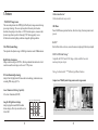
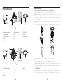
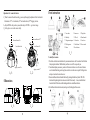
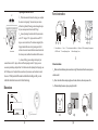
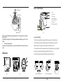
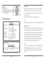
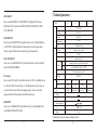
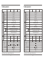
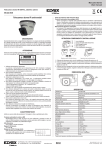
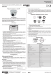
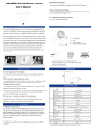
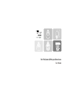
Ultra Wide Dynamic (IR Waterproof) Dome Camera
User's Manual
1 Overview
2 Notes
SA series Ultra WDR cameras are new, CCTV cameras which adopt Pixim's
innovative “SEAWOLF” image sensor chip based on Digital Pixel System ®
1. Use the Appropriate Power Supply
The input power will be DC12V or DC12V/AC24V dual-power. Be sure to connect
technology. The resolution is up to 690TVL-E and the industry-leading wide dynamic
it to the appropriate power. Wrong connection may cause malfunction and damage to
range is up to 120dB. This WDR ensures brilliant image quality under any lighting
the video camera.
environment. The image and color quality is also excellent in low illumination
2. Do not attempt to disassemble the camera.
environments. This camera series is a ultra wide dynamic range camera in the real sense
To prevent electric shock, do not remove screws or covers. There are no user ser
using digital sampling which can't be paralleled by average wide dynamic range
-viceable parts inside. Ask a qualified service person for servicing.
cameras using older generation CCD imagers. The application of 3D digital noise
3. Handle the camera with care.
reduction technology ensures higher S/N, which efficiently reduces the digital storage
Do not abuse the camera. Avoid striking, shaking, etc. The camera could be dam
and transmission data saving system cost. Fashionable and professional exterior design
-aged by improper handling or storage.
and special all-in-one all directional bracket, makes round-the-clock surveillance easy
4. Do note use strong or abrasive detergents when cleaning the camera body
and convenient.
Use a dry cloth to clean the camera when dirty. In case the dirt is hard to remove
. Use a mild detergent and wipe gently.
5. Do not put the camera in a place with interference
When this camera is installed near the equipment like wireless communication
device which emits strong electromagnetic field, some irregularity such as noise
on monitor screen may happen.
A
B
C
D
E
F
G
H
3.Features
All directional bracket*
All directional bracket, easy control.
SEAWOLF Image Sensor
This camera adopts innovative DPS(Digital Pixel System) image sensor and image
processing technology. The sensor picks up details from each pixel based on
hundreds of samples per video frame. vs CCD's limited exposures, to ensure wider
dynamic range than is possible with analog CCD. The image quality is even
brilliant under extreme lighting conditions.changeable lighting condition.
Ultra Wide Dynamic Range
The captured wide dynamic range is 102dB typical and can reach 120dB maximum.
OSD Menu
Powerful OSD menu operation function, allows for setting of various paramters and
pre-sets.
IR-CUT*
Built-in filter switch-over device, ensures the cameras work properly both in day and night.
DC12V/AC24V Dual Voltage*
High Effective Resolution
Image resolution as high as 690TVL-E, offering enhanced horizontal and vertical
resolution useable in existing as well as new CCTV systems.
Compatible for DC12V and AC24V voltage. which can shift to the correct
mode as per the power input.
Notice
3D Noise Eliminating Technology
Adopts Pixim fully digitalized 3D noise reduction technology to minimize noise,
extending DVR storage by 30%+.
the function with
* ,different type different function.
Comparison of Wide Dynamic Range camera and average camera
Lower Illumination Working Capability
0.1Lux low illumination (IR OFF)
Long-effective IR Light Source Design
IR Sensnsitivity
Long-life IR Light Source Design
Adopts high performance IR LED and heat
balance design, effectively extends the service
life of LED.
Average camera with BLC off
Other brands
1yr
2yr
3yr
4yr
Service Life
Average camera with BLC on
Ultra Wide Dynamic Range camera
Camera installation
1 loose the 3 glass cover screw by screwdriver ,take the glass cover out.
2 loose the Installed setscrews , to separate the subpanel from camera body.
3 Drill 3 holes in the position needed in accordance with the installation hole on the subpanel ,
push the Expansion Bolt inside then tighten the screws,make the installation hole aim at the three
screws and fix it.
4 Choose the way the wire out, if out from the ceiling, then need a hole on it, if from the side of
the camera, then just need to loose the Stages of a screw the lid , get the wire out from it.
4.Parts instruction
Focus
A
Zoom
B
5.Stages of a screw the lid
9.LED ALARM
6. OSD
10. Subpanel
2. Glass cover screw hole
7.IR LED
11. Install screws hole
3. Base
8.LENS
1. Dome Enclosure: to protect
camera lens and body.
4. Wire out hole
Focus
C
1. Dome Enclosure: to protect
Zoom
D
4. OSD
7. Subpanel
camera lens and body.
5.IR LED
8. Install screws hole
2. Glass cover screw hole
6.LENS
3. Base
1 loose the 3 glass cover screw by screwdriver ,take the glass cover out.
2 loose the Installed setscrews , to separate the subpanel from camera body.
3 Drill 3 holes in the position needed in accordance with the installation hole on the subpanel ,
push the Expansion Bolt inside then tighten the screws,make the installation hole aim at the three
screws and fix it.
4 Choose the way the wire out, if out from the ceiling, then need a hole on it, if from the side of
the camera, then just need to loose the Stages of a screw the lid , get the wire out from it.
Adjust ment for camera direction
1 When the camera fixed on the ceiling , you can ajust the angle by adjustment of the 3 axis bracket.
Maximmum 355 vertical rotation, 35 horizontal rotation,355 dipping rotation.
2 Adjust ZOOM to the position you need, then adjust FOCUS to get clearer image.
3 Fix the glass cover on the camera body.
Parts instruction
1. Cover dome
4. Main body
Horizontal Rotation 355
Horizontal Rotation 355
Vertical Rotation35
Vertical Rotation35
dipping rotation355
B
dipping rotation355
C
D
C
D
5.Dimensions
A
B
3. Wing locker
5. IR Leds.
6. Mount bracket
7. Ceiling mount opener 8. Zoom lever
10.Tilt fixing screw
11.Switch board
13.Locker
9. Focus lever
12.Groove mark
14.Lock releaser
E
A
2. Inner cover
F
To install your camera
1.Press the Locker button on the bottom of your camera and remove the Cover dome from the Main
body using the other hand. The Main body and Inner cover will be exposed to you.
2.To install and adjust your camera, you have to first remove the Inner cover. To remove the Inner
cover from the Main body, push a long thin screwdriver into the narrow spot of the Wing locker
and press it outward to remove the cover.
3.Remove the Mount bracket from the Main body by rotating the Main body in the UNLOCK
direction while pushing the Lock releaser out ward. If it is not easily done, rotate the Mount
bracket in the LOCK direction while holding small holes on the Mount bracket.
4.Fix the Mount bracket to the location (ceiling or wall) with supplied three screws.
Adjusting the camera direction
355
35
Lens rotation
1
When the camera is fixed on the ceiling, you can adjust
the camera viewing angle. You can rotate your camera
leftward or rightward (Panning), and can change the slope
of your camera upward or down ward (Tilting).
2 In case of panning, the rotation limit of yourcamera is
set to 355 degree (100 degree clockwise and 255
degree counterclockwise). The rotation is stopped by the
Stopper inside of the camera. For panning control, first
unfasten two screws located on the bottom and rotate in the
direction you want, and then fasten them to fix the camera.
Parts instruction
1. Dome Enclosure 2. Lens 3. Three-dimensional Bracket 4. Bracket 5. IR Transmitting Components
6. DIP Switch 7. Zoom Adjusting Lever 8. Focus Adjusting Lever
G
3 In case of tilting, you can change the slope of your
camera from zero to 90 degree. However if the slope angle is under 17 degree, you can
encounter a partial image hide problem. To fix the location after adjusting the tilting angle, use
the Tilt fixing screws. To adjust the focus and zoom of your camera, use the Zoom lever and
Before Installation
Focus lever. When you install the camera on the inclined ceiling or wall, you can
about to install.
rotate the camera lens to see a correct direction image.
2 Do not have the cable in an improper place or broken, otherwise, these may cause a fire.
1 Make sure the installation position can bear a weight 5 times heavier than the camera you are
3 When installing the camera, please properly install it.
Dimensions
E
F
Horizontal Rotation 355
Parts instruction
1
2
3
4
5
6
7
Vertical Rotation45
dipping rotation355
When your camera is fixed to the wall, you can adjust camera s three-dime nsion al brac ket to the
angle you need.
1.Horizontally rotating angle 355 (Bracket panel and main board installing panel can both be
rotated.)
2.
Vertically rotating angle 45
Adjust the lens focal length to the position you need and adjust the lens focus again to get a clear
picture.
Dimensions
G
H
Lens
Zoom Screw
Focus Screw
Camera Mainbody
Angle Fixxing Screw
Camera base
Base Installation Hole
H
Camera Installation
1.Set the camera installing location and fix the camera onto wall with screws.
2.Take the Allen wrench in tool bag and unscrew the angle fixing screw and
adjust the camera to required vertical angle and then fix the screw.
3.Take the Allen wrench in tool bag and unscrew the angle fixing screw and adjust
the camera to required horizontal angle and then fix the screw.
4.The focal length can be adjusted through zoom and focus botton
camera horizontal angle adjustment
camera vertical angle adjustment
Zoom
focus
OSD Menu Setup
Menu button for choice
Move Up And Down By Up And Down Button
Move Horizontally Or Modify Parameter By
Left And Right Button
WDR Control:
Press Enter to show the menu, move the cursor to WDR Control, set MEDIUM,
NORMAL, LOW, HIGH by left and right button; choose the setting for WDR in
accordance with the lighting condition, set High in strong lighting contrast to realize
higher quality image.
WDR ZONE SELECT:WD NROMAL/SAFE AREA/ATM/LOW 1/3.
6. OSD Menu Operation
BLC:
CAMERA SETUP
MEDIUM (LOW/NORMAL/MEDIUM/HIGH)
(OFF/ON)
OFF
(ATW/AWB)
ATW
NORMAL (LOW/NORMAL/HIGH)
(MANUAL/DC)
DC
(OFF/CRR/CRR2)
OFF
AUTO
(OFF/AUTO/GPIO)
ENGLISH (ENGLISH/CHINESE)
DEFAULT(CANCEL)
WDR CONTROL
BLC
WHITE BALANCE
AGC
LENS SELECT
FLUORESCENT
D/N CONTROL
LANGAGE SELECT
SAVE
move to BLC by Up and Down button, set BLC by Left and Right button: On and Off.
WHITE BALANCE:
Move to White Balance by Up and Down button, set White balance by Left and Right
button: AWB: Auto White Balance; ATW: Auto Tracking White Balance. The color's
temperature are different in different lighting condition, The color's temperature
changes in different lighting condition, so the white color in video image changes if
the lighting condition changes. AWB means cameras can compensate color
temperature automatically. In some special environment, in order to keep the same
color temperature , ATW setting can keep a fixed color temperature
WDR ZONE SELECT:
AGC:
NORMAL METER PRESETS
PRESETS
PRE
WD NROMAL
SAVE
WD NROMAL/SAFE AREA/ATM/LOW1/3
CANCEL
*Specialists press "Left, Right, Left, Right, Down" button enter superior menu.
Move cursor to AGC by Up and Down button, set AGC by Left and Right Button as :
NORMAL, LOW and HIGH. Setting AGC is better for cameras to work in wider
lighting range, if the illumination is low, can set AGC high to rise the sensitivity of
cameras.
7.Technical parameter:
LENS SELECT:
Move cursor to LENS SELECT, set LENS SELECT by Right and Left button as :
Sensor
Resolution
690HTVL-E
0.1Lux
>50dB AGC OFF
medium, normal, low, high
BLC
ON, OFF
AGC
normal, low, high
Mode
Tracking White Balance, Auto White Balance(ATW)
White Balance
Automatic
Auto White Balance 2200~10000 K
D/N
D/N Control:
OFF, External Control, Auto; ON
SYNC Mode
as: OFF; Auto;GPIO: External Control; On. The illumination is very low at night, so
Power
Move cursor to D/N Control by Up and Down button, set D/N by Left and Right button
INTERNAL
Voltage
DC12V
DC12V/AC24V
DC12V
DC12V/AC24V
current
<200mA
<250mA
<200mA
<250mA
4-9mm
4-9mm Auto iris
2.8-12mm
2.8-12mm Auto iris
we need to rise the sensitivity and improveimaging quality, then we can get better
Lens
image quality. Set D/N in accordance with different actual need.
IR Range
IR CUT
SAVE&EXIT:
Working Temperature
Move cursor to SAVE&EXIT by Up and Down button, set by Left and Right button
as : SAVE&EXIT;DEFAULT,CANCEL.
148(
Size
)*112( H )
850g
Weight
*Specification is subject to change without prior notice
15
A-4
DPS Sensor
PAL/NTSC
WDR control
Menu Control
button as : ENGLISH;CHINESE.
1/3
Video Format
S/N Ratio
as: OFF, CRR2: Color Rolling Restrain. Cameras output color roll ing image under
fluorescent lamp, CRR can restrain colorrolling, keep the image stable.
Move cursor to LANGAGE SELECT by Up and Down button, set by Left and Right
A-3
Mini illumination
Move cursor to FLUORESCENT by Up and Down button, set by Left and Right button
LANGAGE SELECT:
A-2
Sensor
AUTO IRIS LENS.
FLUORESCENT:
A-1
Model
MANUAL,DC:DC Automatically. MANUAL FOR MANUAL IRIS LENS, DC for
16
Technical parameter:
Technical parameter:
B-1
Model
B-2
Sensor
B-3
1/3
690HTVL-E
0Lux;(IR-ON )
Mini illumination
ON, OFF
AGC
normal, low, high
Mode
Tracking White Balance, Auto White Balance(ATW)
White Balance
Automatic
Auto White Balance 2200~10000 K
D/N
SYNC Mode
DC12V/AC24V
DC12V
DC12V/AC24V
current
<400mA
<450mA
<400mA
<450mA
4-9mm Auto iris
2.8-12mm
IR Range
IR CUT
2.8-12mm Auto iris
BLC
ON, OFF
AGC
normal, low, high
Mode
Tracking White Balance, Auto White Balance(ATW)
White Balance
Automatic
Auto White Balance 2200~10000 K
OFF, External Control, Auto; ON
Auto Switchover
Working Temperature
INTERNAL
Voltage
DC12V
DC12V/AC24V
DC12V
current
<200mA
<250mA
<200mA
<250mA
4-9mm
4-9mm Auto iris
2.8-12mm
2.8-12mm Auto iris
Lens
IR Range
20 M
Auto Switchover
Power
Power
DC12V
4-9mm
>50dB AGC OFF
medium, normal, low, high
SYNC Mode
INTERNAL
Voltage
Lens
0Lux;(IR-ON )
D/N
OFF, External Control, Auto; ON
DPS Sensor
690HTVL-E
Resolution
WDR control
Menu Control
Menu Control
BLC
IR CUT
Working Temperature
148(
Size
)*112( H )
850g
Weight
*Specification is subject to change without prior notice
17
C-4
PAL/NTSC
S/N Ratio
medium, normal, low, high
C-3
1/3
Video Format
Mini illumination
>50dB AGC OFF
S/N Ratio
WDR control
C-2
Sensor
DPS Sensor
PAL/NTSC
Resolution
C-1
Model
Sensor
Sensor
Video Format
B-4
136(
Size
)*112( H )
700g
Weight
*Specification is subject to change without prior notice
18
DC12V/AC24V
Technical parameter:
Technical parameter:
D-1
Model
D-2
Sensor
D-3
1/3
DPS Sensor
PAL/NTSC
690HTVL-E
Resolution
Menu Control
Menu Control
BLC
ON, OFF
AGC
normal, low, high
Mode
Tracking White Balance, Auto White Balance(ATW)
White Balance
Automatic
INTERNAL
DC12V
<450mA
<400mA
4-9mm
<400mA
4-9mm Auto iris
IR Range
IR CUT
DC12V
DC12V/AC24V
0.1Lux
2.8-12mm
DC12V/AC24V
<450mA
2.8-12mm Auto iris
OFF
ON,OFF
BLC
AGC
White
Balance
normal, low, high
Mode
Tracking White Balance, Auto White Balance(ATW)
Automatic
Auto White Balance
OFF, External Control, Auto; ON
INTERNAL
DC12V
Voltage
Current
Lens
<400mA
<200mA
4-9mm Fix iris
2.8-12mm Fix iris
4-9mm Fix iris
Auto Switchover
IR CUT
Working Temperature
Working Temperature
136(
Size
)*112( H )
700g
Weight
*Specification is subject to change without prior notice
19
2.8-12mm Fix iris
20M
IR Range
20 M
Auto Switchover
0Lux;(IR-ON )
medium, normal, low, high
SYNC Mode
Power
Power
Lens
690HTVL-E
D/N
OFF, External Control, Auto; ON
SYNC Mode
current
PAL/NTSC
Resolution
Auto White Balance 2200~10000 K
D/N
Voltage
Video Format
WDR control
medium, normal, low, high
WDR control
F-2
DPS Sensor
S/N Ratio
>50dB AGC OFF
S/N Ratio
F-1
1/3
Mini illumination
0Lux;(IR-ON )
Mini illumination
E-2
Sensor
Sensor
Sensor
Video Format
E-1
Model
D-4
128(
Size
)*91( H )
550g
Weight
*Specification is subject to change without prior notice
20
Technical parameter:
Technical parameter:
G-1
Model
G-2
Sensor
G-3
1/3
690HTVL-E
0Lux;(IR-ON )
Mini illumination
OFF
S/N Ratio
AGC
Mode
Tracking White Balance, Auto White Balance(ATW)
Auto White Balance
D/N
OFF, External Control, Auto; ON
SYNC Mode
INTERNAL
DC12V/AC24V
DC12V
DC12V/AC24V
Current
<400mA
<450mA
<400mA
<450mA
4-9mm Auto iris
20M
IR Range
IR CUT
2.8-12mm Fix iris 2.8-12mm Auto iris
690HTVL-E
Mini illumination
0Lux;IR-ON
medium, normal, low, high
ON,OFF
Working Temperature
AGC
White
Balance
normal, low, high
Mode
Tracking White Balance, Auto White Balance(ATW)
Automatic
Auto White Balance
D/N
OFF, External Control, Auto; ON
INTERNAL
Voltage
DC12V
DC12V/AC24V
DC12V
DC12V/AC24V
Current
<350mA
<400mA
<350mA
<400mA
4-9mmFix iris
4-9mmAuto iris
Lens
IR Range
Auto Switchover
Auto Switchover
Power
Power
DC12V
4-9mm Fix iris
PAL/NTSC
Resolution
SYNC Mode
Voltage
Lens
IR CUT
2.8-12mmFix iris 2.8-12mmAuto iris
20M
Auto Switchover
Auto Switchover
Working Temperature
185(
Size
)*150( H )
1400g
Weight
*Specification is subject to change without prior notice
21
H-4
DPS Sensor
Video Format
BLC
normal, low, high
Automatic
1/3
WDR control
ON,OFF
Menu Control
Menu Control
BLC
H-3
S/N Ratio
medium, normal, low, high
WDR control
H-2
Sensor
Sensor
Sensor
PAL/NTSC
Resolution
H-1
Model
DPS Sensor
Video Format
White
Balance
G-4
116(
Size
)*93( H )
650g
Weight
*Specification is subject to change without prior notice
22