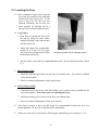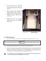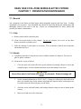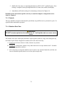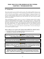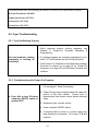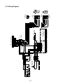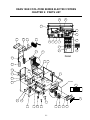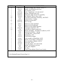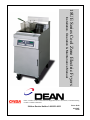
1
18UE Series Cool Zone Electric Fryers
Installation, Operation & Maintenance Manual
Dean, a member of the Commercial Food Equipment Service Association, recommends using
CFESA Certified Technicians.
24-Hour Service Hotline 1-800-551-8633
Price: $6.00
819-5657
06-00
Please read all sections of this manual and retain for future reference.
Installation, maintenance, and repairs should be performed by your Dean
Factory Authorized Service Center.
CAUTION
DO NOT STORE OR USE GASOLINE OR OTHER FLAMMABLE VAPORS AND LIQUIDS IN
THE VICINITY OF THIS OR ANY OTHER COOKING APPLIANCE.
WARNING
IMPROPER INSTALLATION, ADJUSTMENT, ALTERATION, SERVICE, OR
MAINTENANCE CAN CAUSE PROPERTY DAMAGE, INJURY OR DEATH. READ THE
INSTALLATION, OPERATING AND MAINTENANCE INSTRUCTIONS THROUGHLY
BEFORE INSTALLING OR SERVICING THIS EQUIPMENT.
WARNING
SAFE AND SATISFACTORY OPERATION OF YOUR EQUIPMENT DEPENDS ON ITS
PROPER INSTALLATION. INSTALLATION MUST CONFORM TO LOCAL CODES, OR IN
THE ABSENCE OF LOCAL CODES, WITH THE LATEST EDITION OF THE NATIONAL
ELECTRIC CODE, N.F.P.A. 70.
i
18UE Series Cool Zone Electric Fryers
TABLE OF CONTENTS
Page #
1.
INTRODUCTION
1-1
2.
IMPORTANT INFORMATION
2-1
3.
INSTALLATION INSTRUCTIONS
3-1
4.
FRYER OPERATIONS
4-1
5.
COMPUTER/CONTROLLER OPERATION
5-1
6.
FILTER OPERATION
6-1
7.
PREVENTATIVE MAINTENANCE
7-1
8.
TROUBLESHOOTING
8-1
9.
PARTS LIST
9-1
ii
DEAN 18UE COOL ZONE SERIES ELECTRIC FRYERS
CHAPTER 1: INTRODUCTION
1.1 Ordering Parts
Customers may order parts directly from their local Authorized Parts Distributor. For this address
and phone number, contact your Maintenance & Repair Center or call the factory. The factory
address and phone numbers are on the cover of this manual.
To speed up your order, the following information is required:
Model Number
Serial Number
Optional
Equipment
Item Part Number
Type
With/Without
Filter
Quantity Needed
1.2 Service Information
Call the 1-800-551-8633 or (318) 865-1711 Service Hotline number for the location of your nearest
Maintenance & Repair Center. Always give the model and serial numbers of your filter and fryer.
Also, identify which cooking computer or controller is installed on your fryer.
To assist you more efficiently, the following information will be needed:
Model Number
Serial Number
With/Without
Filter
Optional
Equipment
Nature of Problem:
Type
Computer/Controller
Additional information (i.e. cooking environment, time of day, and other pertinent information) may
be helpful in solving your service problem. Communicate with your service technician.
1-1
1.3 After Purchase
In order to improve service, have the following chart filled in by the Dean Authorized Service
Technician who installed this equipment.
Authorized Service
Technician/FASC
Address
Telephone/Fax
Model Number
Serial Number
Gas Type
1.4 Safety Information
Before attempting to operate your unit, read the instructions in this manual thoroughly.
Throughout this manual, you will find notations enclosed in double-bordered boxes similar to the
ones below.
CAUTION boxes contain information about actions or conditions that may cause or result in a
malfunction of your system.
CAUTION
Example of a CAUTION box.
WARNING boxes contain information about actions or conditions that may cause or result in
damage to your system, and which may cause your system to malfunction.
WARNING
Example of a WARNING box.
DANGER boxes contain information about actions or conditions that may cause or result in injury
to personnel, and which may cause damage to your system and/or cause your system to malfunction.
DANGER
Hot cooking oil causes severe burns. Never attempt to move a fryer containing hot
cooking oil or to transfer hot cooking oil from one container to another.
1-2
DEAN 18UE COOL ZONE SERIES ELECTRIC FRYERS
CHAPTER 2: IMPORTANT INFORMATION
2.1 General
The Dean 18UE Electric Cool Zone Fryers are energy-efficient, electrically heated units, certified by
Underwriters Laboratory and manufactured to their basic performance and application
specifications. The 18UE is certified by AFNOR for installation and operation in the European
Community (CE).
All units are shipped completely assembled with accessories packed inside the frypots. All units are
adjusted, tested and inspected at the factory before shipment.
CAUTION
The on-site supervisor is responsible for ensuring that operators are made aware of
the inherent dangers of operating a hot oil fryer/filter system, particularly the aspects
of fryer operation, oil filtration, and draining/cleaning procedures.
DANGER
The fryer MUST be connected only to an electricity source that exactly matches
voltage type and phase listed on the attached rating plate.
2.2 Rating Plate
Information on this plate includes the model and serial numbers, as well as electrical requirements.
When communicating with the factory about a unit or requesting special parts or information, this
data is essential for proper identification.
2.3 Pre-Installation
A. GENERAL: All installation and service on this equipment must be performed by qualified,
certified, licensed, and/or authorized installation or service personnel. A list of Dean
Authorized Service Centers is included with the fryer when shipped from the factory.
If you do not have access to this list, please contact the Frymaster/Dean Technical Service
Department using the following phone numbers, 1-800-551-8633 (US/Canada) or 1-318865-1711 (Worldwide).
NOTE: Failure to use qualified service personnel will void the Dean warranty.
2-1
B. STANDARDS: All electrical cooking appliances must be electrically connected and
grounded in accordance with local codes, or in the absence of local codes, with the latest
editions of:
1. United States of America:
National Electric Code Standards ANSI/NFPA # 70.
American National Standards Institute
1430 Broadway
New York, NY 10018
NFPA Standards #96 and #211.
National Fire Protection Association
470 Atlantic Avenue
Boston, MA 02110
2. Canada: Canadian Electrical Code Part 1, CSA-C22.1.
Canadian Standards Association
178 Rexdale Boulevard
Rexdale, ONT
M9W 1R3
3. European Community (CE): All electrical cooking equipment must be electrically
connected and grounded in accordance with local codes, or in the absence of local
codes, with the latest editions of the appropriate national or European Community (CE)
standards.
C. CLEARANCES: The fryer area must be kept free and clear of all combustibles. This unit is
design-certified for the following installations:
1. Other than household use;
2. Non-combustible floor installation equipped with factory-supplied 15 cm (6 inches)
adjustable legs or optional 15 cm (5-inch wheel) rigid rear casters;
3. Combustible construction with a minimum clearance of 15 cm (6 inches) side and 15 cm
(6 inches) rear, and equipped with factory-supplied 15 cm (6-inch) adjustable legs or 15
cm (5-inch wheel) rigid rear casters.
CAUTION
Local building codes usually prohibit a fryer with its open tank of hot oil from being
installed beside an open flame of any type, whether a broiler or the open burner of a
range.
2-2
2.4 Unpacking the Fryer/Component Systems
Ensure the container is upright. Unpack the fryer carefully and remove all accessories from the
carton. Do not discard or misplace these, as they will be needed.
After unpacking, immediately check the equipment for visible signs of shipping damage. If
such damage has occurred, contact the carrier and file the appropriate freight claims. Do not
contact the factory, as the responsibility of shipping damage is between the carrier and the
dealer or end-user.
If your equipment arrives damaged:
a. File claim for damages immediately – Regardless of extent of damage.
b. Visible loss or damage – Be sure this is noted on the freight bill or express receipt and is
signed by the person making the delivery.
c. Concealed loss or damage – If damage is unnoticed until equipment is unpacked, notify
freight company or carrier immediately, and file a concealed damage claim. This should be
done within fifteen (15) days of date of delivery. Retain the shipping container for
inspection.
NOTE: Dean does not assume responsibility for damage or loss incurred in transit.
If your equipment arrives without casters or legs installed, leave the equipment on the pallet
and do not cut the banding straps until ready to install casters or legs.
WARNING
Dean fryers equipped with legs are for permanent installations. Fryers fitted with
legs must be lifted during movement to avoid damage and possible bodily injury. For
a moveable or portable installation, Dean optional equipment casters must be used.
Questions? Call 1-800-551-8633
WARNING
Do not attach accessories to this fryer unless fryer is secured from tipping.
Personal injury may result.
2-3
DEAN 18UE COOL ZONE SERIES ELECTRIC FRYERS
CHAPTER 3: INSTALLATION INSTRUCTIONS
3.1 Installing the Fryer
A. Initial Installation: If installed with legs, do not push against any unit edges to adjust its
position. Use a pallet or lift jack to lift it slightly and place it where it is to be installed.
B. Relocating the Fryer: If relocating a fryer installed with legs, remove all weight from each
leg before moving.
Note:
If a leg becomes damaged during movement, contact your service agent for immediate
repair/replacement of the damaged leg.
DANGER
This fryer may tip and cause personal injury if not secured correctly in a stationary
position. Drain all oil/shortening from fryer before moving. Hot oil will splash and
cause severe burns upon contact.
3.2 Leg and Caster Installation
A. General
1.
Install legs and rear rigid casters near where the fryer is to be used, as neither are secure
for long transit. Unit cannot be curb mounted and must be equipped with the legs and
rear rigid casters provided.
2.
When positioning the fryer, gently lower the fryer into position to prevent undue strain
to the legs and internal mounting hardware. Use a pallet or lift jack to lift and position
the fryer if possible. Tilting the fryer may damage the legs.
3.
The rigid casters must be installed on the fryer rear channel assembly only.
4.
Proceed to Step 3.3, Leveling, after legs and rear rigid casters are installed to ensure the
fryer is level before using.
B. Leg and Rigid Caster Installation
1. Remove unit from pallet.
2. Carefully raise unit with forklift, pallet jack, or other steady means.
3. Place one lock washer on each hex head screw.
3-1
4. Insert hex head screws with lock washers (1/4-20 threads by 19-mm (¾") long) through
bolt holes of leg mounting plates and mount to the front channel. Mount rigid casters to
the rear channel following the same procedure. A locknut has been attached to the
topside of the base mounting plates at the factory to capture the hex head screw as it is
screwed in.
5. Tighten the bolts to 5.65 joules (50 inch-lbs.) minimum torque.
CAUTION
For caster retrofit, the unit must be at room temperature and drained of shortening
before installing the casters.
WARNING
If optional swivel casters are used, locking casters must be installed on the fryer
front channel. Failure to lock casters prior to operating the fryer will increase the
likelihood of fryer movement, and the potential for injury to the operator.
C. Installing Optional Swivel Casters:
1. Install non-locking casters only at the rear of the unit.
2. Locking casters must be installed at the front of the unit. Locking casters allow the fryer
to be "locked" in position for safe operations.
3. Follow the same instructions for leg installations as given above in steps 3.2, B1-5.
Front View
Rear Side View
Optional CasterRear Only
Optional CasterFront Only
Rear Caster— 5" Rigid
Front Caster— 5" Swivel
w/Brake
1/4-20 x 3/4 Hex Bolt
Front Channel or
Rear Channel
Front Channel
or Rear Channel
Leg Support Assembly
Washer
1/4-20 Hex Head Locknut
Front or Rear Leg with
Mounting Plate
1/4-20 x 3/4 Hex Bolt
Adjust as needed
Leg and Caster (Optional) Mounting Installation
3-2
3.3 Leveling the Fryer
A. Place a carpenter’s spirit level across the
top of the fryer and level the unit both
front-to-back and side-to-side. If the
fryer is not level, the unit may not
function efficiently, the oil may not
drain properly for filtering and in a
line-up it may not match adjacent units.
B. Legs (Only)
1. If the floor is smooth and level, level
the unit by using the caster shims.
Adjust to the high corner and measure
with the spirit level.
2. Adjust leg height with an adjustable
wrench, or a 27-mm (1-1/16”) openend wrench by turning the hex bullet
on the bottom of the leg.
Adjusting leg height with an adjustable wrench
3. The hex bullet is for minor leg height adjustment only. Do not adjust more than 22-mm
(1").
C. Rigid Casters (Only):
1. Install the optional rigid casters on the fryer rear channel only. Legs must be installed
on the front channel.
2. There are no thread adjustments for the rigid casters.
D. Swivel Casters (Only):
1. If optional swivel casters are used, the locking swivel casters must be installed on the
fryer front channel. Lock casters prior to operating the fryer.
2. Install non-locking swivel casters on the fryer rear channel only.
3. There are no thread adjustments for the swivel casters.
E. If the floor is uneven or has a decided slope, it is recommended to place the fryer on a
smooth platform. Do not rely on leg threads for adjustments.
F. If the fryer is moved, re-level the fryer following the instructions given in Steps 3.3, A-C.
3-3
G. ANSI Z83.11a-1997 requires a fryer be restrained to prevent tipping when installed in
order to avoid the splashing of hot liquid. The means of restraint may be the manner
of installation, such as connection to battery of appliances or installing the fryer in an
alcove, or by separate means, such as adequate ties. A bracket has been provided on the
fryer back panel for this purpose.
The install must be reviewed at the time of installation to ensure it meets the intent of
these instructions. The on-site supervisor and/or operator(s) should be made aware
that there is a restraint on the appliance and, if disconnection of the restraint is
necessary, to reconnect this restraint after the appliance has been returned to its
originally installed position.
3.4 Electrical Connections
CAUTION
The fryer MUST be connected to the voltage and phase as specified on the rating
and serial number plate located on the back of the fryer door.
A ground wire MUST be connected to the ground terminal provided near the input
power terminal block.
Plan and implement installation in accordance with local codes. Service connections should be
made at the power input terminal block, located through the back lower portion of the fryer and
through the component box, located under the control wireway. It is recommended that this
connection be made by means of an approved, flexible-metallic or rubber-covered electrical cable
and a quick-disconnect plug. This connection should be made by means of a CE, UL, CUL, or CSA
approved quick-disconnect plug. If rigid or flexible-metal conduit connections are required, they
must be made through the rear portion of the fryer cabinet, to the fryer input terminal block.
CAUTION
Connections must be made by qualified service personnel only.
A. Wiring Diagram: It is attached to the inside of the fryer door. Amperage for each unit
depends on the type of installation and accessories supplied with the unit.
B. Emergency Cutoff System: Be sure that each fryer is connected to a dedicated set of contacts
in an emergency cutoff system.
1.
Do not attempt to connect the contacts in series.
2.
Do not connect more than one fryer to each set of contacts.
3-4
3.
The contacts must be normally closed contacts that open during an emergency.
4.
Do not apply external voltage to the contacts.
3.5 Operating Switches
A.
Fryer/Filter Switches
1.
Fryer Power Switch: Located on the right-hand side of the computer. It transfers the
power from the computer to that individual fryer’s heating element circuits.
2.
Pump Power Switch: Located on the right fryer-cabinet control panel of the fryer
battery. It operates the Super Cascade filter pump motor.
3.
Drain Valve Micro-switch: The
computer will display “HELP” when
the drain valve is opened. The
computer will lockout and prevent
any
cooking
operation
until
“EXIT/COOL FILTER” is pressed.
Microswitch located on red-handled drain-valve
4.
Filter Pump Reset: Located in the
right fryer cabinet. This switch
resets the Super Cascade filter pump
motor.
5.
Manual Filter Override Switch:
Located in the right fryer control
panel of the fryer battery. This
toggle or rocker switch allows the
operator to manually operate the
Super Cascade Filter if a problem
develops with the auto functions.
Filter pump reset switch
3-5
Manual filter override switch
WARNING
If the filter pump safety switch repeatedly trips out, do not continue to reset. A
potential safety hazard exists. Contact an authorized service technician for
troubleshooting.
B. Filter Operation Handles:
1.
Red: Drain Valve Handle. Turn to open. This handle (located in the fryer cabinet)
should be in the closed (Down) position except when filtering.
2.
Yellow: Oil Return Valve. Turn to open. This handle (located in the fryer cabinet)
should be in the closed (Up) position except when filtering.
C. Fryer Controllers: Your 18UE Fryer System comes equipped with a Compu-Fry
Computer, or a Solid State Analog Controller.
1.
Fryer with Compu-Fry Computer
This fryer/filter system is equipped with drain valve safety switches on the two battered
fryers to de-energize the fryer heating elements during the filter process. This is for
additional safety. You should always turn the fryer power switch “OFF” prior to
filtering.
2.
a.
Fryer Power Switch: Located on the right-hand side of the computer. It transfers
the power from the computer to that individual fryer’s heating element circuits.
b.
Pump Power Switch: Located on the filter cabinet control panel of the fryer battery.
It operates the filter pump motor.
c.
Drain Valve Micro-switch: The computer will display “HELP” when the drain
valve is opened. The computer will lockout and prevent any cooking operation
until drain valve is closed.
Fryer with Solid State (Analog) Controller
a.
Power Switch - controls power to the fryer.
b.
Power On Light - indicates when electrical power is on.
c.
Temperature Knob - sets desired frying temperature.
d.
Heat Mode Light - indicates when elements are on (heating).
3-6
e.
Trouble Light - indicates solid state controller system lockout. To reset, turn power
switch OFF for 30 seconds, then ON.
f.
Melt Cycle Switch - controls melt cycle operation.
g.
Melt Cycle Light - indicates fryer is operating in the melt cycle mode.
Additional information on controller/computer features and functions can be found in Chapter 5.
3-7
DEAN 18UE COOL ZONE SERIES ELECTRIC FRYERS
CHAPTER 4: FRYER OPERATIONS
4.1 Initial Start-Up
A. Cleaning: New units are wiped clean with solvents at the factory to remove any visible signs
of dirt, oil, grease, etc. remaining from the manufacturing process, then coated lightly with
oil. Before any food preparation, wash thoroughly with hot, soapy water to remove any film
residue and dust or debris then rinse out and wipe dry. Also wash any accessories shipped
with the unit. Close the drain-valve completely and remove the crumb screen. Make sure
the screws holding the thermostat and high-limit control sensing bulbs into the vessel are
tight.
4.2 Boil-out Procedure
CAUTION
Do not leave fryer unattended. The boil-out solution may foam and overflow if fryer is
left unattended. Press ON/OFF switch to the OFF position to control this condition.
4.2.1 Fryer with Solid State (Analog) Controller
A. Before switching the fryer ON, close the fry vessel drain valve, fill empty fry vessel with a
mixture of cold water and heavy-duty low-sudsing degreaser compound to the oil level line
scribed in the back of the fry vessel. Follow instructions on bottle when mixing.
B. Press fryer ON/OFF switch to the ON position.
C. Set temperature control knob to 200°F (93°C).
D. Allow the solution to simmer for 45 minutes to one hour. Do not permit the water level to
drop below the oil-level line in fry vessel during boil-out operation.
E. Carefully monitor the fryer during this time to prevent solution from boiling over.
F. Turn the fryer ON/OFF switch to the OFF position.
G. Add sufficient cold water to lower temperature to a safe level. Drain out the solution and
clean the fry vessel thoroughly.
H. Refill the fry vessel with clean water. Rinse the fry vessel twice, drain and dry inside of pot
thoroughly to remove all residual water. Repeat this process for each fry vessel in multibattered fryers.
4-1
CAUTION
Water or boil-out solution MUST NOT be allowed to drain into the filter pan or filter
system. Irreversible damage will result if water is allowed into the system.
4.2.2 Fryer with Compu-Fry Computer
A. Before switching the fryer ON, close the fry vessel drain valve, then fill empty fry vessel
with a mixture of cold water and heavy-duty low-sudsing degreaser compound to the oil
level line scribed in the back of the fry vessel. Follow instructions on bottle when mixing.
B. Turn the computer ON by pressing
C. Press the
D. Enter
switch.
.
will appear in the left display.
(1 6 5 3) in that sequence. The right display will read
.
E. The temperature is automatically set at 195°F (91°C). The fryer will maintain this
temperature until the OFF switch is pressed to cancel the boil-out mode.
F. Follow the directions on the cleaning solution container. Simmer the solution.
G. After the recommended boil-out time period (approximately 45 minutes to 1 hour) press the
computer OFF button.
H. Add sufficient cold water to lower temperature to a safe level. Drain out the solution and
clean the fry vessel thoroughly.
I. Refill the fry vessel with clean water. Rinse the fry vessel twice, drain, and wipe down the
fry vessel(s) with a clean towel.
NOTE: Perform this boil-out procedure at least once a month.
J. Fill the fry vessel with oil/shortening as directed below.
CAUTION
All drops of water MUST be removed from fry vessel before filling with cooking oil.
Residual water will cause splattering of hot oil/shortening and increase the potential
for burn injury.
WARNING
Hot shortening can cause severe burns. Avoid contact. Under all circumstances, oil
must be removed from the fryer before attempting to move it to avoid oil spills and
the falls and severe burns that could occur. This fryer may tip and cause personal
injury if not secured in a stationary position. See instruction manual.
4-2
4.2 Final Preparation
A. The 18UE fry vessel shortening capacity is approximately 90 pounds (40.5Kg).
B. Ensure fryer power switches are “OFF”.
C. Remove the basket-support rack.
D. When using liquid shortening or cooking oil, fill the fryer to the “oil level” line scribed into
the back of the fry vessel. If the fry vessel has two oil fill lines, fill to the lower oil fill line.
Reinstall the basket-support rack.
WARNING
NEVER set a complete block of solid shortening on top of heating elements. To do
so will damage the elements and increase the potential for flash-point shortening
temperatures and subsequent fire.
WARNING
NEVER operate fryer without sufficient oil/shortening or water in the fry vessel to
cover the heating elements.
E. When using solid shortening, either melt it first, or cut into small pieces and pack into cool
zone (bottom) of the fry vessel. Be careful to not leave any air spaces in fry vessel or
disturb the sensing bulbs.
1. Compu-Fry Computer: Turn computer ON (this turns the fryer ON also). The computer
will run the fryer through the melt cycle to melt the shortening. The computer display
will show
until the shortening reaches 180°F (82°C). The fryer heating elements
will cycle ON and OFF to more efficiently melt the shortening. When the fryer comes
out of melt cycle, the fryer will go into continuous heat mode until the setpoint
temperature is reached.
2. Triac: The Triac electric fryer with computer operates differently from other electric
fryers. The Triac pulses ON and OFF continuously while it operates. This pulsing saves
energy and makes this model type very efficient. It will operate in a melt cycle mode
until the shortening reaches the setpoint temperature.
3. Solid State (Analog) Controller. When the melt cycle switch is ON, the controller will
melt the shortening by cycling the elements ON for 3 seconds and OFF for 12 seconds
until the shortening reaches 180°F (82°C). At that point, the controller switches to
continuous heat mode until setpoint has been reached.
4-3
F. After shortening reaches the setpoint temperature, let the heating elements cycle at least
four times, then insert a thermometer or pyrometer near the temperature sensing probe
approximately 3 inches (7.5-mm) deep into the shortening. When the heating elements
cycle ON after the fourth time, the thermometer should read within ± 5°F (± 2°C) of the
temperature control knob setting or computer programmed temperature. If not, calibrate the
temperature control knob by loosening the two setscrews and moving the knob to the proper
temperature setpoint. See Chapter 5 for specific instructions to recalibrate the Solid State
(Analog) Controller.
G. When the fry vessel is filled and the shortening melted, replace the basket-support screen
over the heater elements. The fryer is now ready for use.
4.3 Daily Operation
4.3.1 General Use
A. For consistent quality product, convenience and long-term savings, use a high-quality liquid
frying oil/shortening.
B. If using solid shortening, never melt a block of shortening by setting it whole in the fryer
vessel.
C. Although 350°F (177°C) is the recommended temperature for most cooking operations, set
the fryer at the lowest possible temperature which produces a high quality end product while
ensuring maximum life of oil/shortening.
4.3.2 Fryer ON Procedures
A. If fryer is empty, pour enough oil/shortening into the vessel to fill the vessel to the "oil
level” line scribed on the rear wall. If solid shortening is to be used, melt the shortening
following procedures in section 4.2, Final Preparation, page 4-3 of this manual.
B. Solid State Controller: Turn the fryer power switch “ON”; turn the temperature controller
knob to 350°F (177°C). The oil/shortening temperature will stabilize in approximately 30
minutes and be ready for production. See Chapter 5 of this manual for detailed information.
C. Compu-Fry Cooking Computer: Turn the computer “ON” and select a product-cooking
program as described in Chapter 5 of this manual.
4.3.3 Filtering
A. General: Filter the frying oil/shortening at least once daily or more frequently if cooking is
heavy. This assures the longest life possible for the oil/shortening while maintaining a high
quality product. Frequent filtering also minimizes flavors being transferred from one product
batch to another.
4-4
CAUTION
When filtering, never leave the filter unattended. Oil moving through the lines could
JOLT a flexible return hose out of the filter pan, spraying hot oil and causing severe
burns.
B. Solid Shortening: If using solid shortening, clear return lines before turning off the filter
motor by allowing the pump to run for approximately 30-60 seconds after air bubbles appear
in the fry vessel from the oil return line. Failure to do so will allow solid shortening to cool,
solidify and clog the lines.
C. Read Chapter 6 for general information about using the optional Super Cascade Filter
system or the Filter Installation & Operation Manual provided with your Dean
Filtration System for specific operating instructions for your filter unit.
4.3.4 At Closing
When closing at night, filter oil/shortening in all fryers and drain the filter lines. Cover open tanks
of oil and turn the power switch “OFF”.
4.3.5 Periods of Non-usage
When shutting down for periods longer than overnight, drain the oil/shortening and clean the vessel
thoroughly. Discard spent oil/shortening, or filter and cover in the fry vessel. Turn the power switch
and temperature controller “OFF”.
WARNING
Always wear oil-proof, insulated gloves when working with the fryer filled with hot
oil.
Always drain hot oil into a metal container. Hot oil can melt plastic buckets and
crack glass containers.
CAUTION
Do not bang fry baskets or other utensils on the fryer’s joiner strip. The strip is
present to seal the joint between the fry vessels. Banging fry baskets on the strip to
dislodge shortening will distort the strip, adversely affecting its fit. It is designed for
a fit tight and should only be removed for cleaning.
4-5
DEAN 18UE COOL ZONE SERIES ELECTRIC FRYERS
CHAPTER 5: COMPUTER/CONTROLLER OPERATION
5.1 Operating Fryers With Analog Controllers
2
4
1
5
3
6
7
ITEM
DESCRIPTION
1 Power Supply Switch - controls power supply.
2
Power On Light - indicates when electrical power is on.
3
Temperature Control Knob - sets desired frying temperature.
4
Heating Light - indicates element is on.
5
Trouble Light - indicates malfunction of fryer control circuit or overheat condition. Reset
by turning the ON/OFF switch OFF for 30 seconds, then ON.
6
Melt Cycle Light - indicates unit is operating in melt cycle mode. Fryer will exit melt cycle
mode when shortening reaches 180°F (82°C).
7
Melt Cycle Switch - controls melt cycle operation.
5-1
5.1.1 Controller Operation
A. Ensure the fry vessel is filled with oil, shortening, or water.
B. Place the power switch in the ON position.
C. Set the temperature control knob for the desired frying temperature.
D. Place the melt cycle switch in the ON position. The controller will operate in the melt cycle
mode until the shortening reaches 180°F (82°C). Upon reaching 180°F (82°C), the
controller will automatically switch to normal operation.
The controller will cycle the heating elements ON for 3 seconds and then OFF for 12
seconds until the shortening reaches 180°F (82°C). The heat cycle light cycles ON for 3
seconds and OFF for 12 seconds while the fryer is in melt cycle mode.
E. During normal operation, the heat light will come ON when the elements are heating. Once
the setpoint temperature is reached, the heat light will go OFF until the oil temperature drops
below setpoint. Then the controller will turn the elements ON to heat the oil/shortening to
setpoint again.
Note: Normally, when frozen product is dropped into the fry vessel, the shortening
temperature will drop enough to cause the heating elements to heat (heat light ON)
until setpoint is reached again.
5.1.2 Temperature Calibration- Analog Controller
A. Insert a thermometer or pyrometer probe into the cooking oil/shortening near the fryer
temperature-sensing probe.
B. Turn temperature control knob to frying temperature.
C. Let elements cycle on and off automatically three times to ensure the cooking oil/shortening
temperature is uniform. Stir, if necessary, to get all cooking oil/shortening in bottom of fry
vessel melted.
D. When the elements start for the fourth time, the pyrometer reading should be within 5°F
(2°C) of the temperature control knob setting. If it is not, calibrate as follows:
1.
Loosen setscrew in temperature control knob until outer shell of knob will rotate on
insert inside knob.
2.
Rotate outer shell of knob until index line on knob aligns with marking that corresponds
to thermometer or pyrometer reading.
3.
Hold knob and tighten setscrew.
5-2
4.
Recheck the thermometer or pyrometer reading and the temperature control knob
setting the next time the elements come on.
5.
Repeat Steps 4-a through 4-d until thermometer or pyrometer reading and knob setting
agree within 5°F (2°C).
6.
If calibration cannot be obtained, call a Factory Authorized Service Center.
E. Remove thermometer or pyrometer probe.
5.2 Operating Fryers With Dean Compu-Fry Computers
1
4
6
3
8
2
5
7
ITEM
1
DESCRIPTION
Lighted Display -- left display of various functions and operations.
2
Lighted Display -- right display of various functions and operations.
3
Program Lock and Temperature Check Switch -- locks program in
computer and/or displays frypot temperature when depressed. (Oldstyle computers will have this switch:
)
4/5
Power Switches— either switch turns power "ON" or "OFF". (Oldstyle computers will have this switch:
)
6/7
Product and Coding Switches – provides access to computer and
programming functions. (Old-style computers will have these
switches:
)
8
Programming Switch -- used when reprogramming the computer
memory. (Old-style computers will have this switch:
)
5-3
5.2 Operating Fryers with Dean Compu-Fry Computers (cont.)
WARNING
Before turning on computer, ensure the fryer is filled with cooking oil/shortening or
water. NEVER allow water to enter the Filtration System (if applicable).
5.2.1 Equipment Setup and Shutdown Procedures
Setup
WARNING
Fill the frypot to the bottom OIL LEVEL line with vegetable oil before pressing the
ON/OFF switch
to the "ON" position. Failure to do so could damage the frypot.
1. Fill the frypot with vegetable oil to the bottom OIL LEVEL line located on the rear of the frypot.
This will allow for oil expansion as heat is applied. Do not fill cold oil any higher than the
bottom line; overflow may occur as heat expands the oil. If solid shortening is used, first raise
the elements, then pack solid shortening into the bottom of the frypot. Lower the elements, and
then pack solid shortening around and over the elements. Never insert a solid block of
shortening into frypot on top of the elements. Hot spots and element damage will occur, and the
potential for flash-fire increases.
WARNING
NEVER set a complete block of solid shortening on top of heating elements. To do
so will damage the elements and increase the potential for flash-point shortening
temperatures and subsequent fire.
2. Ensure that the power cord(s) is/are plugged into the appropriate receptacle(s). Verify that the
face of the plug is flush with the outlet plate, with no portion of the prongs visible.
3. Ensure that the vegetable oil level is at the top OIL LEVEL line when the vegetable oil is at its
programmed cooking temperature. It may be necessary to add vegetable oil to bring the level up
to the proper mark, after the oil has reached the programmed cooking temperature. If solid
shortening is used, the MELT cycle MUST be used exclusively to melt the shortening. It may
be necessary to add solid shortening to bring the level up to the proper mark after the packed
shortening has melted. DO NOT DISABLE OR CANCEL THE MELT CYCLE UNTIL ALL
SOLID SHORTENING HAS MELTED.
Shutdown
1. Press the ON/OFF switch
to the "OFF" position (the display will show "OFF").
2. Filter vegetable oil (if applicable) and clean fryers. See Chapters 6 and 7.
3. Place the frypot covers on frypots.
5-4
Operating the Fryer
A. Turn the computer on by pressing the
switch.
1. One of the following displays will appear:
a.
, indicating that the heating elements are operating in the melt-cycle mode. Fryer
will remain in the melt-cycle mode until it reaches 180°F (82°C) or is canceled manually.
b.
, indicating that the pot temperature is 21°F (12°C) or higher than the setpoint.
c.
, indicating that the pot temperature is 21°F (12°C) or lower than the setpoint.
d. "
" indicating that the fryer temperature is in the cooking range. NOTE: For best
results, do not cook product until the display reads "
".
e.
, indicates a heating problem.
f.
, indicates that the pot temperature is more than 410°F (210°C) [395°F (202°C) for
CE (European Community) fryers].
g.
, indicates that the computer has detected a problem in the temperature measuring
circuits, including probe.
NOTE: "." decimal point between digits 1 and 2 in either display area indicates that the elements are
on.
B. Melt-Cycle Cancel Feature (built-in computers only).
CAUTION
Do not cancel the melt cycle mode if using solid shortening.
The computer will display
during melt-cycle operation. To cancel melt cycle on a full pot,
depress the "R" button
. To cancel the melt cycle on a split pot, use the "L" button
for leftside pot and the "R" button
for right-side pot.
will be replaced by
. The decimal point
between digits 1 and 2 will illuminate indicating that the heating elements are on.
C. Cook-cycle operation is initiated by pressing the product switch:
1.
The basket lift (on fryers so equipped) will lower the product into the cooking oil/
shortening.
2.
The display will indicate the programmed cook time and begin countdown.
5-5
5.2.1 Equipment Setup and Shutdown Procedures (cont.)
3.
If shake time is programmed, you will be notified to shake the product "X" seconds after the
cook cycle begins (X= amount of time programmed). An alarm will sound and the display
will read
and the product number selected. If no shake time is programmed
will
not appear during the cook cycle.
4.
will be displayed and the
At the end of cooking cycle, an alarm will sound;
associated product switch indicator will flash. To cancel the cook alarm, press the flashing
product switch.
5.
At this time, the hold time will be displayed (if programmed greater than 0) and countdown
will begin. When the hold time counter reaches 0, an alarm will sound.
and the
product number selected is displayed. The hold alarm is canceled by pushing the
switch.
If display is in use, hold time will count down invisibly until display is free.
5.2.2 Checking Temperature
A. Check the cooking oil/shortening temperature at any time by pressing the
Check the setpoint by pressing the
switch twice.
switch once.
B. During the idle periods, when the fryer is on but not in use, "
" should appear on both
displays on a single frypot computer. "
" will appear on the display of the side that is
turned on in a split-vat computer. If not, check actual temperature and setpoint.
C. If you suspect a defective probe, check the cooking oil/shortening temperature with a
thermometer. Verify that the computer readout is reasonably close to your measured reading.
NOTE: The electronic circuitry can be affected adversely by current fluctuations and electrical
storms. If for no apparent reason the computer does not function or program properly, reset the
computer by unplugging the power cord and plugging it back in.
5.3 Programming The Dean Compu-Fry Computer
1. Activate the computer by pressing either
switch.
2. To enter the program mode, first press the
switch.
will appear in the left display. If
you have pressed this switch in error and do not wish to program, press the
switch again.
Note: The computer will flash
if cooking is in progress.
3. Press
4.
(1 6 5 0) in that sequence to enter the program mode.
(Setpoint) will appear in the left display. This is for setting the cooking temperature. The
temperature previously selected will be displayed in the right display. Enter new temperature.
Press the
switch to lock in temperature setting. If the setting is correct, press the
switch to
cancel the selection.
5-6
5.3 Programming The Dean Compu-Fry Computer (cont.)
5.
(Select Product) will appear in the left display. Press the product button to be
programmed.
6.
will appear in the left display. The sensitivity number previously selected will be
displayed in the right display. Enter the new desired sensitivity number, the range is 1 to 9.
Enter "0" for no sensitivity. Press the
switch to lock in the setting.
Sensitivity adjusts computer-cooking time to compensate for the drop in cooking oil/shortening
temperature when a basket of product is placed into the fryer. Sensitivity decreases or
increases cooking time to counterbalance variances in product density, basket-load size, and
initial temperature. A proper sensitivity setting will ensure a high quality product. For example:
4 ounces of fries can be programmed to cook to the same quality as 2 pounds. A good initial
setting is 4 or 5. Some experimenting with the range of 1 to 9 may be required to achieve
optimum quality.
7.
will now appear in the left display. A previously entered cook-time will appear in the
right display. If that time is correct, press the
switch. If you wish to change the time, enter
the desired time in minutes and seconds. (The new time will be displayed in the left display.)
Press the
switch to lock in the setting.
8.
now appears in the left display. The previous shake time (if any) will appear in the right
display. If a product requires shaking during the cooking process, set the shake time by pressing
the number of minutes to cook before shaking. Press the
switch to lock in the time. If no
shake time is required, press "0" and press the
switch. Example: Total cook time 3:00
minutes, shake after cooking 1:00 minute.
At the end of 1:00 minute, a beeper will sound and the product button indicator will flash for
three seconds.
9.
will now appear in the left display. Set the time to hold the cooked product from 13
seconds to 60 minutes. Press the
switch. If you do not wish to use the hold time, enter "0"
and press the
switch.
10.
will appear in the left display. If you desire to program more products, return to Step 5.
If no more programming is required, lock in program by pressing the
switch.
11. "
" (Setpoint) will appear in the left display. This is for setting the cooking temperature.
The temperature previously selected will be displayed in the right display. Enter new
temperature. Press the
switch to lock in temperature setting. If you do not wish to change
the setting, press the
switch.
12. "
" (Select Product) will appear in the left display. Press the product button to be
programmed.
5-7
13.
will appear in the left display. The sensitivity number previously selected will be
displayed in the right display. Enter the new desired sensitivity number, the range is 1 to 9.
Enter "0" for no sensitivity. Press the
switch to lock in the setting.
Sensitivity adjusts computer-cooking time to compensate for the drop in cooking
oil/shortening temperature when a basket of product is placed into the fryer. Sensitivity
decreases or increases cooking time to counterbalance variances in product density,
basket-load size, and initial temperature. A proper sensitivity setting will ensure a high
quality product. For example: 4 ounces of french fries can be programmed to cook to
the same quality as 2 pounds. A good initial setting is 4 or 5. Some experimenting
with the range of 1 to 9 may be required to achieve optimum quality.
14.
will now appear in the left display. A previously entered cook-time will appear in the
right display. If that time is correct, press the
switch. If you wish to change the time, enter
the desired time in minutes and seconds. (The new time will be displayed in the left display.)
Press the
switch to lock in the setting.
15.
now appears in the left display. The previous shake time (if any) will appear in the right
display. If a product requires shaking during the cooking process, set the shake time by pressing
the number of minutes to cook before shaking. Press the
switch to lock in the time. If no
shake time is required, press "0" and press the
switch. Example: Total cook time 3:00
minutes, shake after cooking 1:00 minute.
16. At the end of 1:00 minute, a beeper will sound and the product button indicator will flash for 3
seconds.
17.
will now appear in the left display. Set the time to hold the cooked product from 13
seconds to 60 minutes. Press the
switch. If you do not wish to use the hold time, enter "0"
and press the
switch.
18.
will appear in the left display. If you desire to program more products, return to Step 5.
If no more programming is required, lock in program by pressing the
switch.
5.3.1 Boil Feature
CAUTION
Do not drain water or boil-out solution into the filtration system (if applicable). Irreparable
damage will result and void the warranty.
1. Before switching the fryer "ON", close the frypot drain valve. Fill empty frypot with mixture of
cold water and detergent. Follow detergent instructions when mixing.
NOTE: Boil Mode will not turn on both sides of computer. Each side will have to be turned on
separately.
5-8
5.3.1 Boil Feature (cont.)
2. To program computer for Boil Feature, press either
3. Press the
switch.
switch.
will appear in the left display.
4. Enter
(1 6 5 3) in that sequence. The right display will read
. The
temperature is automatically set for 195°F (91°C). The fryer will attain this temperature and
remain there until either
switch is pressed, which cancels the boil-out mode. In high-altitude
locations, constantly monitor the fryer for over-boil conditions. If over-boil occurs, turn off fryer
immediately, allow to cool, and re-enter boil-out mode to continue the boil-out operation.
SEE CHAPTER 4.2 FOR ADDITIONAL BOIL-OUT PROCEDURES.
5.3.2 Fryer Recovery Time Check
1. To check recovery time, press the
2. Enter
displays for 5 seconds.
5.3.3
switch.
will appear in the left display.
(1 6 5 2) in that sequence. The recovery time will appear in both
Temperature Selection— Fahrenheit to Celsius (Not Applicable to Old-Style
Compu-Fry Computers)
1. To change the computer temperature from Fahrenheit to Celsius or Celsius to Fahrenheit, press
either
switch.
2. Press the
switch.
will appear in the left display.
3. Enter
(1 6 5 8) in that sequence. The computer will automatically convert the
temperature from Fahrenheit to Celsius or Celsius to Fahrenheit.
4. Press the
switch to display the temperature in the newly selected mode.
5.3.4 Constant Oil Temperature Display Mode (Not Applicable to Old-Style CompuFry Computers)
1. To program constant temperature display, press the
2. Press the
switch.
switch.
will appear in the left display.
3. Enter
(1 6 5 L) in that sequence. The cooking oil/shortening temperature will
display constantly in the right display on a full-pot and in both displays on a split-pot.
5-9
5.3.4 Constant Oil Temperature Display Mode (Not Applicable to Old-Style CompuFry Computers)
NOTE: During the product cooking process, the cooking time will not be displayed but timing will
be taking place.
4. To remove the constant oil-temperature display and display the cooking time, repeat Step 2 and
Step 3.
5-10
DEAN 18UE COOL ZONE SERIES ELECTRIC FRYERS
CHAPTER 6: FILTRATION
6.1 General
A. The Dean 18UE may be equipped with an optional Super Cascade Filter system. For
detailed information, read the filter manual shipped with your filter unit.
B. For consistent product quality, convenience and long-term savings, use a high-quality liquid
frying compound.
C. The frying compound should be filtered at least daily or even more frequently if cooking is
heavy. This ensures the longest life possible for the frying compound, gives better taste to
the food being prepared, and minimizes flavors being transferred from batch to batch.
D. If using solid shortening, always make sure the return lines are clear before turning off the
filter motor and hang any flexible lines up to drain. Solid shortening will solidify as it cools
and clog the lines.
6.2 Filter Preparation
A. Assemble tools to be used for filtering. These are supplied with the filter starter kit:
1.
L-shaped Teflon Brush - used to clean between and the underside of vessel tubes.
2.
Clean-Out Rod - long rod used if needed to dislodge heavy debris in the drain tube.
3.
Filter Powder.
4.
Filter Paper.
B. The following tools are not required, but are recommended to make the filtering task easier.
1.
Measuring Cup - used to measure filter powder.
2.
Stainless Steel Crumb Scoop - for scraping debris from the filter paper.
Note: Always wear oil-resistant, insulated gloves and/or protective gear when working with
hot oil.
C. Put on protective gear. Pull the filter pan out from filter cabinet. Remove covers.
6-1
D. Remove the crumb screen. Unlatch and
remove the hold down ring. Remove and
discard old filter paper sheet from the
filter pan.
E. Place one sheet of filter paper in the
bottom of the filter pan. Reinstall and
latch the hold down ring into position.
F. Sprinkle 8 ounces (1 cup)/ 227 grams
evenly over the paper. Return covers to
the filter pan.
G. Return filter pan to fryer cabinet,
ensuring that the two drainpipe
extensions are directly over opening in
filter pan cover.
Crumb screen
Hold-down ring latch
(one on each side)
6.3 Filter Operations
A. Remove the crumb screen from the fry vessel along with any large debris on the screen.
CAUTION
Filter one fry vessel at a time. The filter pan is designed to safely hold the oil from
one fryer only.
B. Lift the heating elements and stir the oil with the L-shaped teflon brush.
C. Open the fryer drain valve by pulling the RED handle (under the fry vessel to be filtered)
right to left. Continue stirring the oil. Use the L-shaped brush to scrub the underside and
between the heater tubes. Brush down the vessel sides and the tops of the heater tubes to
remove debris. Use the clean-out rod to clear the drain if necessary.
Note:
For the computer to sense that filtering is occurring, the drain valve must be open for
at least 30 seconds before the RED drain valve is closed.
6-2
D. Open the oil return valve by turning the YELLOW handle counter-clockwise (from the 9
o'clock position to the 6 o'clock position). With the RED drain valve handle still in the
open position, continue to scrub around and underneath the heater tubes. When the
YELLOW handle is turned counterclockwise, it starts the filter pump.
WARNING
If the filter pump safety switch repeatedly trips out, do not continue to reset. A
potential safety hazard exists. Contact an authorized service technician for
troubleshooting.
Note:
A 7-amp breaker located under the control panel of the right-hand fryer
protects the filter circuit. If the circuit breaker trips, the filter pump will stop.
Reset the breaker and continue the filtration process.
E. Obstructions in the oil return lines often cause the circuit breaker to trip. Check that the
correct oil return valve is open. The YELLOW oil return valve handle corresponding to the
fry vessel being filtered should be in the open position.
F. Close the RED drain valve by pulling the RED handle left to right. The fry vessel will
begin to fill up with filtered oil.
G. Allow the filter to pump bubbles into the fryer for approximately 10-15 seconds to ensure
the evacuation of all oil from the filter pan and the oil return lines.
H. Turn off the filter by turning the YELLOW handle from the 6 o'clock position to the 9
o'clock position. This closes the oil return line to the filtered fry vessel and shuts down the
filter pump motor.
Filtration system troubleshooting information can be found in Chapter 8, pages 8-7— 8-11.
6-3
DEAN 18UE COOL ZONE SERIES ELECTRIC FRYERS
CHAPTER 7: PREVENTATIVE MAINTENANCE
7.1 General
Any equipment works better and lasts longer when maintained properly and kept clean. Cooking
equipment is no exception. Your Decathlon fryer should be kept clean during the working day, and
thoroughly cleaned at the end of each day. Below are recommendations for daily, weekly and
periodic preventative maintenance.
7.1.1 Daily
A. Remove and wash all removable parts.
B. Clean all exterior surfaces of the cabinet. Do not use cleaners, steel wool, or any other
abrasive material on stainless steel.
C. Filter the cooking oil and replace if necessary. The oil should be filtered more frequently
when under heavy use.
7.1.2 Weekly
A. Completely drain the oil from the fryer into a suitable container for disposal. Do not use a
glass or plastic container.
B. Clean the fry vessel as follows:
1.
Close the drain valve and refill with a good commercial cleaning solution or water and
strong detergent. Follow labeled instructions to prevent damage to the fryer.
CAUTION
Never allow water to boil down and expose the elements. Element damage will
result.
2.
Set the operating thermostat to 220°F (104ºC). Bring to a rolling boil, then reduce heat
down to a simmer, then let the mixture stand until the deposits and/or carbon spots can
be readily removed with scrub pad or scrub brush.
3.
Scrub the vessel walls and bottom, and heating elements, using care not to disturb probe
sensors.
4.
Drain vessel and rinse with clean water.
7-1
5.
Refill with clear water, set operating thermostat to 220°F (104ºC), and boil again. Once
boiling is completed, turn operating thermostat off, drain, rinse, and dry thoroughly.
6.
Immediately refill with cooking oil or shortening as directed in Chapter 4.4.
Detailed boil-out instructions specific to the fryer controller/computer configuration can be
found in Chapter 4.
7.1.3 Periodic
The fryer should be inspected and adjusted periodically by qualified service personnel as part of a
regular kitchen maintenance program.
7.1.4 Stainless Steel Care
WARNING
DO NOT let water splash into the tank of hot oil. It will splatter and can cause severe
burns.
All stainless steel fryer cabinet parts should be wiped regularly with hot, soapy water during the day,
and with a liquid cleanser designed for stainless steel at the end of each day.
A. Do not use steel wool, abrasive cloths, cleansers or powders.
B. Do not use a metal knife, spatula or any other metal tool to scrape stainless steel! Scratches
are almost impossible to remove.
C. If it is necessary to scrape the stainless steel to remove any encrusted materials, soak the area
first to soften the deposit, then use a wood or nylon scraper only.
7-2
DEAN 18UE COOL ZONE SERIES ELECTRIC FRYERS
CHAPTER 8: TROUBLESHOOTING
8.1 Introduction
This section provides an easy reference guide to some of the common problems that may occur
during the operation of this equipment. The troubleshooting guides that follow are intended to help
correct, or at least accurately diagnose, problems with this equipment. Although the chapter covers
the most common problems reported, you may encounter problems that are not covered. In such
instances, the Frymaster/Dean Technical Service staff will make every effort to help you identify
and resolve the problem.
When troubleshooting a problem, always use a process of elimination starting with the simplest
solution and working through to the most complex. Never overlook the obvious – anyone can forget
to plug in a cord or fail to close a valve completely. Most importantly, always try to establish a clear
idea of why a problem has occurred. Part of any corrective action involves taking steps to ensure
that it doesn’t happen again. If a controller malfunctions because of a poor connection, check all
other connections, too. If a fuse continues to blow, find out why. Always keep in mind that the
failure of a small component may often be indicative of potential failure or incorrect functioning of a
more important component or system.
Before calling a service agent or the Frymaster/Dean HOTLINE (1-800-551-8633):
• Verify that electrical cords are plugged in and that circuit breakers are on.
• Verify that fry vessel drain valves are fully closed.
DANGER
Never attempt to move a fryer containing hot cooking oil/shortening or to transfer
hot cooking oil/shortening from one container to another.
DANGER
Use extreme care when testing electrical circuits. Live circuits will be exposed.
WARNING
Inspection, testing, and repair of electrical equipment should be performed only by
qualified service personnel. The equipment should be unplugged when servicing,
except when electrical tests are required.
DANGER
NEVER use open flame to melt solidified shortening-blockage in the filtration
system. Open flame increases the chance for extreme fire hazard and operator
injury.
8-1
To minimize down time, the following parts should be stocked in case replacement is required:
Hi-Limit Thermostat: 806-8035.
Temperature Probe: 807-2534.
60 Amp Fuse: 807-2240.
20 Amp Fuse: 807-2278.
8.2 Fryer Troubleshooting
8.2.1 Fryer Not Working Properly
1. Verify computer product cooking programs, see
Chapter 5, Compu-Fry Computer Operating &
Programming.
Are food products cooking
improperly or cooking oil
scorching?
2. If cooking programs are correctly programmed, go to
table 7.6, Food Products Are Not Cooking Properly.
3. If the Compu-Fry Computer or the Solid State (Analog)
Controller is suspect, go to page 24 for Compu-Fry
Computer or to page 25 for Solid State Controller and
continue.
8.2.2 Troubleshooting with Compu-Fry Computer
1. Check external, wall mounted circuit breaker to see
if it was tripped. Reset if necessary.
A. Fryer fails to turn ON when
computer ON/OFF switch is
pressed ON?
2. Check 20 amp fuses mounted inside the upper left
portion of the fryer cabinet. Ensure fryer is
disconnected from power source before checking
fuses.
3. Reconnect fryer to power source.
4. Press computer ON/OFF switch.
5. If computer fails to come on, a power surge may
have knocked out computer. Go to step 7.4.B and
continue.
8-2
8.2.2 Troubleshooting with Compu-Fry Computer (cont.)
1. Compu-Fry Computer will shut down to protect itself
if exposed to a power surge.
2. Remove top screws holding the computer bezel
assembly from the control panel.
B. Computer may have been
3. Tilt the computer bezel assembly down. The
disabled by power surge.
assembly has a hinge-type device that allows it to
tilt out for service.
4. Unplug and then plug in the 15-pin connector
mounted on the back of the computer.
5. Press the computer power switch ON. Go to step
7.4.C if computer turned ON. Go to step 7.4.D if
computer fails to come ON.
1. Press a product button and observe if the heating
elements cycle ON and OFF.
C. Computer comes ON when
power switch is pressed
ON, but heater elements
fail to heat.
D. Computer fails to come ON
when computer power
switch is pressed ON.
2. If elements cycle ON and OFF, conduct normal
cooking operations.
3. If elements fail to cycle ON and OFF, contact your
local Dean service agent.
1. Computer may be faulty.
2. Contact local Dean service agent.
8-3
8.2.3 Troubleshooting with Solid State (Analog) Controller
The switch lights on the solid state controller alert the operator when the fryer is ON
and heating. These lights are troubleshooting aids as well. A review of the lights
can assist the operator in diagnosing various fryer problems.
Power Switch
Light is ON.
Heat Light
Light cycles ON and OFF.
Trouble Light
Light is OFF.
Melt Cycle Light
Possible Scenarios:
Power Switch
1. Power light ON, heat light cycling, trouble light
OFF, and melt cycle light OFF.
Heat Light
2. If fryer oil temperature is below 180°F (82°C), the
lights indicate the fryer is operating normally.
Trouble Light
Melt Cycle Light
3. If the oil temperature is above 180°F (82°C) and the
heat light continues to cycle as if in melt cycle, this
may indicate a defective probe circuit or low
incoming 12VAC to the controller. Contact your
local Frymaster/Dean service agent.
8-4
Possible Scenarios (cont.):
1. Power light ON, heat light OFF, trouble light ON,
and melt cycle light OFF.
2. If fryer oil temperature is below 410°F (210°C), the
lights indicate one of the following things:
Power Switch
Heat Light
Trouble Light
Melt Cycle Light
a. The probe circuit is defective.
b. Connection problem on the 15-pin controller
harness.
c.
Contact your local Frymaster/Dean service
agent.
3. If fryer oil temperature is above 410°F (210°C), the
lights indicate a runaway heating circuit. Defective
contactors, heating elements, or incorrect wiring
are possible causes. Call you local Frymaster/Dean
service agent immediately.
Power Switch
Heat Light
Trouble Light
Melt Cycle Light
Power Switch
Heat Light
Trouble Light
Melt Cycle Light
1. Power light ON, heat light ON, trouble light OFF,
and melt cycle light OFF.
2. If fryer oil temperature is above 180°F (82°C) and
below setpoint, the lights indicate the fryer is
operating normally.
3. If the oil temperature is above setpoint and heat
light remains lit, this may indicate a defective probe
circuit. Contact your local Frymaster/Dean service
agent.
1. Power light ON, heat light ON, trouble light ON, and
melt cycle light OFF.
2. Probable high-limit failure.
3. Probable latch relay failure.
8-5
8.2.4 Food Products are not Cooking Properly
Oil temperature does
not match controller/
computer setpoint
Solid State (Analog) Controller:
See calibration procedures
found in Chapter 5, pages 5-2—
5-3
Which controller is
installed on fryer?
Compu-Fry Computer:
1.
Press computer ON/OFF switch ON and select a cooking program.
2.
Operate the fryer for approximately 30 minutes to allow oil/shortening to stabilize at
setpoint temperature.
3.
Place a thermometer or pyrometer within 1" (22-mm) of the temperature probe in fry
vessel. Record actual oil/shortening temperature.
4.
Check computer temperature settings by pressing the computer temperature switch once
to read oil/shortening temperature. Press the switch a second time to verify computer
programmed setpoint temperature.
Is the thermometer temperature
reading within ±10°F (5°C) of the
computer displayed actual
temperature?
Yes
Condition normal.
If problem persists, review and amend
cooking procedures (i.e. use lower
cooking temperatures or change
cooking time).
8-6
No
Probable faulty probe
circuit. Contact authorized
service agent for repair.
8.3 Filtration System Troubleshooting
8.3.1 Won’t Pump Oil
Filter pump fails to pump
oil.
Reset filter circuit
breaker.
Turn pump motor ON by
turning the YELLOW
handle to the down
position.
Does oil flow?
No
Turn pump motor OFF.
Reset filter circuit
breaker and wall circuit
breaker (if necessary).
Turn pump
ON.
Yes
Condition normal
Does oil flow?
Yes
No
Contact your Factory
Authorized Service agent.
No
Does the pump motor
provide suction?
Yes
Proceed to next
page
8-7
8.3.1 Won’t Pump Oil (cont.)
CONTINUED FROM
PRECEEDING PAGE
Possible blockages in the oil lines Go to
page 8-9 and follow procedures for
Reduced Oil Return Rate. If blockage is
not in filter pan or line to pump, continue
from here.
Disconnect oil return
.
line from the pump to
the fryer.
Yes
Can you blow air through the
oil return line?
No
Pump motor is
clogged or faulty.
Submerge oil line into hot
water (>120°F/49°C).
DO NOT ALLOW WATER
TO ENTER THE OIL LINE
Contact your Factory
Authorized Service agent.
Once shortening has
softened, reconnect
oil line to filter.
Turn pump
motor ON.
Does oil flow?
Yes
Condition normal
8-8
No
8.3.2 Reduced Oil Return Rate
Rate of oil return
to the fryer is
slowing.
Is this the first fryer to
be filtered in this filtering
session?
No
Check the filter sump.
Sediment will collect
around the suction pipe
in the filter pan bottom.
Remove the filter
pan cover.
Unlatch hold-down
ring and remove
filter paper and filter
paper support grid.
Yes
Check the filter paper
in the filter pan.
Is the filter paper
properly secured by the
hold-down ring?
No
Paper may not be
secured by the
hold-down ring. Air
is entering the filter
system.
Clean support grid and
set aside. Wipe
sediments out of the
filter pan bottom.
Yes
Paper may be
plugged due to
improper use of filter
powder.
Inspect drain port on the
oil pickup tube in the filter
pan bottom and remove
any sediment or visible
blockages.
Change the filter paper.
Take a new sheet and
place it in the bottom of
the filter pan.
Secure the filter paper
by snapping the holddown ring into place.
Reassemble the filter pan
assembly. Turn pump
motor ON by turning the
YELLOW oil return handle
downward.
Sprinkle one cup (8 oz.)
of filter powder evenly
across the filter paper
surface.
Has the oil return rate
improved?
Yes
Condition
normal
8-9
No
Blockage may be
between the filter pan
bottom and the oil
return valve.
Go to the flowchart
titled "Filter Pump-line
Blockage".
8.3.3 Filter Pump-line Blockage
Blockage has been
determined to be
between the filter pan
bottom and the oil
return valve.
Disconnect oil line routed
from filter pan to pump
end.
1. Activate pump by turning oil return
valve handle.
2. Allow pump to run 20 seconds to
verify that pump is not running
backwards.
Put finger over inlet
connection to the filter
pump.
Does the pump
motor run?
No
Check filter circuit breaker. Push the filter
circuit breaker reset button located on the
right-hand fryer.
No
Pump motor is clogged
or faulty.
Yes
Do you feel suction?
Yes
Contact your local
Factory Authorized
Service Center.
Proceed to next
page.
8-10
8.3.3 Filter Pump-line Blockage (cont.)
Continued From
Preceeding Page
Blockage is in bottom
of filter pan or in filter
to pump line.
Disconnect tubing from filter
pan to pump motor. Ensure
the tubing is cool.
Can air be blown
through tubing?
No
The tubing is clogged.
Soak the tubing in hot
water until air can be
blown through it.
Yes
The tubing is clear.
Reconnect tubing to
pump inlet.
Potential blockage in oil return line.
Disconnect oil return line from pump to
oil return valve. Clean line to remove
residual shortening.
Does oil flow?
Yes
No
Disconnect oil return line from oil return
valve to fry vessel. Clean line to remove
residual shortening.
Reconnect both lines.
Condition normal
Does oil flow?
No
Yes
Condition normal
8-11
Contact your local
Factory Authorized
Service agent.
BLK#2
WHT#2
WHT
BLK#2
Fuse
8-12
24V
240V
BLK#2
WHT#2
WHT
BLK#2
NC
RED
WHT
BLK
High Limit
Thermostat
WHT#2
Probe
C
BLK#2
WHT#2
BLK#2
Fuse
YEL#2
BLK
RED
BLK
WHT
C6
BLK#2
RED
RED
RED
RED
RED
WHT
RED
RED
K1
Computer
Interface Board
BLU
Latch
Contactor
To Computer or Solid State Analog Controller
GRD
J2
RED
WHT
BLU
YEL#2
WHT#2
RED
WHT
Transformers
(240V Shown)
12V
240V
BLK#2
WHT#2
WHT
BLK#2
BRN
BLU
L
RED
RED
K2
BRN
R
Drain
Switch
To Computer Interface Board
Computer
or
Solid State Analog
Controller
Heat
Contactor
208V or 240V Elements
Terminal
Block
3 Wire
3 Phase
4 Wire
3 Phase
Ground
Terminal
L1 L2 L3 L4
8.4 Wiring Diagram
8.5 Component Listing and Installation Standards
The following is a selection of listing and installation standards applicable to non-cooking
components often supplied as part of food service equipment. The selection is not intended to be
complete and other nationally recognized standards may also apply. This listing was current as of
the revision date shown on the cover of this manual.
LISTING
STANDARD
INSTALLATION
STANDARD
Grease Extractor
ANSI/UL 710-1990
ANSI/NFPA 96-1991
Power Ventilators
ANSI/UL 705-1984
ANSI/NFPA 96-1987
ANSI/UL 900-1987
ANSI/UL 586-1990
ANSI/UL 154-1990
CAN/ULC-S503-M90
ANSI/UL 299-1990
CAN/ULC-S504-M89
ANSI/US 626-1990
CAN4-S507-M83
ANSI/NFPA 96-1987
ANSI/NFPA 96-1987
COMPONENT
Filter Unit
Fire Ext. (CO2)
Fire Ext. (Dry Chemical)
Fire Ext. (Water)
Fire Ext. (Foam)
Automatic Sprinklers
Smoke Detectors
Heat Detectors for Fire
Protective Signaling Devices
ANSI/NFPA 12-1989
ANSI/NFPA 17-1990
ANSI/MFPA 13-1989
ANSI/NFPA 11-1988
ANSI/UL 199-1990
ANSI/UL 521-1988
CAN/ULC-S530-1978
ANSI/UL 521-1988
ULC-S530-1978
8-13
ANSI/MFPA 13-1989
ANSI/NFPA 72B-1986
ANSI/NFPA 72B-1986
DEAN 18UE COOL ZONE SERIES ELECTRIC FRYERS
CHAPTER 9: PARTS LIST
44
43
5
10
6
35
34
36
42
15
41
9
8
7
14
13
37
16
38
Detail
33
27
23
32
24
28
31
11
30
26
39
29
See Detail
1
2
25
22
17
19
18
20
21
12
9-1
40
4
3
ITEM
1
2
3
*
4
5
6
7
8
9
*
10
*
*
*
11
12
*
13
14
15
*
16
17
18
19
20
*
21
22
23
24
25
26
*
*
27
28
29
30
31
32
33
34
35
36
37
PART #
2444
806-3006
18-0494
18-0501-2
18-0348
18237
8070884
8101202
8070680
2445
18-0346-1
1932
1933-2
2068
2110
18-0495
18-0350
18-0350-1
18-0349
8072464
8070501
8072240
1501-1
60-0043
60009
8100378
8100356
8100357
8065043
18-0355-1
18-0355-2
11-0140-2
11-0140-1
2708
44877
1602
18305
18-0413
18-0432
18-0391
18-0334
18-0341
18-0327
18-0329-1
18-0500
8030029
18-0326
COMPONENT
Computer, Dean Compu-Fry
Controller, Solid State (analog) FV
Control Panel
Cover, Control Panel
Cover, Wireway 1818E-ULT
Wireway Assembly, Control Panel
Contactor, 240V/50A
Contactor, 40 Amp 3 Pole
Transformer, Primary 208/240V
Interface Board (FV) 18UE
Plate, Mounting— Interface Board 18E-ULT
Relay, Double Pole, Double Throw (DPDT) 24VAC
Relay Socket Terminal (solder)
Relay Hold-down Spring
Transformer 230V
Canopy, Single (for 18E)
Cover, Terminal— Block Housing
Cover, Terminal Block Housing for Thermatron
Housing, Terminal Block 1818E-ULT
Power Block, Delta, Common Electric
Fuse Block, Buss #2968, 3-Pole
Fuse, 60 Amp 300VAC
Block, Terminal 4-wire, 3-Phase
Channel, Base
Leg Support Channel
Caster, 5" rigid
Caster, Swivel-5" w/o Brake
Caster, Swivel-5" with Brake
Leg Assembly
Side Panel, SS Left 18UE
Side Panel, SS Right 18UE
Duct, Door Access
Duct, Door Access, Painted
Drain Valve, 1 ½-inch (Full Port)
Microswitch Assembly
Microswitch, Drain Valve
Vessel Assembly, 18E-ULT, SS
Guard, Rear Wire 18UE-Single
Cover, Service Entry with Guard Standard
Closure, Back— Lower Structural 18UE
Back, Structural 18UE
Channel, Vessel Back Panel 18E-ULT
Cover, Vessel Back Rear (18E-ULT)
Back Panel, Vessel 1818E-ULT
Back, Upper Structural High 18UE
Basket Hanger (Optional)
Cover, High-Limit Plate 18UE
9-2
ITEM
38
*
*
*
*
*
39
40
*
41
*
42
*
*
43
44
*
*
*
*
*
*
*
*
*
*
*
*
*
*
* Not Illustrated
PART #
18-0353-5
8101233
18246
8072534
9105022
8068035
18-0418
18316
2025
8070922
8072278
2609-1
2611-1
2707
8070979
1546
18-0347
2029
2175
1892-2
14-0193
18244
24-0350
18249
18-0369
44-1283
1039
1503
12-0097
2026
COMPONENT
Element, Heating 208V 9000W (18UE) ***
Handle, Lift EF/HE Electric Fryer
Tilt Assembly, 18UE
Probe, Temperature- 15.0" IN-N-OUT
Bracket, Element Probe (CE)
Thermostat, High-Limit 435°F Assembly
Bus Channel, Electric Entry 18UE
Face Plate Potentiometer Assembly, 18UETMT
Switch, Rocker— Carling
Holder, Fuse Buss HPS
Fuse, 20 Amp
Basket, Fry-Twin (Optional)
Basket, Fry-Full (Optional)
Basket, Fry-One-Third (Optional)
Transformer 208/240V 12V
Sound Device (Buzzer Snap 428)
Bracket, Mounting— Sound Device (Buzzer), 18UE
Switch, Reset-Rocker— Carling
Circuit Breaker, 5 Amp (Filter)
Pump Motor, 230V
Goofer Rod Declogger
Grid Assembly w/Stand Mesh, 18UE
Bracket, Lower Hinge, Cabinet Door
Door Assembly, Complete (18UE)
Door Panel, 18UE
Door Inner Panel , AFC-D60/18UE
Handle, Pull Chrome w/Screws
Door Catch, Magnetic
Pin, Door
Switch, Rocker Black (Filter Power Switch)
*** See Heating Element Chart on Page 9-4.
9-3
Heating Elements (Item # 38)
Part No.
Volts
Watts
18-0353-1
18-0353-2
18-0353-4
18-0353-5
18-0353-6
18-0353-7
Use 8072557
Use 240V 8.5 kW
18-0353-9
18-0353-10
18-0353-11
18-0353-12
18-0353-13
18-0353-14
Use FM 8072637
Use 220V 8.5 kW
18-0353-16
18-0353-17
18-0353-18
18-0353-19
18-0353-20
18-0353-21
18-0353-22
18-0353-23
18-0353-24
18-0353-25
Use 440V 8.5 kW
18-0353-26
18-0353-27
18-0353-28
208V
240V
480V
208V
240V
208V
208V
220V
220V
220V
230V
230V
230V
240V
240V
200V
200V
200V
380V
380V
380V
440V
440V
440V
480V
480V
400V
400V
400V
480V
8.5 kW
8.5 kW
8.5 kW
9.0 kW
9.0 kW
7 kW
10.25 kW
7 kW
8.5 kW
10.25 kW
7 kW
8.5 kW
10.25 kW
7 kW
10.25 kW
7 kW
8.5 kW
10.25 kW
7 kW
8.5kW
10.25 kW
7 kW
8.5 kW
10.25 kW
7 kW
10.25 kW
7 kW
8.5 kW
10.25 kW
9.0 kW
9-4
Dean, 8700 Line Avenue, Shreveport, LA 71135
TEL 1-318-865-1711
PRINTED IN THE UNITED STATES
FAX (Parts) 1-318-219-7140
SERVICE HOTLINE
1-800-551-8633
(Tech Support) 1-318-219-7135
Price: $6.00
819-5657 06-00