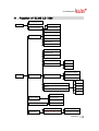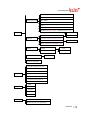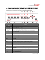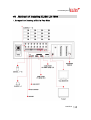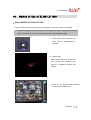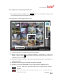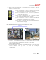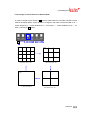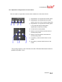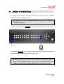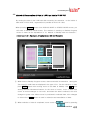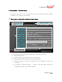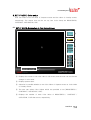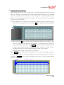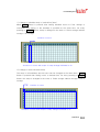
1
LeadTech Crop. ELiSS LD-1600 USER MANUAL 16CH Color Digital Video Recorder Linux DVR System Copyright ⓒ 2003 LeadTech Corp. All rights reserved. The contents of this User’s Manual shall not be reproduced arbitrarily without prior approval. The product of this User’s Manual may be modified without advance notice for the reasons of upgrading, etc. The trademarks mentioned in this User’s Manual are registered trademark and unique trademark of each relevant company. Please contact LeadTech Corporation for any unclear matters or errors to be corrected in the contents of this User’s Manual. Introducing DVR (Digital Video Recorder) The D.V.R. (Digital Video Recorder) system which overcomes weak point of conventional CCTV system where there inconvenient to operate with lots of restrictions. DVR system converts and records video images from conventional analog CCTV camera for extended period of time with real-time surveillance. DVR systems, not like conventional CCTV system which just records incoming video images but single DVR system can be incorporated with various external components (ex. Thermal Detector, Infrared Sensor, Shock Sensor, Door Sensor, light, access control and etc.) and self contained Motion detection feature which is with no doubt most integrated surveillance system ever. Especially, now a days not like systems from the past which operates independently from each other Number of systems incorporates as an network which makes unified system management and surveillance possible and also where there is internet access available it can be viewed and controlled from remote places in real-time. To construct networks of surveillance system requires DVR system which is a must. FCC ID No. : P8ZSECUMESH400 This device complies with part 15 of the FCC Rules. Operation is subject to the following two conditions: (1)This device may not cause harmful interference, and (2) this device must accept any interference deceived, including interference that may cause undesired operation. LeadTech 2 Linux DVR System This User’s Manual contains the following contents. Matters to note in installing ELiSS LD-1600 Name and function of each part of ELiSS LD-1600 Method of installation of ELiSS LD-1600 and connection of related equipment Method of using and setting of ELiSS LD-1600 Product specifications of ELiSS LD-1600 Repair of trouble and checking procedures, etc. of ELiSS LD-1600 The users who handle ELiSS LD-1600 are requested to pay attention to the matters to be noted after reading the User’s Manual prior to its use. LeadTech 3 Linux DVR System Contents of User’s Manual I . MATTERS TO BE NOTED.......................................................................................................9 II . COMPOSITION OF ELISS LD-1600 PRODUCT ............................................................... 10 III . MAJOR FEATURES OF ELISS LD-1600.......................................................................... 11 IV . FUNCTION OF ELISS LD-1600 ........................................................................................12 V . NAME AND FUNCTION OF EACH PART OF ELISS LD-1600......................................... 14 1. Name and Function of Each Part of Front Operating Panel .......................................... 14 2. Name and Function of Each Part of Rear Side Connection Terminal ........................... 15 VI . METHOD OF INSTALLING ELISS LD-1600 .................................................................... 16 1. Composition Drawing of Entire Rear Side....................................................................... 16 VII . METHOD OF USE OF ELISS LD-1600 ........................................................................... 17 1. Power ON/OFF of ELiSS LD-1600 .....................................................................................17 2. DISPLAY MODE(Monitor Mode) ........................................................................................18 2.1. Explanation of DISPLAY MODE Screen........................................................................ 18 ( Refer to p. Change of screen division.) .................................................................................... 18 2.2. Explanation of Contents Displayed on Each Screen (The case when OSD setting is ON) .............................................................................................................................................. 19 2.3. Conversion to Display Mode from Other Mode ............................................................. 20 2.3.1. Conversion to Display Mode from Search Mode .................................................................20 2.3.2. Conversion to Display Mode from Setup Mode ...................................................................20 2.3.3. Conversion to Display Mode from PTZ MODE...................................................................20 2.4. Change of Screen Dividing from Display Mode............................................................. 21 2.5. Automatic Channel Switching Function and TV OUT.................................................... 22 2.6. Conversion of Camera Channel from DISPLAY MODE Screen.................................... 22 LeadTech 4 Linux DVR System 2.7. Conversion of camera channel from DISPLAY MODE screen ...................................... 22 2.7.1. Conversion of Camera Channel from Screen Divided into 9 ...............................................23 2.7.2. Conversion of Camera Channel from Screen Divided into 8 ...............................................24 2.7.3. Conversion of Camera Channel from Screen Divided into 4 ...............................................25 2.7.4. Conversion of Camera Channel from Full Screen................................................................26 2.8. Real Time Storage in DISPLAY MODE ......................................................................... 27 3. SEARCH MODE(RETRIEVAL MODE) ................................................................................28 3.1. Explanation of Search Mode (RETRIEVAL MODE) Screen .......................................... 28 3.2. General Search.............................................................................................................. 29 3.2.1. Method of General Search....................................................................................................29 3.2.2. Regeneration of Generally Searched Data............................................................................30 3.2.3. Explanation of Data Regeneration Screen ............................................................................30 3.2.4. Explanation of Contents Displayed on Each Regeneration Screen ......................................31 3.2.5. Change of Screen Division of Search Mode.........................................................................32 3.2.6. Conversion of Camera Channel from Search Mode .............................................................33 3.2.7. Explanation of Regeneration Function Button .....................................................................34 3.3. Event Search ................................................................................................................. 35 3.3.1. Explanation of Event Search Screen.....................................................................................35 3.3.2. Method of Event Search .......................................................................................................36 3.3.3. Regeneration of Event-Searched Data..................................................................................37 3.3.4. Data Regeneration Screen ....................................................................................................37 3.3.5. Search of Other Date from Event Search Screen..................................................................37 3.4. SEARCH MODE-JPEG BACKUP ................................................................................. 38 VIII . BACKUP OF STORED DATA .........................................................................................39 1. Explanation of Backup Initial-Screen...............................................................................40 2. Explanation of Backup Progress Screen......................................................................... 41 3. Explanation of Backup Method of Stored Data ............................................................... 43 3.1. Explanation of Backup Method with LDV Extension ..................................................... 43 3.2. Explanation of Backup Method with AVI Extension ....................................................... 45 3.3. Method of Regeneration of Data in USB Hard disk in ELiSS DVR ............................... 48 IX . SETUP METHOD OF ELISS LD-1600 ..............................................................................50 LeadTech 5 Linux DVR System 1. Setup Mode .........................................................................................................................50 2. Input of Admin’s Password ...............................................................................................50 2.1. Explanation of Admin’s Password Input Screen ............................................................ 50 2.2. Method of Password Input ............................................................................................. 51 2.3. Conversion to Other Screen .......................................................................................... 52 3. Setup Mode Initial-Menu Screen .......................................................................................53 3.1. Explanation of Setup Mode-Initial Menu Screen ........................................................... 53 3.2. Selection of Menu from Setup Mode ............................................................................. 54 4. Setup Mode – General Setup.............................................................................................55 4.1. Setup Mode – Explanation of General Setup Screen.................................................... 55 4.2. Setup Mode – Selection of General Setup Menu .......................................................... 56 4.3. Changing Password....................................................................................................... 57 4.4. Channel Switching Setup and TV OUT ......................................................................... 58 4.5. OSD Setup.....................................................................................................................59 4.6. Setup of Rebooting ........................................................................................................ 60 4.7. Date Setup .....................................................................................................................61 4.8. Movement to Initial Menu Screen of Setup Mode from General Setup Screen ............ 62 5. Setup Mode – Camera Setup.............................................................................................63 5.1. Setup Mode – Explanation of Camera Setup Screen.................................................... 63 5.2. Setup Mode – Designation of Camera from Camera Setup Initial-Screen.................... 64 5.3. Changing Camera ID ..................................................................................................... 65 5.4. Setup of Frame Rate ..................................................................................................... 66 5.5. Setup of Video type ....................................................................................................... 67 5.6. Setup of PTZ Type / ID .................................................................................................. 68 5.7. Setup of the Status of Recording................................................................................... 69 5.8. Setup of Motion.............................................................................................................. 70 5.8.1. Setup of Motion Sensitivity ..................................................................................................70 5.8.2. Setup of Motion Continuance Time......................................................................................71 5.8.3. Setup of Motion Sphere Display...........................................................................................71 5.9. Setup of Compressed Image Quality............................................................................. 72 5.10. Setup of Alarm ............................................................................................................. 73 5.11. Setup of Resolution...................................................................................................... 74 5.12. Movement to Initial Menu Screen of Setup Mode from Camera Setup Screen .......... 75 LeadTech 6 Linux DVR System 6. SETUP MODE-Color setup ................................................................................................76 6.1. SETUP MODE-Explanation of Color Setup Screen ...................................................... 76 6.2. Explanation of Color Setup Method............................................................................... 77 7. SETUP MODE – Motion Recording Setup........................................................................ 78 7.1. Motion Recording........................................................................................................... 78 7.1.1. Execution of Motion Recording ...........................................................................................78 8. SETUP MODE – Motion Recording Sphere Setup........................................................... 81 8.1. Explanation of Motion Sphere Setup Screen................................................................. 81 8.2. Setup Method of Motion Sensing Sphere ...................................................................... 82 8.3. Movement to Initial Menu Selection Screen of Setup Mode from Motion Setup ........... 85 Screen................................................................................................................................... 85 9. SETUP MODE – Schedule..................................................................................................87 9.1. SETUP MODE – Explanation of Schedule Screen........................................................ 87 9.2. SETUP MODE – Designation of Camera at Schedule Setup Screen ........................... 88 9.3. Method of Schedule Setup ............................................................................................ 89 9.4. Setup of Application Scope of Schedule........................................................................ 91 9.5. Movement from Schedule Setup Screen to Initial Menu Selection Screen of SETUP MODE. .................................................................................................................................. 91 10. SETUP MODE – Network Setup ......................................................................................92 10.1. SETUP MODE-Explanation of Network Setup Screen................................................ 92 10.2. Setup of DHCP (Method of IP Address Setup)............................................................ 93 10.3. Change of IP Setup Value ........................................................................................... 94 10.4. Change of Net Mask Setup Value ............................................................................... 95 10.5. Change of Gateway Setup Value ................................................................................ 96 10.6. Change of Port Setup Value ........................................................................................ 97 10.7. Change of Setup Value of the Number of Simultaneous Users .................................. 98 10.8. Change of Setup Value of Network Image quality ....................................................... 99 10.9. Movement to Menu Selection Initial-Screen of Setup Mode from Network Setup Screen .......................................................................................................................................... 100 11. SETUP MODE – Sensor Setup..................................................................................... 101 11.1. SETUP MODE-Sensor Setup Screen...................................................................... 101 11.2. Method of Designation of Sensor Intended to Set up .............................................. 102 LeadTech 7 Linux DVR System 11.3. Change of Setup in Sensor Menu............................................................................ 103 11.4. Setup of Recording Continuance Time .................................................................... 104 11.5. Setup of Recording (Camera) .................................................................................. 105 11.6. Alarm Setup.............................................................................................................. 106 11.7. Movement to Menu Selection Initial-Screen of Setup Mode from Sensor Setup Screen .....................................................................................................................................…..106 12. SETUP MODE – Alarm Setup....................................................................................... 108 12.1. Explanation of Alarm Setup Screen......................................................................... 108 12.2. Designation of Alarm to be Set up ........................................................................... 109 12.3. Change of Setup in Alarm Menu.............................................................................. 110 12.4. Setup of Alarm Continuance Time ........................................................................... 111 12.5. Movement to Menu Selection Initial-Screen of Setup Mode from Alarm Setup Screen… .......................................................................................................................................... 111 13. SETUP MODE – Parallel Port Setup............................................................................ 113 13.1. Explanation of Parallel Port Setup Screen .............................................................. 113 13.2. Method of Parallel Port Setup.................................................................................. 114 14. PTZ CONTROL MODE .................................................................................................. 115 14.1. Explanation of PTZ Control Mode Screen ............................................................... 115 14.2. Selection of PTZ Control Mode Menu ..................................................................... 116 14.3. PTZ Camera Control Method .................................................................................. 117 14.3.1. Control of PAN/TILT......................................................................................................117 14.3.2. Control of ZOOM...........................................................................................................117 14.3.3. Control of FOCUS..........................................................................................................118 14.3.4. Control of LIGHT...........................................................................................................118 14.3.5. Control of Power ............................................................................................................119 X . PRODUCT SPECIFICATIONS FOR ELISS LD-1600 .................................................... 120 XI . TROUBLESHOOTING GUIDE ...................................................................................... 121 X . QUALITY WARRANTY .................................................................................................. 123 LeadTech 8 Linux DVR System I . Matters to be Noted Matters to be Noted Turn off the power of EliSS LD-1600 without fail before the installation. The persons other than professional installer should not open the cover of the case of this product at their own discretion. When verifying internal part of this product for system upgrade or repair of trouble, please ask to the place of purchase without fail. When installing this product, maintain approximately 15cm of distance from other nearby equipment. Be careful not to apply impact or shaking when ELiSS LD-1600 is moved or in operation. Do not install at the place where there is strong magnetism or radio wave. surface of wall for smooth radiation of heat. Be attentive no conductive material is put inside the cooling ventilation hole. Please avoid installing at the places of high temperature such as nearby direct sunlight or heater. Please avoid installing at the places where are extremely cold or highly humid. Before connecting the power, check the using power of AC100~240V 50/60Hz without fail. This unit is designed for indoor use. Operating ambient temperature must not range beyond (0℃~+40℃) LeadTech 9 Linux DVR System II . Composition of ELiSS LD-1600 Product Unpack the packaging of ELiSS LD-1600 and place ELiSS LD-1600 at the place to install. (Refer to installation safety information before the installation.) Check the contained material of the product before the installation. - Main body (ELiSS LD-1600) - User’s Manual - Ac power cable for use with ELiSS - ELiSS CASE Handle - EyeLinker program CD (Option) - Remote Control Contents Main composition of ELiSS DVR External feature of product Contents User’s manual Network Client S/W CD(option) Remote Control External view of Power cable ELiSS CASE handle. products ※ Since EyeLinker program CD is an optional item, it may not be contained in the contents of the package. LeadTech 10 Linux DVR System III . Major Features of ELiSS LD-1600 1. Accepted all merits of Window type DVR and Stand-Alone type DVR/removed demerits 1.1. Easiness of Operation Since the product is operated by button panel without using keyboard/mouse, the operating system is simple and intuitive, and anyone can easily operate. 1.2. Outstanding Stability As a Linux-based system, it could be bootable by flash memory instead of HDD, and the product is very stable. Since the Boot-Up time is very short, all booting works are completed within 4~50 seconds, and start capture. Its Boot-Up speed is similar to that of ordinary times and it recovers date through journaling even during the disasters such as sudden power failure or shutdown, etc. 1.3. Strong Network Function Remote monitor and control is possible using exclusive Client Program. 1.4. Variety of Customizing Function 1.5. Convenient Upgrade When only flash memory is changed, future upgrade to new version is easy. 2. Monitor Divided monitor by each 8CH camera channel, movement monitor function, movement storage sphere setting function are possible, and storage by time band (schedule storage), multi resolution support, etc. 3. Search Preceding Play, Stop, Fast Forward, Fast Backward, by each 1frame, jump search by each 5 minute to forward and backward, event search, etc. 4. Setup Setup by each of 16 cameras, storage schedule setup, network setup, setup by each sensor, setup by each alarm, etc. 5. Use of Self-developed XMB Codec (MPEG4 base) When recorded at almost similar screen quality level with actual screen, it shows compression function as excellent as an average of about 2KB per each 1 frame. LeadTech 11 Linux DVR System IV . Function of ELiSS LD-1600 Overlay Mode * MODE General search Search Mode Event search Password Password re-setup General setup Channel switching OSD Rebooting Date setup ID (Camera No) Frame rate Storage status PTZ type/ID Storage Storage status Schedule Not stored Sensitivity setup * SETUP Camera setup Motion setup Continuous time Display ALARM 1 Compression Image Select up to 1~5) ALARM 2 Alarm ALARM 3 Resolution ALARM 4 OFF BRIGHTNESS Color setup CONTRAST SATURATION Motion sphere setup Schedule HUE Schedule setup Entire storage 스케줄 적용범위 설정 Individual storage LeadTech 12 Linux DVR System Use of DHCP IP Network setup Net Mask Gateway Port Number of simultaneous users Network image quality (Select up to 1~5) * SETUP N/O Setup Sensor N/C Storage continuous-time setup Storage Camera setup Alarm (Select up to ALARM 1~4) Alarm Setup N/O Continuous time N/C Parallel port setup Digital out System manager Screen divided into 16 Screen divided into 13 Screen divided into 9 * DIV Screen divided into 8 Screen divided into 6 Screen divided into 4 Full screen PAN * PTZ TILT FOCUS LIGHT POWER * BACKUP Back-up with LDV extension Back-up with AVI extension LeadTech 13 Linux DVR System V . Name and Function of Each Part of ELiSS LD-1600 1. Name and Function of Each Part of Front Operating Panel Name of Operating Function Button ① USB Port ② 리모콘 센서 - Terminal for USB connection - 리모콘 신호를 수신하는 곳 입니다. ③ Camera Select (01~16) - When pressing the camera channel button desired among camera channel of 01~16 pieces, then the concerned screen is shown in full screen. - Used as number-entering key on password input (The number 10 channel button is 0 on password input) ④ Search - Converts the screen into SEARCH MODE and DISPLAY MODE ⑤ SETUP - Converts the screen into SETUP MODE - Change division mode of the screen into 16 division→13 division→9 division→8 division→6 division→4 division→Full screen mode. ⑥ DIV ⑦ CANCEL - Used when canceling setup contents. ⑧ PTZ - Used when entering PAN/TILT Operation MODE. ⑨ BACKUP - Used when entering BACKUP MODE. ⑩ ◀◀ ⑪▶ ⑫ ▶▶ - If you press this on retrieval of recorded data, reverse direction high-speed search is executed. - If you press this once, recorded data is regenerated. Pressing once more stops the screen being regenerated temporarily. - If you press this on regeneration of recorded data, right direction high-speed search is executed. In case of during temporary stop. Move forward by one frame. ⑬■ - Converts MODE into DISPLAY MODE. ⑭ ●REC - Executes total storage in DISPLAY MODE regardless of schedule. ⑮◀ 16 ▶ ○ 17 ▲ ○ 18 ▼ ○ 18 ENTER ○ 16 ▶ ○ - Moves the location of cursor to the left /- Search is made moving backward by 5 minutes in Search Mode. - Moves the location of cursor to the right /- Search is made moving forward by 5 minutes in Search Mode. - Moves up the location of cursor /- Used as CAMER CHANGE(+) button - Moves down the location of cursor /- Used as CAMER CHANGE(-) button - Used when selecting and storing value. - Turns ON/OFF ELiSS LD-1600. LeadTech 14 Linux DVR System 2. Name and Function of Each Part of Rear Side Connection Terminal VI . Name of Connection Terminal Function ① Power AC 100V ~ 240V, 50/60Hz ② CAM01~CAM12 Camera input terminal(12ch) ③ SENSOR INPUT Terminal receiving input of 16 sensors. ④ ALARM OUTPUT Terminal for the output of 4 alarms. ⑤ MOUSE Terminal for the connection of mouse. ⑥ keyboard Terminal for the connection of keyboard. ⑦ COM1 COM1 Port for the control of PTZ. ⑧ USB port Terminal for the connection of USB. ⑨ TV OUT 1 TV OUT terminal (CAPTURE) ⑩ VGA Terminal for the connection of VGA monitor. ⑪ TV OUT 2 TV OUT terminal (OVERLAY) ⑫ SENSOR ALARM Terminal Terminal for connecting SENSOR, ALARM ⑬ Ethernet Terminal for the connection of 10/100 network LeadTech 15 Linux DVR System VII . Method of Installing ELiSS LD-1600 1. Composition Drawing of Entire Rear Side LeadTech 16 Linux DVR System VIII . Method of Use of ELiSS LD-1600 1. Power ON/OFF of ELiSS LD-1600 Power of DVR must be turned ON after all installation of ELiSS LD-1600 is completed. Check the voltage of input power before turning ON power switch. Using after converting power conversion switch on the rear side of ELiSS to the matching voltage. 1) Press power switch of ELiSS LD1600 long for approximately 4 seconds. 2) Initial Screen - When power switch of ELiSS LD1600 turned ON, following logo picture is displayed showing the product. 3) Enter to the Display Mode (Monitor mode) screen divided into 16. LeadTech 17 Linux DVR System 2. DISPLAY MODE(Monitor Mode) DISPLAY MODE(Monitor Mode) performs the function of showing the image in real time and moving image relayed through installed camera. When power of ELiSS LD-1600 turns ON, the user enters into Display Mode Screen. 2.1. Explanation of DISPLAY MODE Screen ③ ④ ⑤ ⑦ ② ① ⑧ ① As a DISPLAY sphere, present picture is the screen divided into 16. ( Refer to p. Change of screen division.) ② Indicates present MODE. Present MODE is DISPLAY MODE. ③ Indicates present date and time. ④ Indicates storage status of each of 16 cameras by Icon. Icon that indicates concerned camera is storing all. Icon that indicates concerned camera is storing motion. ⑤ The operating sensors among 16 sensors shine with yellow light. ⑥ The operating alarms among 4 alarms shine with red light. ⑦ Client (EyeLinker Program) 에서 접속중인 user 수를 표시합니다. ⑧ 현재 ELiSS의 총 저장용량과 사용중인 용량을 표시합니다. LeadTech 18 Linux DVR System 2.2. Explanation of Contents Displayed on Each Screen (The case when OSD setting is ON) SETUP-In general setup, when you change OSD setup to ON, setup value by each camera channel is displayed on the screen. The contents displayed on the screen are as follows. SETUP-When you change OSD setup to OFF in general setup, the following contents are not displayed on the screen. ( Refer to p.4.5 OSD setup) <Expansion> CAM ID ③ R ① <DISPLAY MODE of Screen divided into 16> ① M P S ② <Contents displayed on each screen> Camera ID : Camera ID that image is flashed is marked at upper left side of concerned screen. ID of each individual camera can be set up at the discretion of user at SETUP MODE. (Refer to p: 5.3. Camera ID Change) ② Storage status and setup status by each camera channel are shown in alphabet initials. R : Initial indicating that concerned camera is executing entire storage. M : Initial indicating that concerned camera is executing motion storage. S : Initial indicating that the sensor is in operation. P : Initial indicating that concerned camera is set up with pan/tilt camera. ( Refer to PTZ type/ID setup in p.66: 5.6.) ※ What is PAN/TILT Camera? Pan/TILT is a rotator that rotates the camera up/down and left/right, and it is a device for the expansion of monitor scope. It is a device to eliminate the area that camera image can not catch (dead angle area). The camera equipped with such PAN/TILT is named as Pan/Tilt Camera. LeadTech 19 Linux DVR System ③ Indication of Motion Sphere : When moving is sensed in the set area while in setup as motion storage, sensed area is changed to blue color. (Refer to Motion setup on p.68: 5.8..) ※ In camera setup, if Display of Motion Setup is set to OFF, no sphere indication is shown on the screen. 2.3. Conversion to Display Mode from Other Mode 2.3.1. Conversion to Display Mode from Search Mode If you press MODE button ( ) from Search Mode, conversion to DISPLAY MODE 로 is made. 2.3.2. Conversion to Display Mode from Setup Mode When CANCEL button ( ) is pressed from initial menu screen of Setup Mode, conversion to Display Mode is made. 2.3.3. Conversion to Display Mode from PTZ MODE When ENTER / CANCEL button( / ) is pressed from PTZ Mode, conversion to Display Mode is made.. LeadTech 20 Linux DVR System 2.4. Change of Screen Dividing from Display Mode You can change screen dividing mode by using DIV button. Each one pressing of DIV button converts the screen in the order of 16-division screen → 13-division screen → 9division screen → 8-division screen → 6-division screen→ 4-division screen→ Full screen → 16-division screen → 13-division screen.……. CAM1 2 3 4 5 6 7 9 10 13 14 CAM1 2 8 5 6 11 12 8 15 16 10 11 CAM1 2 7 12 13 <13 division screen > 2 3 4 5 6 7 8 9 < Full screen > CAM1 4 9 <16 division screen > CAM1 3 < 9 division screen > CAM1 2 CAM1 2 3 3 3 4 4 4 5 6 5 <4 division screen > < 6 division screen > 6 7 8 < 8 division screen > LeadTech 21 Linux DVR System 2.5. Automatic Channel Switching Function and TV OUT Automatic Channel Switching Function is the function that automatically change camera channel shown on the screen in case of screen divided into 13, screen divided into 9, screen divided into 8, screen divided into 6, screen divided into 4 and Full screen. When channel switching time interval is set up, camera channel on the screen automatically changes at the set time interval. Time interval of channel switching can be set at the discretion of user in setup mode. (Refer to Channel Switching Setup and TV OUT on p.56: 4.4.) When common analog TV is connected to TV OUT terminal at connection terminal in the rear side of ELiSS LD-1600, same TV screen as the screen of ELiSS LD-1600 is output. Setup of channel switching is equally applied to TV OUT screen. 2.6. Conversion of Camera Channel from DISPLAY MODE Screen When a user presses any desired channel button in DISPLAY MODE by using 16 Camera Select buttons located on the front side of EliSS LD-1600, such camera channel is directly converted into Full screen so that the user may monitor the screen. If you press the desired camera channel, the relevant camera screen is converted into Full screen mode so that you may see. If you enter password, Camera Select button may be used as number-entering button. At the time of password input, number 10 channel button is recognized as ‘0’. 2.7. Conversion of camera channel from DISPLAY MODE screen This is a function to see the channel presently not shown in screen divided into 9/screen divided into 8/screen divided into 4/Full screen mode. To convert camera channel shown on the screen in EliSS LD-1600, use ▲/▼button among Direction Movement buttons. ▲button increases (+) channel of the camera and ▼button decrease (-) channel of the camera. Conversion of camera channel is impossible in case of screen divided into 13 and screen divided into 6. LeadTech 22 Linux DVR System 2.7.1. Conversion of Camera Channel from Screen Divided into 9 Firstly, set the division of the screen to the screen divided into 9 using DIV button. To convert camera channel which is shown on the screen, use ▲/▼button among Direction Movement buttons. ▲button increases (+) channel of the camera and ▼button decreases (-) channel of the camera. 2) ▲button increases (+) channel of the camera and ▼button decreases 1) Convert to screen divided into 9 by (-) channel of the camera. pressing DIV button. CAM1 2 3 4 5 6 7 8 9 ① CAM8 9 10 11 12 13 14 15 16 ② ① This is the direction in which camera channel is converted by every 1 pressing of CAMERA CHANGE(+) button among Direction Movement buttons from the screen divided into 9. (Converted in the order of CAM1~CAM9 screen→ CAM8~CAM16 screen→ CAM1~CAM9 screen→ CAM8~CAM16 screen→ …….) ② This is the direction in which camera channel is converted by every 1 pressing of CAMERA CHANGE(-) button among Direction Movement buttons from the screen divided into 9. (Converted in the order of CAM1~CAM9 screen→ CAM8~CAM16 screen→ CAM1~CAM9 screen→ CAM8~CAM16 screen → …….) LeadTech 23 Linux DVR System 2.7.2. Conversion of Camera Channel from Screen Divided into 8 Firstly, set division of the screen to the screen divided into 8 by using DIV button. To convert camera channel shown on the screen, use ▲/▼button among Direction Movement buttons in case of EliSS LD-1600. ▲button increases (+) channel of the camera and ▼button decreases (-) channel of the camera. . 2) ▲button increases (+) 1) Convert into the screen divided into 8 by camera channel and ▼button decreases (-) camera channel. pressing DIV button. CAM1 5 2 6 7 ① CAM9 10 3 11 4 12 8 ② 13 14 15 16 ① This is the direction in which camera channel is converted by every 1 pressing of ▲button among Direction Movement buttons from the screen divided into 8. (Converted as CAM1~CAM8 screen→CAM9~CAM16 screen→CAM1~CAM8 screen→CAM9~CAM16 screen→ …….) ② This is the direction in which camera channel is converted by every 1 pressing of ▼button among Direction Movement buttons from the screen divided into 8. (Converted as CAM1~CAM8 screen→ CAM1~CAM16 screen→CAM1~CAM8 screen→CAM9~CAM16 screen→ …….) LeadTech 24 Linux DVR System 2.7.3. Conversion of Camera Channel from Screen Divided into 4 Firstly, set division of the screen to the screen divided into 4 by using DIV button. To convert camera channel shown on the screen, use ▲/▼button among Direction Movement buttons in case of ELiSS LD-1600. ▲button increases (+) camera channel and ▼button decreases (-) camera channel.. 2) ▲button increases (+) 1) Convert into screen divided into 4 by camera channel and ▼button decreases (-) camera channel. pressing DIV button. CAM1 2 3 4 ① CAM9 11 10 12 ② CAM13 14 CAM13 15 16 15 14 16 ① This is the direction in which camera channel is converted by every 1 pressing of ▲button among Direction Movement buttons from the screen divided into 4. (Converted in the order of CAM1~CAM4 screen → CAM5~CAM8 screen → CAM9~CAM 12 → CAM13~CAM 16 screen →…….) ② This is the direction in which camera channel is converted by every 1 pressing of ▼button among Direction Movement buttons from the screen divided into 4. (Converted in the order of CAM1~CAM4 screen→ CAM13~CAM16 screen → CAM9~CAM12 screen → CAM5~CAM8 screen →…….) LeadTech 25 Linux DVR System 2.7.4. Conversion of Camera Channel from Full Screen Firstly, set division of the screen to Full screen by using DIV button. To change camera channel shown on the screen, use ▲/▼button among Direction Movement buttons in case of ELiSS LD-1600. ▲button increases (+) camera channel and ▼button decreases (-) camera channel. 2) ▲button increases (+) 1) Convert into Full screen by pressing DIV camera channel and ▼button decreases (-) camera channel. button. CAM1 ① CAM2 CAM16 ② ① This is the direction in which camera channel is converted by every 1 pressing of ▲button among Direction Movement buttons from Full screen . (Converted in the order of CAM1 Full screen→ CAM2 Full screen→ CAM3 Full screen→…… →CAM15 Full screen→ CAM16 Full screen→ CAM1 Full screen→…….) ② This is the direction in which camera channel is converted by every 1 pressing of ▼button among Direction Movement buttons from Full screen. (Converted in the order of CAM1 Full screen→ CAM16 Full screen→ CAM15 Full screen→…… → CAM3 Full screen → CAM2 Full screen → CAM1 Full screen→……) LeadTech 26 Linux DVR System 2.8. Real Time Storage in DISPLAY MODE In ELiSS LD-1600, you can make real time storage in monitor mode. To do that, use ●REC button located on the front side of ELiSS LD-1600 in DISPLAY MODE screen. If you press ●REC button in Monitor Mode, it stores all the video displayed on the screen real time. Even if set up in schedule, it executes all the video. The stored date can be regenerated in the method of general search in Search Mode. LeadTech 27 Linux DVR System 3. SEARCH MODE(RETRIEVAL MODE) Search Mode is a mode that can search/regenerate recorded image by date, by time. It is converted to Search Mode when pressing MODE button of front side of ELiSS from Display Mode. Search method has General Search and Event Search. 3.1. Explanation of Search Mode (RETRIEVAL MODE) Screen ⑤ ② ⑥ ⑦ ④ ③ ① Indicates Present Mode. Present Mode is Search Mode. ② Indicates date and time to search, and the user can personally select the date and time to search. ③ Calendar of the month to search. The date marked in red color is the date that has recorded data and the date marked in white color is the date without recorded data. ④ The user can search selecting one between general search and event search. ⑤ Indicates present date and time. ⑥ Indicates existing or none of recorded data with icon by each camera channel at selected time/date. Indicates existing of recorded data in concerned channel at selected time/date Icon indicates no recorded data in concerned channel at selected time/date. ⑦ Indicates with icon the status that recorded data is being retrieved presently. LeadTech 28 Linux DVR System 3.2. General Search General Search is a function that allows the user to select the time/date desired and search/regenerate entire stored data at such selected time. 3.2.1. Method of General Search ② ① ① Place cursor at general search button using ▲/▼ button among Direction Movement buttons located in the front side of ELiSS. When cursor is placed, general search button is lit with red light from blue light. ② When the general search button shines with red light, press again ▶ button among Direction Movement buttons located in the front side of ELiSS. Then the location of cursor moves to date selection window. Initial cursor is located at the Year. • ◀/▶ button among Direction Movement buttons : Moves the location of the cursor right and left. • ▲/▼ button among Direction Movement buttons Changes the figures of the place where the cursor is located ③ Press ENTER button when date/time selection is completed. If there is no stored data on selected time/date, following message is shown.. LeadTech 29 Linux DVR System 3.2.2. Regeneration of Generally Searched Data After selecting intended time/date, press ENTER button. Then conversion is made to the screen that regeneration of actual data can be done. 3.2.3. Explanation of Data Regeneration Screen ④ ⑥ ⑤ ① ② ③ ① Indicates present mode. Present mode is SEARCH MODE. ② Sphere where recorded data of searched time/date is regenerated. To change the division of screen, press DIV button located at front side of ELiSS. Division of screen is changed by each 1 pressing. ③ ‘NO DATA’ message is shown in case of the camera channel with no recorded data at searched time/date. ④ Time/date when the Image of the screen was taken is displayed. ⑤ Existence or none of recorded data by each camera channel is displayed as icon. This icon means that concerned channel has recorded data at selected time/date. This icon means that concerned channel has no recorded data at selected time/date. LeadTech 30 Linux DVR System ⑥ Display present regenerating status of recorded data by icon. Displayed in red color according to reproducing status. ⓐ ⓑ ⓒ ⓓ ⓔ ⓐ If this icon is displayed in red color, it means that recorded data are being regenerated at right direction and right speed. ⓑ If this icon is displayed in red color, it means that regeneration of recorded data is discontinued. ⓒ When this icon is displayed in red color, it means that recorded data are regenerated at right direction and speed. ⓓ If this icon is displayed in red color, it means that recorded data are regenerated at reverse direction and fast speed. ⓔ When this icon is displayed in red color, it means that the time of regenerating data is changing. 3.2.4. Explanation of Contents Displayed on Each Regeneration Screen <Expansion> ② 17:01:19.00 ① ① Camera ID : Camera ID that image is shined is displayed at left side of concerned screen. ID of each camera can be set at user’s discretion in Setup Mode. (Refer to p. Setup of camera ID.) ② Recorded time of the screen being retrieved: Recorded time of the image being retrieved is displayed on the right bottom of the screen. Type of marking is <HH:MM:SS.SS>. LeadTech 31 Linux DVR System 3.2.5. Change of Screen Division of Search Mode In order to change screen division, DIV button is used located on front side of ELiSS in same manner as Display Mode. Screen division is changed in the order of screen divided to 16 → screen divided to 9 → screen divided into 4 → Full screen →…screen divided into 16 →…for each 1 pressing of DIV button. DIV button을 눌러 화면분할 모드를 전환합니 다. CAM1 2 3 4 5 6 7 8 9 10 11 12 13 14 15 16 CAM1 <Divided into 16> CAM1 < Full screen > 2 3 4 5 6 7 8 9 <Divided into 9> CAM1 2 3 4 <Divided into 4> LeadTech 32 Linux DVR System 3.2.6. Conversion of Camera Channel from Search Mode This function is to watch camera channel which is not watched at present in 9-division screen/4-division screen/Full screen mode. In order to convert camera seen on the screen, use ▲/▼button among Direction Movement buttons in the same way as channel conversion. ▲button increases (+) camera channel and ▼button decreases (-) camera channel. (Refer to p. The conversion of camera channel from Display Mode) (1) Conversion of Camera Channel from 9-Division Screen Mode For every 1 pressing of ▲button among Direction Movement buttons, camera channel is converted in the order of CAM1~CAM9 channel screen→CAM8~CAM16 channel screen→CAM1~CAM9 channel screen→……. For every 1 pressing of ▼button among Direction Movement buttons, camera channel is converted in the order of CAM1~CAM9 channel screen→CAM8~CAM16 channel screen→CAM1~CAM9 channel screen→……. (2) Conversion of Camera Channel from 4-Division Screen Mode For every 1 pressing of ▲button among Direction Movement buttons, camera channel is converted in the order of CAM1~CAM4 channel screen→CAM5~CAM8 channel screen→CAM9~CAM12 channel screen→CAM13~CAM16 channel screen. For every 1 pressing of ▼button among Direction Movement buttons, camera channel is converted in the order of CAM1~CAM4 channel screen→CAM13~CAM16 channel screen→CAM9~CAM12 channel screen→CAM5~CAM8 channel screen →……. (3) Conversion of camera channel from Full Screen Mode For every 1 pressing of ▲button, camera channel is converted in the order of CAM1 channel screen→CAM2 channel screen→CAM3 channel screen→……→CAM15 channel screen→CAM16 channel screen→CAM1 channel screen→CAM2 channel screen→ . For every 1 pressing of ▼button among Direction Movement buttons, camera channel is converted in the order of CAM1 channel screen→CAM16 channel screen→CAM15 channel screen→……→CAM2 channel screen→CAM1 channel screen→CAM16 channel screen→CAM15 channel screen→…… ※ Since all of 16CH are displayed on one screen in case of screen divided into 16, it is meaningless to convert camera channel by pressing ▲/▼button among Direction Movement buttons. LeadTech 33 Linux DVR System 3.2.7. Explanation of Regeneration Function Button This is to explain on regeneration function button located on the front side of ELiSS. ① Regenerates in the right direction at fast speed. ② Regenerates in the right direction at normal speed. Press once more to stop this temporarily. ③ Regenerates in the right direction at fast speed. ① ② ③ ④ If you press this during its being static, regeneration is made by one frame. ④ Converts this to Overlay Mode. ⑤ Moves to 5 minutes before the time search is presently being made. ⑥ Moves to 5 minutes after the time search is presently being made. ⑦ Increases (+) camera channel shown on the screen. ⑧ Decreases (-) camera channel shown on the ⑤ ⑦ ⑧ ⑥ screen. ※ The moving function in the 5 minutes unit with 2 Direction Movement buttons is possible only within 1 hour. LeadTech 34 Linux DVR System 3.3. Event Search Motion storage is done when motion storage sphere is set and motion take place in such sphere. Event search allows the user to search by each camera channel for the stored data list through motion storage at intended time/date. 3.3.1. Explanation of Event Search Screen ⑥ ③ ④ ② ⑤ ① When event search is selected and entered into it, the above screen appears. ① Displays present mode. Present mode is Search Mode. ② The user can select at user’s own discretion between general search and event search. ③ Displays camera No. for event search. Camera No. can be changed by the user. ④ Displays time/date of search. Time/date of search can be changed by the user using Direction Movement button located on the front side of ELiSS. ⑤ This is a window that shows concerned time/date and event searched data on concerned camera in the form of list. ⑥ Displays current time/date. LeadTech 35 Linux DVR System 3.3.2. Method of Event Search ③ ② ④ ① ⑤ ① Position the cursor to event search using ▲/▼ button among Direction Movement buttons located on the front side of ELiSS between General Search and Event Search. When cursor is positioned, red light is lit on event search. ② After selecting Event Search, when you press ▶ button among Direction Movement buttons located on the front side of ELiSS, cursor appears in the camera channel selection window desired to search. Among Direction Movement buttons, when you use ▲ button, the number increases, and when you use ▼ button, the number decreases. ③ After selecting camera channel, Sensor and Motion can be selected using ▶ button among Direction Movement buttons. ▲/▼ button among Direction Movement buttons is used for selection. SENSOR means to search stored data when Sensor is operative, and Motion means to search motion-stored data. LeadTech 36 Linux DVR System ④ When selection is completed between MOTION/SENSOR, move the cursor to event search date setting window by pressing ▶ button located on the front side of ELiSS. In date setting window, ◀/▶button among Direction Movement buttons is used for the movement of cursor. ▲/▼ button among Direction Movement buttons is used for change of number. ⑤ When search time/date setting is completed, press ENTER button located on the front side of ELiSS. If searched data exist, the data are shown in the form of list. Move cursor to desired data using ▲/▼button among Direction Movement buttons. Move of cursor is displayed in red color. Selected data is regenerated when pressing ENTER button on the front side of ELiSS. 3.3.3. Regeneration of Event-Searched Data After designating one in event searched data list, when you press ENTER button located on the front side of ELiSS, the screen moves to data regeneration screen. 3.3.4. Data Regeneration Screen Same as general data regeneration screen. (Refer to ‘3.2.3. Data Regeneration’). Data regeneration function button also has same function as in general search regeneration. (Refer to 3.2.7 Regeneration Function) 3.3.5. Search of Other Date from Event Search Screen When you want to search on other date during the search of recorded data, press ENTER button on front side of ELiSS. Then camera date selection screen for event search appears. Method of selection is same as Camera Selection/Date Selection method as explained in ‘3.2.1. Event Search’. LeadTech 37 Linux DVR System 3.4. SEARCH MODE-JPEG BACKUP JPEG Backup is a function to backup while search is made, and stores in picture file of JPEG format by each 1 frame. ① Connect USB hard disk to USB Port. ② Execute General Search or Event Search. (Refer to p.: 3.2. General search. P. 3.3. Event search). ③ Indicate the screen of the target camera as 1 channel mode by using camera number from No. 1 to 16 located on the front side of ELiSS LD-1600. ④ If you press Regeneration (▶)button once again from the status in which searched screen is being regenerated, it stops tentatively. ⑤ If you press right direction fast regeneration (▶▶)button from the status in which searched screen regeneration stopped tentatively, proceed forward by 1 frame is possible, and press BACKUP button when intended frame appears. (Caution! ◀◀button does not proceed backward by each 1 frame.) ※ If pressing BACKUP button , frame of that moment appears as Stop Screen and proceed Backup even in process of regeneration, not ‘Tentative Stop’. ⑥ If data is stored in USB Hard disk, then the message ‘Stored in USB hard disk’ appears. In case it failed to store data, the message ‘Failed to store data in USB Hard disk’ appears. ⑦ Storage position of JPEG is under ‘/JPEG/’ directory, and stored in the name of same type as ‘ch01_2003070112_3022.15.jpg’ (No. 1 camera 12:30 hours 22.15 seconds July 1, 2003 frame). LeadTech 38 Linux DVR System IX . Backup of Stored Data By backing up stored data in USB Hard disk, users can watch the data at Windows environment of PC and ELiSS LD-1600. ※ JPEG Backup is possible in SEARCH MODE, and refer to P.38 : 3.4 SEARCH MODE-JPEG Backup. For backup of stored data, use BACKUP button located on the front side of ELiSS LD-1600. USB PORT When pressing BACKUP button from DISPLAY MODE and SEARCH MODE, it is converted to BACKUP MODE, and BACKUP MODE has two screens. ※ Check if ELiSS LD-1600 and USB Hand-disk are connected without fail before executing BACKUP. Before using, please connect USB Hard-disk to USB port of system after formatting USB Hard-disk from Window to FAT32. LeadTech 39 Linux DVR System 1. Explanation of Backup Initial-Screen ② ③ ⑤ ④ ① ① Indicates present mode. It is BACKUP MODE at present. ②, ③ Indicates time/date intended to search. User can set intended date of search at his own discretion. ④ This is calendar of the month intended to search. Data stored date is marked in red color, and the date data is not stored is marked in white color. ⑤ Storage is possible in two types. : When Storage is selected, backup can be done with ldv extension which is the type that can regenerate in ELiSS LD1600, and enters into backup progress screen. : When Storage(AVI Conversion) is selected, backup can be done converting to avi extension which is a type that can regenerate in moving image regeneration program which is common in window, and enters into backup progress screen. LeadTech 40 Linux DVR System 2. Explanation of Backup Progress Screen ③ ⑥ ④ ② ⑤ ① ① Indicates present mode. Present mode is BACKUP MODE. ② This is a window showing data information inside ELiSS LD-1600 Hard disk. If stored data exist in ELiSS-1600 on set date from backup initial-screen, the data appear as one list. If quantity of list exceeds one screen, scroll bar appears in the right side of the window. Type of appeared data is “yyyy(year) mm(month) dd(date) hh(time)_01(camera No. of recorded image).ldv”. ③ Button related with backup is located. : This button executes backup of the data inside ELiSS LD-1600 harddisk with USB hard-disk. : This button deletes the data inside ELiSS LD-1600 harddisk. : This button selects all data list appeared on ② screen. After pressing this button, backup or erasure can be executed. ④ Indicates progress process of backup, and indicates message related to backup. LeadTech 41 Linux DVR System ⑤ This is a window indicating data information in USB hard disk. If you selected on the backup initial-screen, all data list of “idv” format appears, and if you selected ‘AVI Storage’, all data list of “avi” format appears. If quantity of list exceeds one screen, scroll bar appears in the right side of window. Type of shown data is “yyyymmddhh_01(camera No. of recorded image).avi”. LeadTech 42 Linux DVR System 3. Explanation of Backup Method of Stored Data 3.1. Explanation of Backup Method with LDV Extension ① When pressing BACKUP button from DISPLAY MODE or SEARCH MODE screen, enters to BACKUP initial-screen. ② If you enter to BACKUP initial-screen for the first rime, there is cursor at the year of date selection screen. ③ The numbers can be changed using ▲/▼button among Direction Movement buttons. When pressing ▲button, numbers increase, and ▼button, numbers decrease. ④ ▶button among Direction Movement buttons moves cursor in the order of month→day →hour from the year. ◀button moves cursor in reverse order. ⑤ The days marked in red color on the calendar are the days when stored data exist, and days marked in white color indicate the days when stored data do not exist. ⑥ When setting of date is completed, move cursor to using ▶button. When cursor is moved, red light is lit. When pressing ENTER button, BACKUP Progress screen where Backup is possible with ldv extension appears. When entering into BACKUP Progress screen, the list of data contained in USB Hard disk connected with ELiSS LD-1600 Hard disk is generated. LeadTech 43 Linux DVR System ⓑ ⓔ ⓒ ⓐ ⓓ ⓐ Select the data to backup to USB hard disk among data list inside ELiSS LD-1600 Hard disk. Selection of data is done by pressing ENTER button after moving cursor to data to backup. Use ▲/▼button among Direction Movement buttons for the move of cursor. Color of data which cursor is moved changes to red color, and when the data is selected, it changes to green color. When cursor is placed at selected data, it changes to violet color. Use ENTER button for selection and cancellation of data. ⓑ When selection of data to backup is completed, move cursor to button by pressing ▶button among Direction Movement buttons. To backup selected data only, press If you press button, and to delete selected data, press button. button, it means that you intend to select all data list. When button is pressed, ⓒ remaining capacity inside USB Hard-disk and capacity of data to backup is displayed, and the window asking whether or not to execute backup appears. ⓓ Backup is progressed upon pressing ENTER button after selecting ‘yes’. When data is moved to USB Hard disk, it is added to data list inside USB Hard disk. LeadTech 44 Linux DVR System 3.2. Explanation of Backup Method with AVI Extension Method of backup with avi extension is also same as the method of backup with ldv extension. However, button must be selected when selecting Storage Mode. ※ However, ldv backup can backup several files at same time, and avi backup can convert or backup a file of 1 hour into avi file after dividing it into 5 minutes unit. ① When BACKUP button is pressed from DISPLAY MODE or SEARCH MODE screen, the user enters BACKUP initial-screen. ② When entering to backup initial-screen first time, cursor is positioned in the year of date selection window. ③ Numbers can be changed when ▲/▼button among Direction Movement buttons is used. When ▲button is pressed, the number increases and when pressing ▼button, the number decreases. ④ ▶button among Direction Movement buttons moves the cursor in the order of month→date →hours from the year. ◀button moves cursor in reverse order. LeadTech 45 Linux DVR System ⑤ The days marked in red color are the days when designated data exist, and the days marked in white color means the days when designated data do not exist. ⑥ When setup of date is completed, move the cursor to by pressing ▶button. When cursor is moved, red light is lit. When pressing ENTER button, BACKUP Proceeding screen which backup with avi extension is possible appears. When enter into BACKUP Progress screen, the list of data that exist in USB harddisk connected with ELiSS LD-1600 Hard disk is generated. ⓑ ⓔ ⓒ ⓐ ⓓ ⓐ Select one list to backup in USB hard disk among data list inside ELiSS LD-1600 Hard disk. Selection of data is done by pressing ENTER button after moving cursor to data to backup. Use ▲/▼button among Direction Movement buttons for the move of cursor. Color of data to which the cursor was moved changes to red color, and when selected, the color of the data changes to green color. When cursor is placed at selected data, it changes to violet color. Use ENTER button for selection and cancellation of data. ⓑ When selection of data to backup is completed, move cursor to button by pressing ▶button among Direction Movement buttons. To backup selected data only, press LeadTech 46 Linux DVR System button, and to delete selected data, press button. If you press button, it means that the user intends to select all data and backup. ⓒ When button is pressed after selecting one data list, the digits of 00 05 10…55 appear in central message window (ⓒ). 00 means the data in the duration of 0 ~ 5 minutes and 05 means the data in the duration of 5~10 minutes. User can move to any column among 12 from 00 to 55 using ◀ , ▶ button, and when the user press ENTERE button on the front side of ELiSS LD-1600 at desired column, the floppy disk image which means ‘selected’ appears. If you press once more from this status, ‘ㅡ’ shape image appears which means ‘not selected’. Plural number of selection is possible in optional time band. If you press ▼ button after selecting the time band, you can press ‘Confirmation’ or ‘Cancellation’ button. The case when ‘Confirmation’ is not activated is the case when the capacity remained in USB hard disk is not 5 times or more of selected capacity. When ENTER button is ‘Confirmation’ position, capacity USB inside pressed at remaining Hard-disk and capacity of data to backup is displayed, and the window (left side) asking whether or not to execute backup appears. ⓓ Backup is progressed upon pressing ENTER button after selecting ‘yes’. When data is moved to USB Hard disk, it is added to data list inside USB Hard disk. LeadTech 47 Linux DVR System 3.3. Method of Regeneration of Data in USB Hard disk in ELiSS DVR By moving the data in the USB hard-disk stored by ldv extension to the inside of hard-disk of ELiSS DVR., regeneration is possible in ELiSS LD-1600. When pressing BACKUP button from DISPLAY MODE or SEARCH MODE screen, you will enter to BACKUP initial-screen. The method of entering to Backup Progress screen is same as the explanation in ‘3.1 Method of Backup with ldv extension ’. ( Refer to p.41: 3.1. Explanation of Backup Method with LDV Extension ) ② ③ ④ ① ① When enter to Backup Progress screen, data stored with idv extension among the files stored in USB Hard are displayed in the type of list.. For the selection of data, press ENTER button after moving cursor to the data to backup. Use ▲/▼button among Direction Movement buttons for the move of cursor. Color of data after cursor is moved changes to red color, and when the data is selected, the color changes to green color. When cursor is positioned in selected data, color changes to violet color. ENTER button is used for selection and cancellation of data. ② When selection of data is completed, move cursor to button by pressing LeadTech 48 Linux DVR System ◀ button among Direction Movement buttons. Press button to move selected data only into ELiSS LD-1600의 Hard-disk, and press to delete selected data. When button button is pressed, it means that you intend to select all data. The selection of button is known by change of button to red color when the cursor is positioned. ③ ③ When button is pressed, selected capacity and remaining capacity is displayed, and the window asking whether or not to move the data in USB Hard disk to ELiSS LD-1600. If ‘Yes’ is selected by pressing ENTER button, the window showing backup progressing status appears. ④ When the data inside USB Hard-disk is moved to ELiSS LD-1600, the data moved to the inside of ELiSS LD-1600 Hard-disk is displayed in the form of list. ⑤ In order to regenerate the data moved into ELiSS LD-1600 Hard-disk, regeneration is done by searching desired time band in general search method. (Refer to General Search in p.27: 3.2.) LeadTech 49 Linux DVR System X . Setup Method of ELiSS LD-1600 1. Setup Mode When SETUP button is pressed from DISPLAY MODE or SETUP MODE, conversion to SETUP MODE is done, and the Manager’s Password Input screen appears first. 2. Input of Admin’s Password 2.1. Explanation of Admin’s Password Input Screen 2003-11-19 pm 09:27 23 ③ ② ① ④ ① Indicates present mode. Present mode is SETUP MODE. ② This is password input window. ③ Indicates present time. ④ Indicates menus that can be set up in SETUP MODE. LeadTech 50 Linux DVR System 2.2. Method of Password Input ① To input password, Camera Select button among the buttons located on the front side of ELiSS LD-1600 are used. No. 10 channel button is ‘0’ at the time of password input. ② For every 1 input of password by admin, 1 * mark is affixed on password input window. Indicating the password in * mark is for the security purpose. 2003-11-19 pm 09:27 23 **** ③ Password may be set in 4~8 characters, and initial password setting is ‘0000’. ④ After completing input of password, press ENTER button located on the front side of ELiSS LD-1600. LeadTech 51 Linux DVR System ⑤ When the password is correctly input, password input window disappears and converted to initial screen of Setup Mode. ⑥ If the password is incorrectly input, the message that the password is incorrect appears. ① If the password is incorrect, start input again from the beginning. 2.3. Conversion to Other Screen ① When the password is unknown, use CANCEL button on front side of ELiSS LD-1600 to convert to other screen. ② When CANCEL button is pressed, the screen is converted to 16-division Display Mode screen. <DISPLAY MODE screen divided into 16> LeadTech 52 Linux DVR System 3. Setup Mode Initial-Menu Screen 3.1. Explanation of Setup Mode-Initial Menu Screen ③ 2003-11-19 pm 09:27 23 ② ④ ③ ③ ① Indicates present mode. Present mode is Setup Mode. ② Indicates present time. ③ These are menus that can be set from Setup Mode. ④ Briefly explains the functions that can be set from selected menu. • When you select General Setup : Password, resetting of password, channel switching, rebooting, date setting. • When you select Camera Setup: CAMER ID, Frame Rate, Video Type, PTZ Receiver Type, Storage Status, Motion Sensitivity Setup, Motion Continuance Time, Compressed Screen Quality, Resolution • When you select Camera Setup : BRIGHTNESS/CONTRAST, SATURATION/HUE • When you select Motion Sphere Setup : Setup of Motion Sphere • When you select Schedule : Schedule Setup, Application Scope of Schedule • When you select Network Setup : IP, Net Mask, Gateway, Port, Number of Simultaneous Users, Quality of Network Screen • When you select Sensor : Setup, Continuance Time, Storage, Alarm • When you select Alarm : Setup, Continuance Time • When you select Parallel Port Setup : Digital Out • When you select System Manager : Setup Initialization, Version Update (Planned to support later) LeadTech 53 Linux DVR System 3.2. Selection of Menu from Setup Mode ① The menus selectable from initial screen of SETUP MODE are general setup, storage schedule, network setting, sensor, alarm. ② The menu where cursor is located is lit with yellow light around its rim. The picture below is the shape which general setup is selected. ③ To change the position of cursor, use ◀/▶ button or ▲/▼ button located on front side of ELiSS LD-1600. When pressing ◀ button, cursor moves to the left. When pressing ▶ button, cursor moves to the right. When pressing ▲ button, cursor moves upward. When pressing ▼ button, cursor moves downward. ④ If you move the cursor to the menu intended to setup and press ENTER button, it is converted to setup screen of concerned menu. LeadTech 54 Linux DVR System 4. Setup Mode – General Setup The menus that can be set from General Setup are password setting, channel switching, OSD, rebooting, date setting. 4.1. Setup Mode – Explanation of General Setup Screen ② ① 2003-11-19 pm 09:27 23 ④ ⑥ ③ ⑤ ① Displays present setup menu. Present menu is general setup menu. ② Displays present time. ③ Displays present mode. Present mode is Setup Mode. ④ These are menus that can be set up from general setup. A. Shows presently set values. Set values may be changed at user’s own discretion. B. A warning is expressed stating ‘※ Caution! If the data falling under after changed date exist, those data are deleted’. LeadTech 55 Linux DVR System 4.2. Setup Mode – Selection of General Setup Menu 2003-11-19 ① ① ② pm 09:27 23 ② ① When you enter selecting general setup from entire menu selection screen of SETUP MODE, the first cursor is positioned in the password among general setup menu. The menu in which cursor is located partially shines with yellow light in the front side. ② When yellow light is lit on the menu intended to set up, if you press ▶ among Direction Movement buttons located on the front side of ELiSS LD-1600, yellow light is lit around the rim of setup window that shows present setup value in the right side of concerned menu, and cursor appears in the first column. ③ In order to change the position of cursor, use ▲/▼button and ◀/▶button among Direction Movement buttons. ▲ /▼button is used for Up/Down move of cursor, and ◀/ ▶button is used for Left/Right move of cursor. LeadTech 56 Linux DVR System 4.3. Changing Password This is the menu for the change of password of manager. Basic setup is ‘0000’. ① Cursor is moved with password among general setup menu. Move cursor using ▲ /▼button among Direction Movement buttons. Concerned menu shines with yellow light. ② When pressing ▶button among move buttons, the cursor appears in the first column as yellow light is lit around the rim of the setup window that shows present setup value in the right side of concerned menu. ③ Enter intended password using Camera Select button. When the digit of first password is input with Camera Select button, cursor automatically moves 1 column backward. At this time, No. 10 button is recognized as 0’0 at the time of password input. ④ When input is completed, move cursor to menu selection window by pressing ENTER button. Then, blue light around the rim of setup window extinguished and the cursor in setup window disappears. ****** ⑤ Password and password reset value must be same. To verify correct input of password value, password resetting must be done. Password resetting method is same as password setting method as explained in the above. LeadTech 57 Linux DVR System 4.4. Channel Switching Setup and TV OUT Channel switching function is the function that automatically converts camera channel seen on the screen when the screen is 13-division screen, 9-division screen, 8division screen, 6-division screen, 4-division screen and full screen. If time interval of channel switching is set up, camera channel of screen is automatically converted at set time interval. If not intended to set channel switching, set the value to 0 second. Initial setting is set for 0. ① Move the cursor to channel switching among general setup menu. Use ▲/▼ button for the movement of cursor. ② When yellow light is lit on channel switching menu, Press ▶button, then yellow light is lit around the rim of setup window that shows presently set value at the right side of concerned menu, and then cursor appears in the first column. 005 ③ To change setup value, use ▲/▼button among Direction increases Movement the buttons. number and Pressing ▲button pressing ▼button decreases the number. ④ If value is set, move cursor to menu selection window by pressing ENTER button. Then, yellow light around the rim of setup window goes out, and the cursor inside setup window disappears. ※ Setting of channel switching coincides with TV OUT screen. LeadTech 58 Linux DVR System 4.5. OSD Setup OSD sets whether or not to display the information such as camera ID and sensor, Pantilt camera setting, storage status, etc. on displaying screen. ① Move cursor to OSD among general setup menu. Use ▲/▼button for the move of cursor. When OSD menu is selected, yellow light is lit. ② When pressing ▶button among move buttons, yellow light is lit around the rim of setup window that show present setup value at the right side of concerned menu, and ON/OFF is selectable. ③ ON/OFF may be changed using ▲/▼button among Direction Movement buttons. ④ When setup is completed, move cursor to selection window by pressing ENTER button. At this time, yellow light around selection window goes out and the cursor also disappears. LeadTech 59 Linux DVR System 4.6. Setup of Rebooting This is a menu for regular rebooting of the system. If you don’t want to do rebooting, set the value to 0 second. Basic setup is set as 0 hours 60 days. ① Move the cursor to rebooting among general setup menu. Use ▲/▼button for the move of cursor. When rebooting menu is selected, yellow light is lit. ② When ▶button among Direction Movement buttons is pressed, yellow light turns on around the rim of setup window which shows present setup value of concerned menu, and the cursor appears. 05 ③ Date can be changed using ▲/▼button among Direction Movement buttons. Pressing ▲button increases the number and ④ pressing ▼button decreases the number. To change the time, move cursor to time using ▶button among Direction Movement buttons. 10 ⑤ Time can also be changed using ▲/▼button among Direction Movement buttons. Pressing ▲button increases the number and pressing ▼button decreases the number. ⑥ When setup is completed, move cursor to menu window pressing ENTER button. At this time, blue light around the rim of setup window goes out and the cursor inside setup window also disappears. LeadTech 60 Linux DVR System 4.7. Date Setup Date Setup is a menu to set correct time when the date of time of system is incorrect. When time is newly set, all of the stored data are deleted. Basic setup is current time of the system. ① When cursor is moved to date setup among general setup menu, yellow light is lit to the date setup. For the move of cursor, ▲/▼button among Direction Movement buttons is used. ▲button moves the position of cursor upward. ▼ button moves the position of cursor downward. ② When pressing ▶button among Direction Movement buttons, yellow light is lit around the rim of selection window that shows present setup value at right side of the date menu, and cursor is generated in the year. 2003 ③ Year can be changed using ▲/▼button among Direction Movement buttons. pressing ▲button increases the number and pressing ▼button decreases the number. ④ Move cursor to the place intended to change among the year, month, date, hours and minutes. Use ◀/▶button among direction buttons for the move of cursor. ◀ button moves cursor to the left and ▶button moves cursor to the right. ▲/▼button among the direction buttons is also used for the move of value. Pressing ▲button increases the number and pressing ▼button decreases the number. ⑤ After the completion of setup, when the change of date is intended by pressing ENTER button, following message appears. Place cursor on ‘Confirmation’ and press ENTER button once again to move to next message. ⑥ If following message appears, press ENTER button once again to change date, and execute rebooting. LeadTech 61 Linux DVR System 4.8. Movement to Initial Menu Screen of Setup Mode from General Setup Screen In order to move again to initial menu screen of Setup Mode from general setup screen, conversion is made by pressing ENTER button or CANCEL button located on the front side of ELiSS LD-1600 from the top stage of general setup, ① This means that ENTER button on the front side of ELiSSLD-1600 converts to Setup Mode initial-menu screen after storing newly set value. ② This means that CANCEL button on the front side of ELiSS LD-1600 converts to Setup Mode maintaining initial menu screen existing value without storing newly set value. When the user pressed CANCEL button from the top stage even if the user pressed ENTER button from the lower stage, the new value set by the user is not stored maintaining existing value. LeadTech 62 Linux DVR System 5. Setup Mode – Camera Setup The menus that can be set in camera setup are camera ID, Frame rate, Video type, PTZtype / camera ID, storage status, Motion sensitivity setup, Motion continuous time, compressed picture quality, alarm, resolution. 5.1. Setup Mode – Explanation of Camera Setup Screen ③ ② ④ ⑥ ⑤ ① ① Indicates present mode. Present mode is Setup Mode. ② Displays present time. ③ Presently set menu. This is camera setup menu at present. ④ Designates the camera intended to set up among 8 cameras that are connected. ⑤ These are the menus that can be set in camera setup. ⑥ Indicates presently set value. These values can be changed at the discretion of manager. LeadTech 63 Linux DVR System 5.2. Setup Mode – Designation of Camera from Camera Setup Initial-Screen ① When camera setup menu is selected from initial menu screen of Setup Mode, first cursor is positioned at No. 1 camera (CAM01). Yellow light is lit on the camera where the cursor is positioned. ② When intended to designate other camera, ▲/▼button among Direction Movement buttons is used. ▲button moves the cursor upward. ▼button moves the cursor downward. ③ To change setup value of concerned camera after designating the camera, ◀/▶button among Direction Movement buttons is used. ◀button moves the cursor to the left side, and ▶button moves the cursor to the right side. ④ When camera setting is completed, press ENTER button or CANCEL button. Then it moves to other window which can designate other camera. At this time, if ENTER button is pressed, setup value is applied, and if CANCEL button is pressed, it maintains formerly stored value without applying setup value. LeadTech 64 Linux DVR System 5.3. Changing Camera ID User can change ID of camera at user’s own discretion to enable easy classification of camera. Basic setup is set for ‘CAM+Camera No. ① Move cursor with ID among camera setup menu. ▲/▼button among Direction Movement buttons is used for the move of camera. ▲button moves cursor with upper menu and ▼button moves cursor with lower menu. ② When ▶button among Direction Movement buttons is pressed, yellow light is lit around the rim of setup window showing shows right side present setup value of concerned menu, and cursor appears in first column. ③ Characters usable when changing camera ID are ⑴ English capital letter A~Z ⑵ Special symbols ⑶ Blank character ⑷ Digits 0~9 Use ▲/▼button among Direction Movement buttons to change value of the place where cursor is located. When pressing ▲button, change is made in the order from English capital letter A to digit 9. When pressing ▼button, change is made in reverse order of pressing ▼ from digit9 to English capital letter A. ④ If intended character is input in first column, move cursor to next column. To move cursor to next column, press ▶button. To amend duly input character during the input, move cursor to previous column. At this time, use ◀button for the move of cursor. ⑤ Setup of camera ID can input up to maximum of 8 characters. ⑥ When input is completed, move menu selection window by pressing ENTER button. Then, yellow light around the rim of setup window is turned off, and the cursor inside setup window also disappears. LeadTech 65 Linux DVR System 5.4. Setup of Frame Rate This is a menu to set up the number of frame stored in each 1 second. A maximum up to 15frame can be set up. Basic setup is set for 10fps. ① Move cursor with Frame rate among Camera Setup Menu. ▲/▼button among Direction Movement buttons is used for the move of cursor. ▲button moves cursor upper menu and ▼button moves cursor to lower menu. ② When pressing ▶button among Direction Movement buttons, yellow light is lit around the rim of setup window which shows present setup value, and cursor appears in first column. ③ Frame rate can be set up to 1~15 fps(frame per second). ▲/▼button among Direction Movement buttons is used for the change of fps. When pressing ▲ button, the number increases, and when pressing ▼button, the number decreases. ④ Press ENTER button when the setting of fps is completed. Then, yellow light around setup window goes out, and the cursor inside setup window disappears. LeadTech 66 Linux DVR System 5.5. Setup of Video type This is a menu for the setup of the type of analog signal entering through camera. At present, only NTSC is supported. ① Move cursor with Video type among Camera Setup menu. ▲/▼button among Direction Movement buttons is used for the move of cursor. ▲button moves cursor to upper menu. ▼button moves cursor to lower menu. ② When pressing ▶button among Direction Movement buttons, yellow light is lit around the rim of setup window which shows present setup value. ③ When the setup of Video type is completed, move cursor to selection window by pressing ENTER button. Then, yellow light around rim of setup window goes out. LeadTech 67 Linux DVR System 5.6. Setup of PTZ Type / ID This is a menu to setup type and ID of Pantilt camera among the camera. Basic setup is set to ‘NO PANTILT’, and ‘00’ is set for ID as the basic setup. ① Move cursor with PTZ Type / ID among Camera Setup Menu. For the move of cursor, use ▲/▼button among Direction Movement buttons. ▲button moves cursor to upper menu and ▼button moves cursor to lower menu. ② When ▶button among Direction Movement buttons is pressed, yellow color light is lit around the rim of setup window which shows present setup value on the left side of concerned menu. ③ If you want to change value, use ▲/▼button among Direction Movement buttons. PTZ type can be changed by each pressing of ▼Button. PTZ Type can be added depending on the kind of Receiver. ④ To change camera ID value, move cursor with ID by pressing ▶button among Direction Movement buttons. To change ID setup, use ▲/▼button among Direction Movement buttons. The number increase when ▲button is pressed and the number decrease when ▼button is pressed. ⑤ When setup of PTZ Type is completed, move cursor to menu selection window by pressing ENTER button. Then, yellow color light of the rim of setup window turnes off. ⑥ In case when OSD setup in general setup is ON, and when concerned camera is set to Pantilt camera, Pantilt camera initial (P) is displayed on the screen of concerned camera. (Refer to OSD Setup in p.57: 4.5.) LeadTech 68 Linux DVR System 5.7. Setup of the Status of Recording Status of recording can be set up by each camera. There are ‘Recording’, ‘No Recording’, ‘Schedule’ in the status of recording. ‘Recording’ means intending entire recording, ‘No Recording means not to store. ‘Schedule’ means to store as the schedule set up in recording schedule of Setup Mode. Basic setup is set as ‘Recording’. ① Move cursor with Storage Status among Camera Setup Menu. For the move of cursor, use ▲/▼button among Direction Movement buttons. ▲button moves cursor to upper menu and ▼button moves cursor to lower menu. ② When ▶button among Direction Movement buttons is pressed, yellow color light is lit around the rim of setup window which shows present setup value on the right side of concerned menu. ③ To change the value, use ▲/▼button among Direction Movement buttons. At every pressing of ▼Button, change is made in the order of Storage→Schedule→ No Storage. ▲button changes in the order of No storage→Schedule→Storage. ④ When setup of storage status is completed, move cursor to menu selection window by pressing ENTER button. Then, yellow light around the rim of setup window goes off. LeadTech 69 Linux DVR System 5.8. Setup of Motion Set the storage status of camera setup to ‘Schedule’, and execute Motion Storage in case when motion storage was set from Setup Mode – Schedule. Motion sensitivity setup is the menu for the setup of degree of reaction when there is any motion in setup sphere. (Refer to Schedule in p.84: 9. SETUP MODE-Schedule.) Its value can be set from 1 to 10 depending on the sensitivity, and 10 is most sensitive. Basic setting is set to 6. 5.8.1. Setup of Motion Sensitivity ① Move the cursor to Motion Sensitivity Setup among Camera Setup Menu. For the move of cursor, use ▲/▼button among Direction Movement buttons. ▲button moves cursor to upper menu and ▼button moves cursor to lower menu. ② When ▶button among Direction Movement buttons is pressed, yellow color light is lit around the rim of setup window which shows present setup value on the right side of concerned menu, and the cursor appears in the first column. ③ Motion sensitivity setup can be set from 1 to 10. ▲/▼button among Direction Movement buttons is used for the change of sensitivity. When pressing ▲button, the number increases and when pressing ▼button, the number decreases. ④ After motion sensitivity setup is completed, when pressing ENTER button, yellow light around the rim of setup window is turned off and the cursor inside setup window disappears. When setup of Motion continuous time is intended, move cursor to continuous time by pressing ▶button among Direction Movement buttons. LeadTech 70 Linux DVR System 5.8.2. Setup of Motion Continuance Time This is a menu to setup recording time when moving is caught in Setup sphere in case when Motion Storage is set at Storage Schedule of SETUP MODE. Basic setting is set to 3 seconds. ① Move cursor by pressing ▶button, and change continuous time using ▲/▼button among Direction Movement buttons. The number increases when ▲button is pressed and decreases when ▼button is pressed. ② When the setup of Motion continuance time is completed, press ENTER button. Then, yellow light around setup window is turned off and the cursor inside setup window also disappears. 5.8.3. Setup of Motion Sphere Display When motion sphere is set at Motion Sphere Setup of SETUP MODE, set sphere is displayed in blue color. When Display of Motion Sphere is set to ON, and movement happens in Motion Sphere, the sphere sensed the movement is displayed in blue color on the screen. Display ON/ OFF of Motion Sphere can be selected by the user. Basic setting is set to OFF. ① If the user presses ▶ button among Direction Movement buttons once more after setting Motion Continuance Time, cursor is placed at Display. ② By using ▲/▼button among Direction Movement buttons, User can select Display ON/OFF of Motion Sphere. ③ When ON/OFF setting of Motion Sphere Display is completed and press ENTER button, yellow light around Setup window is turned off and the cursor inside Setup window also disappears. ※ When Overlay board was used in ELiSS LD-1600, no motion sensing sphere can be displayed in DISPALY MODE. LeadTech 71 Linux DVR System 5.9. Setup of Compressed Image Quality This is a menu for the setting of image quality of data being stored. Setting can be done from 1 to 5, and 5 is the best image quality. File size is in proportion to the image quality. When the image quality is set low, file size also becomes smaller, and the file size becomes bigger when image quality is set high. Basic setting is set to 4. ① Move Cursor to compressed display among camera setup. ▲/▼button among Direction Movement buttons is used for moving cursor. ▲button moves the cursor to upper menu and ▼button moves cursor to lower menu. ② When ▶button among Direction Movement buttons is pressed, yellow light is lit around the rim of setup window which shows present setup value at the right side of concerned menu, and the cursor appears in first column. ③ ▲/▼button among Direction Movement buttons is used for the setting of compressed image quality. When pressing ▲button, the number increases and when pressing ▼button, the number decreases. ④ Press ENTER button when the setting of compressed image quality is completed. Then yellow light around the rim of setup window is turned off, and the cursor inside the setup window disappears. LeadTech 72 Linux DVR System 5.10. Setup of Alarm This is a menu to ring Alarm when movement in set sphere is sensed at Storage Schedule of SETUP MODE. User can select one among 4 alarms. Basic setting is set to OFF. (Refer to p.104: 12. SETUP MODE-Alarm Setup.) ① Move cursor to Alarm among Camera Setup Menu. ▲/▼button among Direction Movement buttons is used for the move of cursor. ▲button moves the cursor to upper menu and ▼button moves the cursor to lower menu. OFF ② When pressing ▶button among Direction Movement buttons, yellow color light is lit around the rim of setup window which shows present setup value at right side of concerned menu. OFF ③ To change the value, ▲/▼button among Direction Movement buttons is used. At every pressing of ▼Button, change is made in the order of OFF→ALARM 1→ ALARM 2→ALARM 3→ALARM 4. At every pressing of ▲button, change is made in the order of OFF→ALARM 4→ALARM 3→ALARM 2→ALARM1. Alarm Alarm1 Alarm2 Alarm3 Alarm4 ④ When Alarm Setup is completed, move cursor to Menu Selection window by pressing ENTER button. Then, yellow light around Setup window is turned off. LeadTech 73 Linux DVR System 5.11. Setup of Resolution Resolution by each camera channel can be changed at the discretion of the user. Since the resolution influences storage capacity, resolution may be set differently depending on the importance of each camera channel. Basic setting is 320x240. ① Move cursor to Resolution among camera setup menu. ▲/▼button among Direction Movement buttons is used for the move of cursor. ▲button moves cursor to the upper menu and ▼button moves cursor to the lower menu. ② When pressing ▶button among Direction Movement buttons, yellow color light is lit around the rim of setup window which shows present setup value at right side of concerned menu. ③ To change the value, ▲/▼button among Direction Movement buttons is used. By every pressing of ▼Button, the resolution changes. When ▲button is pressed the value changes in the reverse direction. ④ When Setup of Resolution is completed, move cursor by pressing ENTER button. Then, yellow color light around the rim of setup window goes out. LeadTech 74 Linux DVR System 5.12. Movement to Initial Menu Screen of Setup Mode from Camera Setup Screen To move again to Initial Menu screen of Setup Mode from Camera Setup screen, conversion is made by pressing ENTER button or CANCEL button after going to the designated screen of the camera by pressing ENTER button. ① ENTER button means converting to Initial Menu screen of Setup Mode after storing newly set value. ② CANCEL button means converting to Initial Menu screen of Setup Menu maintaining existing value without storing newly stored value When the user presses CANCEL button from the top stage (designated stage of camera) even if the user pressed ENTER button from the lower stage, the new value set by the user is not stored and the existing value is maintained. LeadTech 75 Linux DVR System 6. SETUP MODE-Color setup User can select color the value of Capture screen and the value of Overlay screen, respectively. The menus that can be set up from Color Setup are BRIGHTNESS, CONTRAST, SATURATION, HUE. 6.1. SETUP MODE-Explanation of Color Setup Screen ③ ④ ⑤ ② ⑥ ① ① Displays present MODE. Present MODE is COLOR SETUP MODE. ② Displays the screen to set color value in full screen, and the user can confirm the change of color value. ③ Displays present time. ④ Selection is possible whether to set Color Value of Capture screen or Color Value of Overlay screen. ⑤ The user can select Color Values which are possible to set (BRIGHTNESS / CONTRAST / SATUATION / HUE). ⑥ Displays the number of each Color Value of BRIGHTNESS / CONTRAST / SATUATION / HUE that are set, respectively. LeadTech 76 Linux DVR System 6.2. Explanation of Color Setup Method User can set each respective value of BRIGHTNESS / CONTRAST / SATURATION / HUE of Capture screen and Overlay screen. ① After moving cursor to MENU, Capture and Overlay can be selected using ◀/▶button among Direction Movement buttons. Selected value is lit with yellow light. ② After selecting Capture and Overlay, select menu to change the setting among BRIGHTNESS/CINTRAST/SATURATION/ HUE using ▼/▲button among Direction Movement buttons. Selected value is lit with yellow light. ③ After selecting menu to change the setting among BRIGHTNESS/CONTRAST/SATUATION/HUE, user can change Setup Value by pressing ◀/▶button among Direction Movement buttons. ◀button decreases the size of value and ▶button increases the size of value. ④ Each Setup Value of BRIGHTNESS/CONTRAST/SATUATION/HUE is set in the manner mentioned in ③ above. ⑤ When setup of all color value is completed, return to initial screen of Setup Menu Selection after storing the Setup Value using ENTER button. If storage of Setup Value is not desired, return to initial screen of Setup Menu Selection by pressing CANCEL button. Then, previous Setup Value is maintained. When the user presses CANCEL button from the top stage even if the user pressed ENTER button from the lower stage, the new value set by the user is not stored and the existing value is maintained LeadTech 77 Linux DVR System 7. SETUP MODE – Motion Recording Setup 7.1. Motion Recording Motion Storage starts the storage when the movement is sensed in the sphere after designating a sphere on the screen. User can know the execution of motion storage of concerned camera by the display of motion storage initial (M) on the screen. 7.1.1. Execution of Motion Recording If the execution of Motion Storage of concerned camera is intended, set the storage status of camera at Camera Setup to ‘Schedule’, and set the schedule to Motion Storage at Storage Schedule. ① SETUP MODE–Designate the camera to execute Motion Storage at Camera Setup. When camera setup menu is selected at initial menu screen of SETUP MODE, first cursor is placed at No. 1 camera (CAM01) Yellow light is lit on the camera on which cursor is positioned. ② To change the set value of the designated camera after designating the camera, use ▲/▼button among Direction Movement buttons. Move cursor to Storing Status among Camera Setup menu using ▼button . ③ When the user intends to store other camera , use ◀/▶ button among Direction Movement buttons. ◀button moves the cursor to left side and ▶button moves the cursor to right side. LeadTech 78 Linux DVR System ④ If cursor moves to Storage status, yellow light is lit on ‘Storage Status’. ⑤ When pressing ▶button among Direction Movement buttons, yellow light is lit on the rid of setup window that shows present setup value of concerned menu. ⑥ Set the storage status of concerned camera to ‘Schedule’ using ▲/▼button among Direction Movement buttons. Change is made in the order of Storage→ Schedule→ No storage on every pressing of ▼button. ▲button changes in the order of No storage→ Schedule→ Storage. ⑦ When setting is completed, store present setup value of Storage Status by pressing ENTER button. (At this time, when CANCEL button is pressed, present setup value is not stored, and previous setup value is maintained.) ⑧ The user can set up the degree of strength of movement which enables storage if the user moves the position of cursor to Motion Setup among Camera Setup Menu by pressing ▼button. If ▶button is pressed, yellow light is lit on the rim of setup window which shows present setup value on the right side of concerned menu, and cursor appears in the first column. Motion sensitivity can be set from 1 to 10, and basic setting is set to 6. ⑨ When pressing ▶button and move the position of cursor to Motion Continuance Time among Camera Setup Menu, user can set storage time when the moving happens. Setting of time can be changed using ▲/▼button among Direction Movement buttons. LeadTech 79 Linux DVR System ⑩ When Motion Continuance Time is completed, press ENTER button. Then, yellow light on the rim of setup window is turned off and cursor in setup window also disappears. ⑪ If the user does not use Overlay board in ELiSS LD-1600, the user can set up Motion sphere DISPLAY ON/OFF. To set up Motion sphere DISPLAY ON/OF, move cursor to Display by pressing ▶button among Direction Movement buttons. The user can change ON/OFF using ▲/▼button among Direction Movement buttons. ⑫ If you press ENTER button or CANCEL button, you can go over to Setup Mode Selection Initial-screen. If you press ENTER button, present setup value is stored and transfer to Setup Mode Selection Initial-screen is done. But, if you press CANCEL button, transfer to Setup Mode Initial-screen is done maintaining previous value without storing present setup value. ⑬ Select Storage Schedule among Setup Mode Menu by moving cursor using Direction Movement button (▲/▼/◀/▶button). ⑬ SETUP MODE – This allows you to set up motion storage time from Schedule, and to Motion Sensing Sphere from – MOTION SPHERE SETUP. LeadTech 80 Linux DVR System 8. SETUP MODE – Motion Recording Sphere Setup If the time of Motion Storage is set from Storage Schedule of SETUP MODE, storage is executed when the movement on the set time was detected by concerned camera. If you select Motion Sphere Setup Menu from initial screen of Setup Menu Selection, you enter to Motion Sphere Setup screen. 8.1. Explanation of Motion Sphere Setup Screen ELiSS LD-1600 can setup motion sensing sphere by each camera channel. If motion sensing sphere is set up, storage is executed when the movement is detected by the set sphere. Motion Sensing Sphere is divided into 8 columns each horizontally and vertically. ③ ② ① ① Blue part of the screen represents that part is already designated as Motion Sensing Sphere. ② Movement of cursor in the area designated as Motion Sensing Sphere is displayed in green color. ③ Movement of cursor in the area not designated as Motion Sensing Sphere is displayed in red color. LeadTech 81 Linux DVR System 8.2. Setup Method of Motion Sensing Sphere ① Select camera to setup Motion Sensing Sphere. When first ① entering into Motion Sensing Sphere Setup screen, cursor is placed in CAM01. Use ▲/▼button among Direction Movement buttons for the move of cursor. When cursor is placed, yellow light is lit. When pressing ▶button among Direction Movement buttons after placing cursor at intended camera, cursor moves to Motion Sphere Setup Menu. Movement of cursor ② Motion Sensing Sphere designation screen is divided into 8 columns each horizontally and vertically. Use movement buttons (▲/▼/◀/▶button) for the move of cursor on the screen. Direction of cursor can be moved as the direction of button. LeadTech 82 Linux DVR System ③ Designate as Motion Sensing Sphere at the part not set up as Motion Sensing Sphere by pressing ENTER button. If designated as Motion Sensing Sphere, such part is seen as green color at the beginning, and seen as blue color when cursor moves. Movement of cursor ④ Setup is cancelled when pressing ENTER button at the part set up as Motion Sensing Sphere. LeadTech 83 Linux DVR System ⑤ At upper side and left side of the screen where Motion Sensing Sphere is set up, image bar is located which was divided into 8 each column. If you press ENTER button with cursor placing on this image bar, setting of one lower line (or right side line) of the relevant column is changed. ⅰ) Setting of entire horizontal line Press ENTER button placing the position of cursor on the column where setup of sphere for entire horizontal line is intended among 8 horizontal columns of the image bar. Motion Sphere Setup is cancelled when ENTER button is pressed once more. <Cursor position display> < View of Sphere Setup> ⅱ) Setup of entire vertical line Press ENTER button placing the position of cursor on the column where setup of sphere for entire vertical line is intended among 8 vertical columns of image bar. Motion Sphere Setup is cancelled when ENTER button is pressed once more. <Cursor position display> < Sphere Setup view> LeadTech 84 Linux DVR System ⅲ) Setup of entire screen Press ENTER button placing the position of cursor on the intersection column of horizontal line and vertical line of image bar. Motion Sphere Setup is cancelled when ENTER button is pressed once more. <Cursor position display> <Sphere Setup view> ⑥ Entire Setup of Motion Sensing Sphere is cancelled when CANCEL button is pressed. ⑦ When the Setup of Motion Sensing Sphere is completed, move the cursor inside the screen to outside the screen. Cursor can be moved to upper side, lower side, left side or right side. When cursor disappears from the screen, cursor is positioned in Motion Sphere Setup Menu. 8.3. Movement to Initial Menu Selection Screen of Setup Mode from Motion Setup Screen After completing all setup at Motion Setup, if the user wants to return to initial menu screen of Setup Mode, press ENTER button or CANCEL button from the top stage (camera designation stage) of motion sphere setup menu. ① ENTER button means converting to initial menu screen of Setup Mode after storing newly set value LeadTech 85 Linux DVR System ② CANCEL button means converting to initial menu screen of Setup Mode maintaining existing value without storing newly set value. When the user presses CANCEL button from the top stage even if the user pressed ENTER button from the lower stage, the new value set by the user is not stored and the existing value is maintained. LeadTech 86 Linux DVR System 9. SETUP MODE – Schedule Schedule sets up the schedule stored at the time when storage status is set to schedule at Camera Setup by each camera. The menus that can be set up at Storage Schedule are Storage Schedule Setup and Schedule Application Scope Setup. 9.1. SETUP MODE – Explanation of Schedule Screen ③ ⑤② ⑥ ④ ① ① Indicates present MODE. Present MODE is SETUP MODE. ② Menu being set up presently. This is Storage Schedule Menu now. ③ Indicates present time. ④ Designates the camera intended to set up among 16 cameras. ⑤ Storage Schedule Setup can be set classifying into the days of the week and time. Setup is possible selecting Motion Storage and Entire Storage, and storage status is displayed by icon. :Entire Schedule :Schedule Motion :Not to store Storing Icon Storing Icon ⑥ Schedule application scope can be selected between ‘Entire Storage’ and ‘Individual Storage’. LeadTech 87 Linux DVR System 9.2. SETUP MODE – Designation of Camera at Schedule Setup Screen ① If you select and enter the initial screen of Storage Schedule from initial screen of Setup Mode, cursor is placed in No. 1 camera (CAM 01). The camera in which cursor is placed shines with yellow light. ② To setup other camera, use ▲/▼button among Direction Movement buttons. ▲button moves cursor upward and ▼button moves cursor downward ③ To change setup value of concerned camera after selecting the camera, use ◀/▶button among Direction Movement buttons. ◀button moves cursor to left side and ▶button moves cursor to right side. ④ To change setup of concerned camera after designating camera, use ▶button. When ▶button is pressed, cursor moves to ‘Schedule Setup’ among Storage Schedule Menu. The menu on which cursor is located shines with yellow light ⑤ To select other camera from Storage Schedule Setup Menu, use ENTER button or CANCEL button. ENTER button allows you to store all of the setup value of present camera and go over to camera designation stage, and CANCEL button allows you to go over to camera designation stage maintaining previous value without storing the setup value of present camera. LeadTech 88 Linux DVR System 9.3. Method of Schedule Setup When storage time is set up at storage menu of storage schedule and set the storage status to ‘Schedule’, concerned camera does entire storage according to set schedule. The user can identify the execution of entire storage by concerned camera by the display of entire storage initial (R) on the screen. These setup values can be changed at the user’s own discretion. ② When designation of camera for the change of schedule setup is completed, move the cursor to schedule setup menu using ▶button among Direction Movement buttons. ③ When pressing ▶button among Direction Movement buttons once again, cursor moves to schedule setup window, and selection of storage status is possible by each weekday and time band. When ENTER button is pressed moving the cursor to each column using Direction Movement buttons, change of storage status is possible in the order of ‘Entire storage→Motion storage→ No storage. ⅰ) Schedule setup change of horizontal line (weekday) When ENTER button is pressed after setting cursor to desired weekday, change of setup during 24 hours of concerned weekday is possible at the same time. For every pressing of ENTER button, setting is changed in the order of ‘Entire storage→Motion storage→ No storage. Position of cursor <Position of cursor and scope of setup change incidental to it> LeadTech 89 Linux DVR System ⅱ) Change of schedule setup of vertical line (time) When ENTER button is pressed after setting intended cursor to Time, change of concerned time setting of the weekday is possible at the same time. For every pressing of ENTER button, setup is changed in the order of ‘Entire storage→Motion storage→ No storage. Position of cursor <Position of cursor and scope of setup change incidental to it> ⅲ) Change of entire schedule setup The setup of all weekdays and 24 hours can be changed at the same time if ENTER button is pressed after setting cursor to desired time. For every pressing of ENTER button, the setup is changed in the order of ‘Entire storage→Motion storage→ Not to storage. Position of cursor <Position of cursor and scope of setup change incidental to it> LeadTech 90 Linux DVR System ④ When all setting is completed, move the cursor to the left side and exit from the window using ◀ button among Direction Movement buttons. 9.4. Setup of Application Scope of Schedule ① When pressing ▼button among Direction Movement buttons once more, scope of schedule can be set up. ② When yellow light is lit on Schedule Application Scope Menu, you can change to ‘Individual storage→ Entire storage’ using ▼ button among Direction Movement buttons after moving cursor to setup window pressing ▶button again. Entire storage means that you will change all camera setup as present setup. ③ Upon completion of all of the setup, get out of the schedule screen by pressing ENTER button. 9.5. Movement from Schedule Setup Screen to Initial Menu Selection Screen of SETUP MODE. To move again to initial menu screen of SETUP MODE after all of the setup was finished in schedule setup, press ENTER button or CANCEL button from the top stage (designation stage of camera) of Schedule Setup Menu. ① ENTER button means converting to initial menu screen of SETUP MODE after storing newly set value. ② CANCEL button converting to initial menu screen of SETUP MODE without storing newly set value maintaining existing value. When the user presses CANCEL button from the top stage even if the user pressed ENTER button from the lower stage, the new value set by the user is not stored and the existing value is maintained. LeadTech 91 Linux DVR System 10. SETUP MODE – Network Setup ELiSS LD-1600 provides real-time remote monitor function through network. Real-time image transmission from remote place, search and backup of recorded data, multichannel interface, ‘multi-to multi’ interface are possible. In network setup, method of interface and setup of low order menu incidental thereto is possible. For the method of interface, LAN, ADSL, PSTN/ISDN method is possible. Currently possible method is LAN. ADSL and PSTN/ISDN will be supported later. The menus that can be setup at LAN are use of DHCP, IP, Net Mask, Gateway, Port, number of simultaneous users. 10.1. SETUP MODE-Explanation of Network Setup Screen ② ③ ④ ⑤ ⑥ ① ① Indicates present mode. Present mode is setup mode. ② Indicates present time. ③ Presently setup menu. Present menu is network setup menu. ④ Indicates method of interface. Currently possible method is LAN. ⑤ These are menus that can be set in Setup mode network setup. ⑥ Indicates presently set value. Setup values can be changed at discretion of user. LeadTech 92 Linux DVR System 10.2. Setup of DHCP (Method of IP Address Setup) When DHCP is used, the system, not the user, automatically setup IP, Net Mask, Gateway, etc. If DHCP is not used, the user can personally setup IP, Net Mask, Gateway, etc. Method of interface is set for LAN method. Protocol : Like the language used by human, such language exist in computer communication. Protocol is a promise of language for the communication among computers.. IP(Internet Protocol) : This is like ID identifiable each other by computers in the network. This IP must be unique one in the internet. Net Mask : Used to identify which part of IP address is network address, and which part is host address. Gateway : One of the gateway to go to internet from local network to which his computer belongs. All computers connected with internet have gateway, and connection is made through gateway. When we intend to use internet (to be connected to WAN from LAN), the help of Router is necessary. That’s why, generally IP address of Router is gateway address of PC. DHCP : The method that the system, not user, automatically setup IP, Net Mask, Gateway, etc. ① When cursor is moved by ‘Use of DHCP’, yellow light is lit. For the movement of cursor, ▲/▼button among Direction Movement buttons is used. Do not use ② When pressing ▶button among Direction Movement buttons, yellow light is lit on the rim of setup window which shows present setup value on the right side of concerned menu, and cursor appears. Do not use ③ Selection of ‘Use’ and ‘Not use’ DHCP can be done when using ▲/▼button. If DHCP is used, setup of IP, Net Mask, Gateway is automatically done by system. If DHCP is not used, the user can personally setup IP, Net Mask, Gateway. When pressing ENTER button, setup value of whether or not to use DHCP can be stored. use LeadTech 93 Linux DVR System 10.3. Change of IP Setup Value This is the menu to personally setup IP of ELiSS LD-1600 when ‘DHCP Setup’ is set for ‘Not use’. Basic setup is set to 192.168.000.098. ① When cursor is moved to IP among network setup menu, yellow light is lit. For move of cursor, ▲/▼button among Direction Movement buttons on the front side of ELiSS is used.. ② When ▶button among Direction Movement buttons is pressed, yellow light is lit on the rim of setup window which shows present setup value on the right side of concerned menu, and cursor appears in the first column. ③ To change the number at the time of IP setup, ▲/▼button among Direction Movement buttons is used. Pressing of ▲button increases number and pressing of ▼button decreases the number. ④ ◀/▶button among Direction Movement buttons is used to move cursor. ◀button moves cursor in the left direction and ▶button moves cursor in the right direction . ⑤ Upon completion of IP setup, present setup value is stored by pressing ENTER button. The yellow light on the rim of setup window goes out, and cursor also disappears. LeadTech 94 Linux DVR System 10.4. Change of Net Mask Setup Value This is the menu to set up Net Mask of ELiSS LD-1600 when ‘DHCP setup’ is set to ‘Not use’. Basic setup is set to 255.255.255.000. ① When cursor is moved to Net Mask among network setup menu, yellow light is lit. ▲/▼button among Direction Movement buttons is used for the move of cursor. ② When ▶button among Direction Movement buttons is pressed, yellow light is lit on the rim of setup window which shows present setup value on the right side of concerned menu, and cursor appears in the first column. ③ When setting Net Mask setup, ▲/▼button among Direction Movement buttons is used to change the number. Pressing of ▲button increases number and pressing of ▼button decreases the number. ④ ◀/▶button among Direction Movement buttons is used to move cursor. ◀button moves cursor to left direction and ▶button moves cursor to right direction. ⑤ Upon completion of Net Mask setup, present setup value is stored by pressing ENTER button. The yellow light on the rim of setup window goes out, and cursor also disappears. LeadTech 95 Linux DVR System 10.5. Change of Gateway Setup Value This is the menu to setup Gsteway of ELiSS LD-1600 when ‘DHCP Setup’ is set to ‘Not use’. Basic setup is set to 192.168.000.254. ① When cursor is moved to Gateway among network setup menu, yellow light is lit. ▲/▼button among Direction Movement buttons is used for the move of cursor. ② When ▶button among Direction Movement buttons is pressed, yellow light is lit on the rim of setup window which shows present setup value on the right side of concerned menu, and cursor appears in the first column. ③ When setting Gateway setup, ▲/▼button among Direction Movement buttons is used to change the number. Pressing of ▲button increases number and pressing of ▼button decreases the number. ④ ◀/▶button among Direction Movement buttons is used to move cursor. ◀button moves cursor to left direction and ▶button moves cursor to right direction. ⑤ Upon completion of Gateway setup, present setup value is stored by pressing ENTER button. The yellow light on the rim of setup window goes out, and cursor also disappears. LeadTech 96 Linux DVR System 10.6. Change of Port Setup Value This is the menu to setup Port No. of ELiSS LD-1600 when ‘DHCP’ is set to ‘Not use’. Basic setup is set to 05005. ① When cursor is moved to Port among network setup menu, yellow light is lit. ▲/ ▼button among Direction Movement buttons is used for the move of cursor. ② When ▶button among Direction Movement buttons is pressed, yellow light is lit on the rim of setup window which shows present setup value on the right side of concerned menu, and cursor appears in the first column. ③ When setting Port setup, ▲/▼button among Direction Movement buttons is used to change the number. Pressing of ▲button increases number and pressing of ▼button decreases the number ④ ◀/▶button among Direction Movement buttons is used to move cursor. ◀button moves cursor to left direction and ▶button moves cursor to right direction. ⑤ Upon completion of Port setup, present setup value is stored by pressing ENTER button. The yellow light on the rim of setup window goes out, and cursor also disappears. LeadTech 97 Linux DVR System 10.7. Change of Setup Value of the Number of Simultaneous Users This is the menu to set the number of users who can interface simultaneously with ELiSS LD-1600 in EyeLinker (remote place). Basic setting is set to 06 persons. ① When cursor is moved to the ‘number of simultaneous users’ among network setup menu, yellow light is lit. ▲/▼button among Direction Movement buttons is used for the move of cursor. 05 ② When ▶button among Direction Movement buttons is pressed, yellow light is lit on the rim of setup window which shows present setup value on the right side of concerned menu, and cursor appears in the first column. 05 ③ When setting the number of simultaneous users setup, ▲ /▼button among Direction Movement buttons is used to change the number. Pressing of ▲button increases number and pressing of ▼button decreases the number. ⑤ Upon completion of the number of simultaneous users setup, present setup value is stored by pressing ENTER button. The yellow light on the rim of setup window goes out, and cursor also disappears. 05 LeadTech 98 Linux DVR System 10.8. Change of Setup Value of Network Image quality This is the menu for user’s selection of image quality of the screen transmitted by EyeLinker (Remote place). Basic setting is set to 01. ③ When cursor is moved to the ‘Network image quality’ among network setup menu, yellow light is lit. ▲/▼button among Direction Movement buttons is used for the move of cursor. ④ When ▶button among Direction Movement buttons is pressed, yellow light is lit on the rim of setup window which shows present setup value on the right side of concerned menu, and cursor appears in the first column. ③ To change the digit at the time of setting network image quality setup, ▲/▼button among Direction Movement buttons is used to change the number. Pressing of ▲ button increases number and pressing of ▼button decreases the number ⑤ Upon completion of network image quality setup, present setup value is stored by pressing ENTER button. The yellow light on the rim of setup window goes out, and cursor also disappears. LeadTech 99 Linux DVR System 10.9. Movement to Menu Selection Initial-Screen of Setup Mode from Network Setup Screen To return to initial menu screen of Setup Mode after completing all setup on Network Setup Screen, press ENTER button or CANCEL button. ① ENTER button means to convert to Setup Mode initial menu screen after storing newly set value ② CANCEL button means to convert to Setup Mode initial menu screen maintaining existing value without storing newly set value. When the user presses CANCEL button from the top stage even if the user pressed ENTER button from the lower button, the new value set by the user is not stored and the existing value is maintained. LeadTech 100 Linux DVR System 11. SETUP MODE – Sensor Setup At Sensor Setup Menu, setup, continuance time, storage and alarm are set up. 11.1. SETUP MODE-Sensor Setup Screen ③ ② ⑤ ⑥ ④ ① ① Indicates present MODE. Present Mode is SETUP MODE. ② The menu being set presently. Indicates sensor menu at present. ③ Indicates present time. ④ Select the sensor intended to set up among 16 sensors. ⑤ This is the menu which can be set up from sensor menu. ⑥ This is a setup window indicating duly set value at present. These values may be changed at manager’s own discretion. LeadTech 101 Linux DVR System 11.2. Method of Designation of Sensor Intended to Set up ① When entering to sensor setup screen after selecting sensor at initial menu selection screen of SETUP MODE, first cursor is located at No. 1 (SEN 01) sensor among the sensors.. The sensor in which cursor is located is lit with yellow light. ② Designate wanted sensor by moving cursor. Use ▲/▼button among Direction Movement buttons for the move of sensor. ▲button moves cursor to upper direction and ▼button moves cursor to lower direction. ③ To change setup value after designating the sensor to set up, use ◀ / ▶button among Direction Movement buttons. ◀button moves cursor to left side direction and ▶button moves cursor to right side direction. ④ To move again to sensor designation menu from sensor menu, use ENTER button or CANCEL button. When ENTER button is pressed, it transfers to sensor designation window after storing present setup value. But, if pressing CANCEL button it transfers to sensor designation window maintaining previous value without storing present setup value. LeadTech 102 Linux DVR System 11.3. Change of Setup in Sensor Menu This is the menu to select the kind of sensor. Selection is possible between N/C (Normally Close) and N/O (Normally Open). Basic setup is set for N/O (normally Open). ④ Move cursor to Setup among Sensor Menus. ◀/▶button among Direction Movement buttons is used for the move of cursor. ◀button moves cursor to left side direction and ▶button moves the cursor to right side direction. N/O ⑤ When ▶button among Direction Movement buttons is pressed, yellow light is lit on the rim of setup window which shows present setup value on the right side of concerned menu. N/O ⑥ Basic setting is set to N/O(Normally Open). When pressing ▲/▼button once, setup is changed to N/C(Normally Close), and ▲/▼button is pressed once more, the value is changed to N/O (Normally Open). N/O ▼ ▲ N/C ④ Upon completion of setup, move cursor to menu selection window by pressing ENTER button. Then, yellow light around the rim of setup window goes out, and the cursor also disappears. N/C LeadTech 103 Linux DVR System 11.4. Setup of Recording Continuance Time When event happened to the sensor, the time to store the screen of camera must be set. Basic setting is 3 seconds. ① Move the cursor to storage continuance time among sensor menu. ▲/▼button among Direction Movement buttons is used for the move of cursor. ▲button moves cursor to upper side and ▼button moves cursor to lower side. Yellow light is lit on the position where cursor is located. 05 ② When ▶button among Direction Movement buttons is pressed, blue light is lit on the rim of setup window which shows present setup value on the right side of concerned menu, and cursor appears in the first column. 05 ③ To change setup value, use ▲/▼button among Direction Movement buttons. Pressing of ▲ button increases number and pressing of ▼ button decreases the number ④ Upon completion of the setup of storage continuance time, move cursor to menu selection window by pressing ENTER button. Then, yellow light around the rim of setup window goes out, and the cursor also disappears. 05 LeadTech 104 Linux DVR System 11.5. Setup of Recording (Camera) This is the menu to set up camera which assume storage when the event happened to concerned sensor. Basic setting coincides between the sensor No. and the No. of camera to assume storage. ① Move the cursor to storage time among sensor menu. ▲/▼button is used for tthe movement of cursor. ▲button moves cursor to upper side and ▼button moves cursor to lower side. Yellow light is lit on the position where cursor is located. ② When ▶button among Direction Movement buttons is pressed, yellow light is lit on the rim of setup window which shows present setup value on the right side of concerned menu, ③ To designate the camera to assume storage when the event happened to sensor, ▲/▼button is used. When storage camera is selected, the color of icon becomes dark and when cancelled, the color becomes light. ◀/▶button is used for the move of cursor. ④ Upon completion of all setup, move cursor to menu selection window by pressing ENTER button. Then, yellow light around the rim of setup window goes out. LeadTech 105 Linux DVR System 11.6. Alarm Setup This is the menu to set up the alarm which reacts when event happened to concerned sensor. Basic setting is ALARM01. ALARM has 01~ 04. ① Move the cursor to alarm time among sensor menu. ▲/▼button is used for the move of cursor. ▲button moves cursor to upper side and ▼button moves cursor to lower side. Yellow light is lit on the position where cursor is located. ② When ▶button among Direction Movement buttons is pressed, yellow light is lit on the rim of setup window which shows present setup value on the right side of concerned menu, ③ To designate the alarm to react when the event happened to sensor, ▲/▼ button is used. When storage camera is selected, the color of icon becomes dark and when cancelled, the color becomes light. ◀/▶button is used for the move of the position of cursor. ④ Upon completion of all setup, move cursor to menu selection window by pressing ENTER button. Then, yellow light around the rim of setup window goes out. 11.7. Movement to Menu Selection Initial-Screen of Setup Mode from Sensor Setup Screen To return to initial menu screen of setup mode after completion of all setup, press ENTER button or CANCEL button from the top stage (designation stage of sensor) of Sensor Setup Menu . ① ENTER button means converting to initial menu screen of Setup Menu after storing newly set values. LeadTech 106 Linux DVR System ② CANCEL button means converting to initial menu screen of Setup Mode maintaining existing value without storing newly set value When the user presses CANCEL button from the top stage even if the user ENTER button from the lower stage, the new value set by the user is not stored and the existing value is maintained. LeadTech 107 Linux DVR System 12. SETUP MODE – Alarm Setup SETUP MODE – The functions selectable from alarm mode are selection and continuance time. 12.1. Explanation of Alarm Setup Screen ② ③ ⑤ ⑥ ④ ① ① Indicates present mode. Present MODE is SETUP MODE. ② The menu that can be set up at present. Present menu is Alarm. ③ Indicates present time. ④ Designates the alarm intended to set. ⑤ The menu that can be set from alarm menu. ⑥ Indicates presently set value. Setup value can be changed at manager’s own discretion. LeadTech 108 Linux DVR System 12.2. Designation of Alarm to be Set up ① When entering to alarm setup screen from initial menu screen of SETUP MODE, cursor is located at No. 1 Alarm (ALARM 01) among Alarm Designation Menu. Yellow light is lit on the alarm on which the cursor is located. ② Designate the alarm by moving cursor. Use ▲/▼button among Direction Movement buttons for the move of cursor. ▲button moves cursor to upper direction and ▼button moves cursor to lower direction. ③ To change setting of concerned alarm after designating the alarm to change the setup, use ◀/▶button among Direction Movement buttons. ◀button moves cursor to left direction and ▶button moves cursor to right direction. ④ To move again to alarm designation menu from alarm menu, use ENTER button or CANCEL button. When pressing ENTER button, transfers to alarm designation window after storing presently set value. But, when pressing CANCEL button, transfers to alarm designation window maintaining previous value without storing presently set value. LeadTech 109 Linux DVR System 12.3. Change of Setup in Alarm Menu This is the menu to select the kind of alarm. Selection is possible between N/C (Normally Close), N/O (Normally Open). Basic setting is set to N/O(Normally Open). ① After designating the alarm to change the setting, move cursor to Setup among Alarm Menus. Use ◀/▶button among Direction Movement buttons for the move of cursor. ◀button moves cursor to left direction and ▶button moves cursor to right direction. N/O ② When ▶button among Direction Movement buttons is pressed, yellow light is lit on the rim of setup window which shows present setup value on the right side of concerned menu. N/O ③ Basic setup is N/O(Normally Open). When pressing ▲/▼button once, the setup is changed to N/C (Normally close), and pressing ▲/▼button once again, the value is changed to N/O(Normally Open). N/O ▼ ▲ 1.1.1. N/O ④ Upon completion of setup, move cursor to menu selection window by pressing ENTER button. Then, yellow light around the rim of setup window goes out, and the cursor also disappears. N/O LeadTech 110 Linux DVR System 12.4. Setup of Alarm Continuance Time This is the menu to set up the time of ringing of alarm. Basic setting is set to 3 seconds. ① Move cursor to continuance time among Alarm Menu. Use ▲/▼button among Direction Movement buttons for the move of cursor. ▲button moves cursor upward and ▼button moves cursor downward. Yellow light is lit on the menu where cursor is located. 0.5 ② When ▶button among Direction Movement buttons is pressed, yellow light is lit on the rim of setup window which shows present setup value on the right side of the menu, and cursor appears in first column. 0.5 ③ To change setup value, use ▲/▼button among Direction Movement buttons. Pressing ▲button increases the number and pressing ▼button decreases the number ④ When alarm ringing time ends, move cursor to menu selection window by pressing ENTER button Then blue light in selection window goes out and cursor also disappears. 0.5 12.5. Movement to Menu Selection Initial-Screen of Setup Mode from Alarm Setup Screen. To return to initial menu screen of Setup Mode after finishing all setup in alarm setup screen, press ENTER button or CANCEL button from the top stage (designation stage of alarm) of Alarm Setup Menu. LeadTech 111 Linux DVR System ① ENTER button means converting to initial menu screen of Setup Mode after storing newly set value. ② CANCEL button means to convert to initial menu screen of Setup Mode maintaining existing value without storing newly set value. When the user presses CANCEL button from the top stage even if the user ENTER button from the lower stage, the new value set by the user is not stored and the existing value is maintained. LeadTech 112 Linux DVR System 13. SETUP MODE – Parallel Port Setup SETUP MODE-Setup of parallel port enables the control of input/output device from remote place. For example, opening/closing of camera monitored entrance/exit door is controlled by parallel port or turning on or off of fluorescent lights are possible. Maximum of 8 devices that can control input/output with Parallel port can be set up. 13.1. Explanation of Parallel Port Setup Screen ② ③ ④ ⑤ ① ① Indicates present MODE. Present MODE is SETUP MODE. ② Menu that can be set up at present. Present menu is parallel port setup. ③ Indicates present time. ④ Select parallel port to be set up. ⑤ Indicates presently set values. Setup value can be changed at the user’s own discretion. LeadTech 113 Linux DVR System 13.2. Method of Parallel Port Setup Enter to parallel port setup screen selecting parallel port setup from initial screen of SETUP MODE. ※ Check if the cable is well connected to parallel port of ELiSS LD-1600 before the setup of parallel port. ① Move cursor to parallel port desired to set up among 8 parallel ports. ▲ / ▼ button among Direction Movement buttons is used for the move of cursor. Yellow light is lit in the menu where cursor is located. ② When pressing ▶ button among Direction Movement buttons, yellow light is lit on the rim of setup window which shows present setup value, and ON/OFF can be setup. ▲ / ▼ button among Direction Movement buttons is used for the change of ON/OFF. ③ Upon completion of parallel port setup, when ENTER button is pressed, setup value is stored and yellow light on the rim of setup window is turned off. ④ 8 parallel ports can be set up in the above methods. LeadTech 114 Linux DVR System 14. PTZ CONTROL MODE When pressing VIEWERSET button located at front side of ELiSS LD-1600 in DISPLAY MODE, conversion to PTZ CONTROL MODE is done. In PTZ CONTROL MODE, control of PTZ camera (PAN/TILT, ZOOM, FOCUS, LIGHT, POWER) is possible. 14.1. Explanation of PTZ Control Mode Screen ③ ④ ① ② ① Indicates present MODE. Present MODE is PTZ CONTROL MODE. ② This is the sphere displayed in full screen. ③ Indicates present time. ④ The menu selectable from PTZ CONTROL MODE. LeadTech 115 Linux DVR System 14.2. Selection of PTZ Control Mode Menu When selecting the menu of PTZ CONTROL MODE, ▲/▼ button among Direction Movement buttons located at front side of ELiSS LD-1600 is used for the move of cursor. The menu on which cursor is located is lit with yellow light. ENTER button is used for the selection of menu on which cursor is located. And you can convert the channel into the channel intended to operate PTZ camera by using Camera Select button located on the front side of ELiSS LD-1600. ① The menu of screen setup with PTZ camera is lit with yellow light in ‘PAN/TILT’ menu of first column. This enables the user know that cursor is located. If setup is not done with PTZ camera, yellow light is not lit in the first column of menu, and cursor does not move also. ② ▲/▼ button among Direction Movement buttons located on the front side of ELiSS LD-1600 is used for the move of cursor among the menus. ③ If you move cursor to desired menu and press ENTER button, concerned menu is selected. ④ When desired menu is selected, remaining menus change to black color. Selected menu can be controlled by using Direction Movement button located on the front side of ELiSS LD-1600. LeadTech 116 Linux DVR System 14.3. PTZ Camera Control Method To control PTZ camera, PTZ camera must firstly be set up from SETUP MODE camera setup. If you set PTZ camera and set OSD to ON in General Setup, Pan Tilt initial (P) is shown on the left side of concerned screen at DISPLAY MODE. Control of PTZ camera at PTZ CONTROL MODE is possible only when PTZ camera is actually connected and concerned protocol is set up. 14.3.1. Control of PAN/TILT ① When ‘PAN/TILT’ menu is selected, yellow light is lit, and other menus are displayed in black color. ② When using ▲/▼/◀/▶button among Direction Movement buttons located on the front side of ELiSS LD-1600, PAN/TILT can be controlled as the direction of button. ③ When pressing ENTER button once again, other menu can be selected. 14.3.2. Control of ZOOM ① When ‘ZOOM’ menu is selected, yellow light is lit, and other menus are displayed in black color. ② When using ▲/▼button among Direction Movement buttons located in the front side of ELiSS LD-1600, ZOOM can be controlled. ③ When pressing ENTER button once again, other menu can be selected again. LeadTech 117 Linux DVR System 14.3.3. Control of FOCUS ① When ‘FOCUS’ menu is selected, yellow light is lit, and other menus are displayed in black color. ② When using ▲/▼ button among Direction Movement buttons located on the front side of ELiSS LD-1600, FOCUS can be controlled. ③ When pressing ENTER button once again, other menu can be selected again. 14.3.4. Control of LIGHT ① When ‘LIGHT’ menu is selected, yellow light is lit, and other menus are displayed in black color. ② When ▲/▼button among Direction Movement buttons located on the front side of ELiSS LD1600 is used, the light of PTZ camera can be turned on and off. ③ When pressing ENTER button once again, other menu can be selected again. LeadTech 118 Linux DVR System 14.3.5. Control of Power ① When ‘POWER’ menu is selected, yellow light is lit, and other menus are displayed in black color. ② When ▲/▼button among Direction Movement buttons located on the front side of ELiSS LD1600 is used, the POWER of PTZ camera can be turned on and off. ③ When pressing ENTER button once again, other menu can be selected again. LeadTech 119 Linux DVR System X . Product Specifications For ELiSS LD-1600 Model name Spec. H/W spec ELiSS LD-1600LX CPU Pentium-Ⅳ 2.4GHz RAM 256 MB HDD(Storage equipment) 40GB, 80GB, 120GB, 180GB(option) BACK-UP Equipment CD-RW, HDD, FLASH DISK(USB) VGA N/A OS Embedded Linux Flash Disk Operating System is embedded into Flash Disk PAN/TILT/ZOOM RS-485 Interface CAPTURE Board Secumesh 400S OVERLAY Board Secumesh 2600 Keyboard, mouse N/A Network(Remote control) LAN/Broadband(ADSL, Cable Modem), DHCP support Weight 10Kg Size (mm) 435(W) X 135(H) X 475(D) Power (AC) AC100~240V 50/60Hz Operating Temperature (℃) 0℃~40℃ Display speed/ NTSC 480/120fps 480/240fps Storage speed PAL 400/100fps 400/200fps Screen division 1,4,6,8,9,13,16Ch Camera input 16 Channel Video output 1 Ch PC Monitor, 1Ch TV Monitor Input Type NTSC/PAL Video image compression method S/W spec ELISS LD-1600 DX MPEG-4 (XMB) Compression image size Avg. 2.5KB Image resolution 320X240, 640X240 Motion sensitivity function Sensitivity setup (10 stages) Recording mode Continuance, Motion sensing, Sensor, Reserved recording Sensor input/output 16Ch input/ 4Ch output Alarm 4Ch output Compression image quality 5 Level Back-up AVI Format/JPEG Format/Custom Format Rebooting Scheduled system rebooting LeadTech 120 Linux DVR System XI . Troubleshooting Guide To shorten the time of problem solution, the user is requested to verify following problem solution method in advance before judging as trouble. Problem No storage. [Store icon ( Answer 1 Verify if video type is set to NTSC at camera setup. Answer 2 Answer 3 Problem Answer 1 Verify if camera store is set to ‘store’. Isn’t it set to ‘No storage’ or ‘Schedule’? Adjust storage time of store schedule of SETUP MODE if store status is set to Schedule. Set to motion store at store schedule of SETUP MODE. But. Motion storage is not executed. [Motion store icon ( ) is not displayed. Check if ‘store status’ of camera intended to execute motion store is set to schedule. (Refer to p.54) If store icon ( Answer 2 ) is not displayed in concerned camera.] ) is displayed while ‘store status’ of camera is set to schedule, check if both ‘store’ and ‘motion store’ are set at MODE store schedule. (∵ ELiSS DVR executes Store preferentially when store and motion store is overlapped) When ‘store’ is set to OFF, motion store is executed. Answer 3 Check if Motion Sensitivity Setup is set too dull. Problem Stored data are deleted. Answer Have you changed Date Setup in General Setup? ELiSS DVR deletes all stored data when changing the date. LeadTech 121 Linux DVR System Problem Answer 1 In VIEWER SET MODE, PAN/TILT, ZOOM/FOCUS of Pantilt camera is not adjusted. Verify if camera setup is set to PTZ camera. Verification can be done by existence of PTZ camera initial ( P ). If PAN/TILT, ZOOM/FOCUS is not adjusted while PTZ camera initial ( P ) Answer 2 is displayed on the screen, check PTZ Type and ID are set in correct manner. Problem Answer 1 ZOOM IN/OUT, PAN/TILT of PAN/TILT camera is not adjusted in PANTILT CONTROL MODE of ELiSS CENTER. Verify if camera setup of ELiSS main body is set to PTZ camera. Verification can be done by existence of PTZ camera initial ( P ). If PAN/TILT, ZOOM/FOCUS is not adjusted while PTZ camera icon is Answer 2 displayed on the screen of ELiSS main body, check if PTZ Type and ID is correctly set. Problem Answer ELiSS is operative. But, screen of specific camera channel is OFF or the quality of image is poor. Check if there is any problem with camera or camera adapter and connection line. Problem Sudden power off or no power input. Answer Check if there is any problem with power cable or cable connection. In case when a problem is not solved despite of the verification of above contents, contact the installed company or our head office. LeadTech Corp. 82-31-755-7850 82-31- 755-7851 [email protected] LeadTech 122 Linux DVR System XI . Quality Warranty This product is manufactured through thorough Quality Control and strict Inspection Process. In case when this product is used in compliance with the instructions of User’s Manual in ordinary environment for 1 year, Product Quality Warranty Term, free repair service is provided in accordance with this Letter of Quality Warranty. Restriction to Cost-Free Warranty Even during 1 year of free warranty term, charged service will be provided in the following cases. - Trouble or damage of parts by act of God, fire, use of abnormal voltage and nondesignated power source, etc. - Abnormality of product by careless use of the user. - Disapproved modification of the product. - Abnormality of the product by the use in the environment other than designated environment (Environmental Specification). - Damage to the product occurred during the move and transport. - Abnormality of the product by wrongful repair and maintenance. - Abnormality of the product by use of not provided hardware, software and other accessories. Further, reinstallation of the software that was provided in bundle or already installed at the time of delivery shall not be included in the scope of cost-free warranty. LeadTech 123 Linux DVR System Users are requested to fill in and keep the contents in the Quality Warranty Letter for A/S. Quality Warranty Letter Product name Product No. Warranty term Date of purchase 1 year from the date of sale Year Month day Company name User Name Address Phone No. Company name Seller Name Address Phone No. LeadTech 124