1
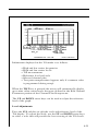
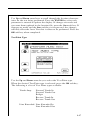
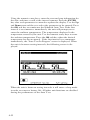
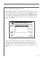
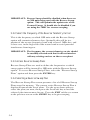
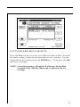
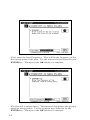
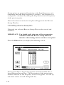
How To Make FCC In-Channel Response Measurements
(FCC limit: , + 2 dB)
The frequency response of any channel can be measured using the
spectrum analyzer mode. A flat signal source must be inserted at the
input of the modulator or processor. In testing a modulator this
source may be a full field multiburst signal, or a sweeping function
generator. For a processor, a bench sweep generator or a broadband
noise source may be used. The response is monitored with the
Stealth receiver in the spectrum analyzer mode. A 5 or 10 MHz span
may be used. The “Max Hold” function is used to ensure that the
peak levels are measured at all frequencies. The scale may be set to
as low as 0.5 dB/div, but the operator will use the appropriate scale
setting to enable display of the full response on screen. The operator
then positions the markers at the maximum and minimum points of
the display and reads the “delta” indicated at the bottom of the
screen. The FCC requirement is a window of ±2.0 dB, which means
the delta should be < 4 dB.
How To Make CSO/CTB Measurements
CSO (Composite Second Order) is a clustering of second order beats
at any frequency in the spectrum, which causes interference to
picture quality when they fall within the video bandwidth. CTB
(Composite Triple Beat) is a clustering of third order distortion
products usually around the video carrier frequency.
The ability to make these measurements allows the technician to
troubleshoot and correct the cause of this unwanted distortion.
NOTE: It is recommended that a < 12 MHz band pass filter be used
to limit the amount of intermodulation distortion caused by
overload of the RF input of the receiver. If a preamplifier is
used, it should be placed between the bandpass filter and the
receiver.
Press the CSO/CTB soft key to initiate CSO/CTB measurements.
The unit will first switch to a 30 kHz resolution bandwidth, measure
the carrier and then prompt you to turn the carrier off.
4-36