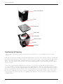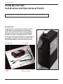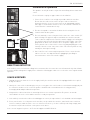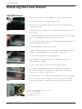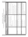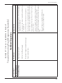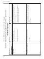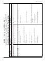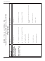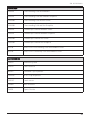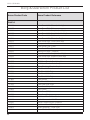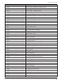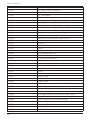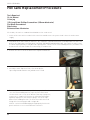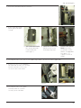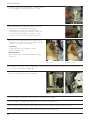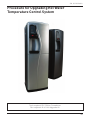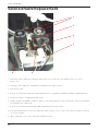
1
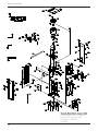
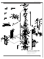
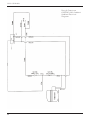
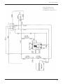
INSTALLATION &
OPERATION GUIDE
628 & 698 MODELS
Technical
Manual
628 & 698 Models
Contents
Range Overview . . . . . . . . . . . . . . . . . . . . . . . . . . . . . . . . . . . . . . . . Page 4
Installation & Operation Guides (inc Accessories). . . . . . . . . . . . . Page 8
Sanitisation and Descaling Guides . . . . . . . . . . . . . . . . . . . . . . . . Page 20
Trouble Shooting Guides . . . . . . . . . . . . . . . . . . . . . . . . . . . . . . . . Page 24
Exploded Diagrams . . . . . . . . . . . . . . . . . . . . . . . . . . . . . . . . . . . . Page 36
Parts Listing . . . . . . . . . . . . . . . . . . . . . . . . . . . . . . . . . . . . . . . . . . Page 43
Machines & Accessories Listing . . . . . . . . . . . . . . . . . . . . . . . . . . Page 46
Product Listing . . . . . . . . . . . . . . . . . . . . . . . . . . . . . . . . . . . . . . . . Page 48
Categorised Parts Ordering Guide and Returns Note . . . . . . . . . Page 56
Step-By-Step Guides . . . . . . . . . . . . . . . . . . . . . . . . . . . . . . . . . . . Page 59
Technical Manual
Section1
628 & 698 Models
Range Overview
A comprehensive range of watercoolers, available in two different operational types:
• “Classic”- Reservoir Model
(Cold Water Storage Tank)
• “Direct Chill” Model
(No Stored Drinking Water)
Both types are available as:
• Floorstanding
• Countertop
All Reservoir models are available as either
• Cold and Ambient
• Hot and Cold
Direct Chill models are currently only available as Cold and Ambient.
4
628 & 698 Models
All types
All b & o “Classic” & “Direct Chill” models are self contained machines with robust steel sided cabinets and
attractively moulded front and top panels.
An IEC Power Lead is supplied for connection to the IEC socket found on the rear of all models.
Floorstanding Models
All are supplied with an opening lower door and are prefitted with a removable filter mounting bracket. A water
inlet fitting is provided to the bottom right hand corner.
(Adjustable feet will be standard from 2009).
Countertop Models
A void is provided with the front panel area to accommodate most filter types where external installation in an under
cabinet is not possible.
“Classic” Reservoir Model:
Water is fed into the reservoir via the Float Valve mounted in the Tank Lid. The Float Valve controls the water level in
the tank. Ensure a Pressure Reducing Valve is fitted to all supplies greater than 3.5 bar pressure.
The Baffle Plate inside the Cold Tank maintains separation between the lower chilled water and upper ambient
water. (The cooling system only chills water in the lower part of the Cold Tank).
Dispense is at gravity pressure only via push operated Taps.
The Cold Temperature is thermostatically controlled via the adjustment screw on the back of the machine. This is
factory set and is not necessary to adjust in most cases. (See Controls)
On Hot & Cold versions, the Hot Tank is fed with ambient temperature water from the upper area of the Cold Tank.
The Hot Temperature is thermostatically controlled with sensors on the outside of the Hot Tank. These are preset
and are not adjustable. The system is designed so that the Hot Tank is impossible to run dry under normal usage.
Running dry can only occur if the inlet water is drained using the Drainage Point provided. In the event of running
dry the Overheat sensor would switch off the heater until manually reset.
5
628 & 698 Models
Controls
Cold & Ambient Models
Electrical On/Of switch - At upper rear of machine. Switches on Cooling Operation.
Cold Thermostat - At rear of machine. On Classic models and inside the machine, next to the Chill Tank, on DC
Models.
Factory set to:
+C
-C
NB: Turn clockwise to decrease water temperature
Ambient Tap
Press downwards to dispense Ambient water
Cold Tap
Press downwards to dispense Cold Water
Green LED (Top)
Colours to show Cooling Operation is switched on
Yellow LED (Bottom)
Colours to show when compressor is operating
Hot & Cold Machines:
Electrical On/Off Switches
At upper rear of machine
Cold - Switches on Cooling Operation
Hot - Switches on Heating Operation
10A Fuse
At upper rear of machine
Hot Tap
Lift Safety Tag and press downwards to dispense Hot Water
Cold Tap
Press downwards to dispense Cold Water
Green LED (Top)
Colours to show Cooling Operation is switched on
Yellow LED (Middle)
Shows when heating mode is switched on
Red LED (Bottom)
Colours to show when main heater is operating (i.e. Off when water is at
temperature)
Hot Tank Overheat Reset Button
On sensor on side of Hot Tank (Press to operate if required. Ensure
electrical power is disconnected before doing so).
6
Technical Manual
Section 2
628 & 698 Models
CW698
Installation and Operational Guide
IMPORTANT - the guide must be read before attempting to connect the machine.
Introduction
Congratulations on your wise choice of water cooler. Your Borg & Overström water cooler will provide you with a
continuous supply of water 24 hours a day. To ensure that his product will always perform as it truly should, the
user should initially read this manual thoroughly and follow all the instructions before operation of the unit
commences.
Installation
The water connection to the Borg & Overström water cooler is via a 1/4” supply. The connection can either be made
utilising the bulk head connector found at the rear of the machine or by connecting an in-line straight connector
direct to the pipe inside the rear of the machine. It is advisable that in any case an in-line isolation tap should be
installed on the supply just behind the machine in case of emergency.
Operation Method
1. Having connected the water supply to the rear of the machine, the water supply should be turned on and you will
hear the reservoir within the machine start to fill. Once this has stopped filling, the entire tank should then be
drained and allowed to refill before operation of the machine commences. If in any doubt at this stage please add
some sanitisation fluid to your initial tank of water so as to flush the machine before use. Once the machine has
refilled with water the machine can be connected to the mains supply and switched on.The switch at the rear of the
machine then needs to be turned on before operation can commence.
NB. If your water cooler has a hot water facility please allow time for the hot tank to fill up before turning on. To
draw water into the hot tank, the hot tap must be held open until water starts to dispense.
2. Both LEDs on the display panel should now be showing. After initial chilling operation has been completed the
chilling lens will go off, which is the bottom of the two lenses showing.
Machine Positioning
1. It is important that at least 10cm is left between the back of the machine and the surface against which it is
placed. This is to ensure that the machine does not in any way overheat.
2. The machine must be kept away from any direct sunlight.
3. It is important that the machine is connected to an RCD connected supply making doubly sure that the voltage
supply is compatible with the machine.
8
628 & 698 Models
Top cover
Baffle plate
Float valve
Indicator panel
Taps
Drip Tray
Hot & cold switches
Inlet
Sanitisation & Cleaning
1. Please make sure that the machine has been disconnected from the electrical supply before any cleaning
commences.
2. The lid of the machine should be removed exposing the inside of the water tank. Now press both the cold tap and
the ambient tap to drain all the water from the reservoir until no water can be seen. Remove the baffle plate found
in the centre of the tank passing it around the float valve to remove it completely. At this stage it is possible to see
whether any water has been left in the base of the tank. A hundred miliilitres of sanitising fluid can now be tipped
into the reservoir.
3. The water can be turned on again briefly to half fill the reservoir with sanitising fluid. The upper half of the
reservoir should be cleaned utilising sanitisation wipes supplied by Azure. Whilst the sanitisation fluid is having its
effect, please clean the external casing with Azure sanitisation wipes. Once the sanitisation fluid has been left for a
satisfactory period of time, please flush the water cooler through at least once by turning the water back on. When
this has been completed, the machine can be reassembled and your sanitisation is complete. Please now switch
the power back on. If you have any question regarding sanitisation please do not hesitate to ring Azure Head Office
on 0845 4 50 30 90.
9
628 & 698 Models
DC698
Installation and Operational Guide
IMPORTANT - the guide must be read before attempting to connect the machine.
Introduction
Congratulations on your wise choice of water cooler. Your Borg & Overström water cooler will provide you with a
continuous supply of water 24 hours a day. To ensure that his product will always perform as it truly should, the
user should initially read this manual thoroughly and follow all the instructions before operation of the unit
commences.
Installation
The water connection to the Borg & Overström water cooler is via a 1/4” supply. The connection can either be made
utilising the bulk head connector found at the rear of the machine or by connecting an in-line straight connector
direct to the pipe inside the rear of the machine. It is advisable that in any case an in-line isolation tap should be
installed on the supply just behind the machine in case of emergency.
Operation Method
1. Having connected the water supply to the rear of the machine, the water supply should be turned on and you will
hear the header tank and ice bank starting to fill. Once this has stopped filling, the machine can be connected to the
mains supply and switched on. The switch at the rear of the machine then needs to be turned on before operation
can commence.
NB. If your water cooler has a hot water facility please allow time for the hot tank to fill up before turning on. To
draw water into the hot tank, the hot tap must be held open until water starts to dispense.
2. Both LEDs on the display panel should now be showing. After initial chilling operation has been completed the
chilling lens will go off, which is the bottom of the two lenses showing.
Machine Positioning
1. It is important that at least 10cm is left between the back of the machine and the surface against which it is
placed. This is to ensure that the machine does not in any way overheat.
2. The machine must be kept away from any direct sunlight.
3. It is important that the machine is connected to an RCD connected supply making doubly sure that the voltage
supply is compatible with the machine.
10
628 & 698 Models
Top cover
Cover of Header
Tank
Ice Bank
Header Tank
Float Valve
Indicator Panel
Cold Water Button
Hot Water Button
Drip Tray
Hot & cold switches
Inlet
Sanitisation & Cleaning
1. To commence sanitisation, simply isolate the water supoply and remove the filter cartridge.
2. Having removed the filter cartridge you now connect the dosing cartridge supplied by Azure with 125ml of
sanitisation fluid inside.
3. Now simply hold on the cold and ambient water button until the sanitisation until the sanitisation fluid hsa been
flushed through the system.
4. The last stage is to fully clean the external casing with Azure sanitisation wipes. When this has been completed
your sanitisation is complete.
If you have any question regarding sanitisation please do not hesitate to ring Azure Head Office on
0845 4 50 30 90.
11
628 & 698 Models
CW628
Installation and Operational Guide
IMPORTANT - the guide must be read before attempting to connect the machine.
Introduction
Congratulations on your wise choice of water cooler. Your Borg & Overström water cooler will provide you with a
continuous supply of water 24 hours a day. To ensure that his product will always perform as it truly should, the
user should initially read this manual thoroughly and follow all the instructions before operation of the unit
commences.
Installation
The water connection to the Borg & Overström water cooler is via a 1/4” supply. The connection can either be made
utilising the bulk head connector found at the rear of the machine or by connecting an in-line straight connector
direct to the pipe inside the rear of the machine. It is advisable that in any case an in-line isolation tap should be
installed on the supply just behind the machine in case of emergency.
Operation Method
1. Having connected the water supply to the rear of the machine, the water supply should be turned on and you will
hear the reservoir within the machine start to fill. Once this has stopped filling, the entire tank should then be
drained and allowed to refill before operation of the machine commences. If in any doubt at this stage please add
some sanitisation fluid to your initial tank of water so as to flush the machine before use. Once the machine has
refilled with water the machine can be connected to the mains supply and switched on.The switch at the rear of the
machine then needs to be turned on before operation can commence.
NB. If your water cooler has a hot water facility please allow time for the hot tank to fill up before turning on. To
draw water into the hot tank, the hot tap must be held open until water starts to dispense.
2. Both LEDs on the display panel should now be showing. After initial chilling operation has been completed the
chilling lens will go off, which is the bottom of the two lenses showing.
Machine Positioning
1. It is important that at least 10cm is left between the back of the machine and the surface against which it is
placed. This is to ensure that the machine does not in any way overheat.
2. The machine must be kept away from any direct sunlight.
3. It is important that the machine is connected to an RCD connected supply making doubly sure that the voltage
supply is compatible with the machine.
12
628 & 698 Models
Hot & cold switches
Inlet
Top Cover
Baffle Pipe
Float Valve
Indicator Panel
Taps
Drip Tray
Sanitisation & Cleaning
1. Please make sure that the machine has been disconnected from the electrical supply before any cleaning
commences.
2. The lid of the machine should be removed exposing the inside of the water tank. Now press both the cold tap and
the ambient tap to drain all the water from the reservoir until no water can be seen. Remove the baffle plate found
in the centre of the tank passing it around the float valve to remove it completely. At this stage it is possible to see
whether any water has been left in the base of the tank. A hundred miliilitres of sanitising fluid can now be tipped
into the reservoir.
3. The water can be turned on again briefly to half fill the reservoir with sanitising fluid. The upper half of the
reservoir should be cleaned utilising sanitisation wipes supplied by Azure. Whilst the sanitisation fluid is having its
effect, please clean the external casing with Azure sanitisation wipes. Once the sanitisation fluid has been left for a
satisfactory period of time, please flush the water cooler through at least once by turning the water back on. When
this has been completed, the machine can be reassembled and your sanitisation is complete. Please now switch
the power back on. If you have any question regarding sanitisation please do not hesitate to ring Azure Head Office
on 0845 4 50 30 90.
13
628 & 698 Models
Cup Dispenser
1. Carefully unpack and inspect for damage.
2. Select fitting position (Normally at top of right hand side panel towards front of machine).
3. Attach self adhesive pad to mounting bracket and affix to chosen site
(Clean area first to ensure good adhesion).
4. Additionally, self tapping screws can also be used to ensure a secure fitting.
14
628 & 698 Models
LEAK DETECTOR
Installation and Operational Guide
IMPORTANT - the guide must be read before attempting to connect the machine.
Introduction
Congratulations, you have chosen wisely to add a
Leak Detector to your Borg & Overström water
cooler. This product does not in anyway provide a
guarantee or insurance against any flooding but
provides the means of added prevention. Please
ensure that you read this manual thoroughly before
proceeding, and take note of the installation and
operation procedures to achieve the best results.
Inlet and Outlet
Probes
15
Re-set switch
Connection plugs
628 & 698 Models
Installation & Operation
This product can only be used in conjunction with a Borg & Overström water
cooler.
Please follow the step-by-step procedures for installation:
1. Please fix the Leak Detector as high as possible within the machine.
Ensure that the red lever has sufficient space to be activated. It is
imperative that the electrical connections are facing upwards and the
water pipe is installed into the base of the Leak Controller and that the
Leak Controller is mounted vertically.
2. The detection probes can now be fixed into their locating holes in the
channel within the base plate.
3. The inlet and outlet connection ports for the water are connected via 1/4”
push fit fittings. The pipe already located within the machine must be
connected to the outport on the machine and the supply feed coming into
the machine must therefore be placed into the inport. Find a connection
plug within the back of the machine where the power supply comes in.
Please part the two sections of this connection plug and plug your Leak
Controller into these two connections. Note: This will only work one way
round (you cannot get it wrong).
4. Your Leak Detector is now ready for operation. Please ensure that the
red lever is in the closed position before plugging in your Borg &
Overström water cooler to the mains supply.
RESETTING DETECTOR
In the unlikely event of a leak from a Borg & Overström machine the water detector will automatically shut off both
the power and incoming water supply. Please follow the following procedures to reset the detector to regain normal
operation.
LEAKS & REPAIRS
1. Unplug the machine from the electrical supply. Intially the machine must be left unplugged whilst the repair is
being carried out.
2. Identify the cause of the leak and replace any necessary parts. Once this has been carried out thoroughly dry out
the channel in the base of the cooler. The probes should then be removed from their locating positions,
thoroughly dried and placed back into position.
3. Now push the red lever back into its normal position so as to return to operation. The power can now be
switched back on to the cooler and the machine is ready for operation.
4. In the unlikely event that the red lever should trigger once more, then procedures 1 to 3 should be carried out again.
5. Please note that the electical power to the machine, not just within the machine, must be disconnected for at
least 5 seconds to enable the device to reset. A shorter on-off-on cycle time is unlikely to be long enough, and
the machine on/off switch will not cut the power to the device.
In the event of any queries please call Technical Support on 0845 4 50 30 90.
16
628 & 698 Models
Installing the Level Sensor
698/698H Models:
Fig.1
Fig.2
1.
Ensure water and electricity supplies to machine are switched off.
2.
Remove Tap Cover Panel and disconnect PCB
3.
Remove Front Panel. (Be ready to catch Lower Door when lifting
Front Panel Clear)
4.
Carefully remove screws from rear condenser panel and gently ease
panel away.
5.
Fit short drainage tube to drainage outlet on rear on Front Panel (with
any curve running up in centre as shown in picture 1)
6.
Refit Front Panel (and Lower Door) routing drainage tubing under Hot
Tank towards back of machine.
7.
Fit Drainage Elbow fitting (see picture 2)
8.
Position Elbow through hole in shelf (picture 3) and hold in position by
fitting second drainage tube from underside (see picture 4)
9.
Position Drainage Tank in lower compartment
10. Fit Control Unit to inside wall of lower compartment with selfadhesive pad as supplied
Fig.3
11. Connect small wiring to Float Switch assembly on tank
12. Disconnect main wiring terminal block (See picture 5) and insert
Control Unit wiring. (The terminals are individually configured to
ensure correct order of connection).
13. Carefully refit the rear condenser panel and turn on the inlet supplies
Fig.4
14. The Level Sensor is now ready for use. The Control unit will bleep
when the tank requires emptying after which it will automatically
reset.
For further help and advice, please contact:
Azure Technical Support
Tel: ++ (0) 1362 656926
[email protected]
Fig.5
17
628 & 698 Models
The Waste Kit
• Remove Filter Bracket from base of machine and place container inside
• Remove top lid. This will allow access to the rear of the drip tray area.
• Connect the 2 lengths of silicone tube together using the 90 degree elbow
• Connect the shorter length to stem on the rear of the drip tray area.
• Feed the tube to the back of the machine where it can be directed into the base.
Connect to the lid of the container.
• Remove the bung from the stem of the drip tray and the machine can now be put into service.
18
Technical Manual
Section 3
628 & 698 Models
Sanitisation Guide
Direct Chill Water Coolers
Turn off incoming mains water, briefly press dispense button(s) to release internal water pressure from the
machine and remove filter. If possible temporarily shut off inlet to any hot tank as sanitisation of a hot tank in
continuous use is unnecessary.
Add 100 ml of a proprietary sanitisation fluid to a clean and empty service filter cartridge/dosing device and connect
into machine. Always ensure to use a reputable branded sanitisation fluid for effective action.
Please note: We recommend using a 3% Hydrogen Peroxide concentration base sanitising fluid of reputable
manufacture to the appropriate dilution ratios as supplied with the product or typically 1:30 max. (Stronger
concentrations will require larger dilution rates).
Please remember that most sanitisation fluids (including ozone) contain an active caustic/alkaline agent. Always
use responsibly and with care remembering that due to its alkaline nature unnecessary concentrated/prolonged
contact with any materials, including metals, can cause damage. Always rinse all contact surfaces after use with
clean water.
Turn on incoming water, allow service cartridge/doser to fill and then draw off at least 1 litre of water for the
machine to ingest the solution. Leave solution for 10 minutes inside machine for sanitisation to take effect. During
this time thoroughly clean the machine externally. For this we recommend the use of proprietary disposable
sanitisation wipes. Pay particular attention to the dispense faucet and the push button controls. Remember to
include the drip tray. If a Waste Overflow System is fitted, this may benefit from flushing through with a small
amount of dilute sanitisation fluid. Optionally you may replace the dispense faucet and/or descale it.
After a satisfactory period of time, flush the machine with at least 10 litres of clean water to clear any trace of the
sanitisation fluid. Optionally use test strips to check.
Turn off water and remove the service filter/doser and fit a new filter of reputable quality and suited to the site
conditions. We recommend pre-flushing the new filter to reduce any risk of any loose media in the filter entering
the solenoid valves and possibly causing a malfunction. Retain the service cartridge/doser for reuse.
Turn on incoming water supply and carefully ensure the thorough sanitising of the outside of the machine is
completed. Reconnect power and reset any service/filter life monitors accordingly. Ensure any hot tank inlet is
reconnected and the tank is purged of air before switching heater on again.
ALWAYS ENSURE ANY RESIDUAL AIR HAS BEEN PURGED FROM BOTH
COLD AND HOT SYSTEMS AND ALL IS OPERATIONAL BEFORE LEAVING.
20
628 & 698 Models
Sanitisation Guide
Reservoir Water Coolers
Please make sure that the machine has both been switched off and disconnected from the electrical supply and
that the water is turned off, use the taps (and drain point if fitted) to drain off all the water, before any cleaning
commences.
The lid of both the machine and the tank should be removed exposing the inside of the water tank. Remove the
baffle plate found in the centre of the tank. Any lime scale or mineral deposits should first be removed by manual
scrubbing with a non-metallic sponge-scouring pad. For stubborn deposits, most domestic brand stainless steel
cleaners can also be used.
If your machine is a Hot & Cold machine please ensure that the inlet to the hot tank is closed off sufficiently to
prevent sanitisation fluid entering the hot system.
If using a service dosing cartridge, please now go straight to no 4. At this stage it is possible to see whether any
water has been left in the base of the tank, 100ml of sanitising fluid can now be tipped into the reservoir. (We
recommend a hydrogen peroxide base sanitising fluid of reputable manufacture using the dilution ratios as
supplied with the product.)
Remove the existing filter and install a filter head to suit the service cartridge if necessary. Empty 100ml of
sanitisation fluid into the service cartridge and connect the cartridge to the filter head.
The water can be turned on again briefly to half fill the reservoir, forming a sanitising solution. The upper half of the
reservoir should be cleaned with sanitisation wipes. Leave for 10 minutes to effect sanitisation, whilst the
sanitisation solution is having its effect, please fully clean the external casing with sanitisation wipes, ensuring
particular attention is paid to the faucets. Once the sanitisation fluid has been left for a satisfactory period of time
please flush the water cooler through at least once with clean water.
When this has been completed, the machine can be reassembled and your sanitisation is complete. Always
remember to replace the filter(s) with the appropriate type(s). (Retain service/dosing cartridges for reuse.) Please
now switch the power back on.
Ozonation is another alternative, but not a recommended method, as we believe the opportunity should always be
taken to inspect the machine internally, remove any scale or mineral build-ups and take interventive action where
appropriate.
ALWAYS PURGE AIR FROM THE COLD AND HOT SYSTEM BEFORE
SWITCHING POWER ON AGAIN.
21
628 & 698 Models
Descaling Guide
Reservoir Model
Scale deposits will occur whenever water is heated. Higher deposits will occur with harder water and higher
temperatures. Although scale deposits can be reduced through using softened water this is not necessarily
desirable due to the adverse effect on taste. Therefore, it is important that descaling is carried out regularly to
maintain the high efficiency of operation of your appliance.
The frequency of descaling depends on the hardness of the water and the intensity of usage in each case. At least
every 12 months is highly recommended. Although it is primarily the Hot Tank (Water Heater) that requires
descaling, it is also necessary to sometimes carry out some in the cold tank.
Please note: Descaling is to remove the inevitable build up of limescale and should not be
confused with sanitisation, which is a different procedure for maintaining the necessary
hygiene standards for drinking water.
1. Switch off the power and water supply. Drain off water, including Hot Tank. It may be beneficial at this stage to
flush through the hot tank with clean water to remove as much loose scale as possible if the tank appears
particularly scaled up.
2. Carefully fill a suitable pouring jug with approx 2 ½ litres of hot water and add the correct amount of descaler
relevant to the enclosed instructions for safe and effective use.
3. Remove the Top Cover from the appliance (and the lid covering the cold tank on later models).
Carefully remove the Float Valve and Baffle Plate from the Cold Tank.
4. Slowly pour the descaling solution into the Cold Tank. This will drain directly into the Hot Tank. Continue to add
the solution until it also just begins to fill the Cold Tank too. Leave the solution to react with the limescale as
directed.
5. Should limescale be present in Cold Tank, carefully treat the areas concerned using the same solution. Also,
treat any removed parts such as the Float Valve, after checking the directions for use for compatibility. Similarly,
if the outlet taps need treatment, dispense a little solution to draw it into the taps. Examine the small black
rubber water stop seal on the Float Valve for any damage or wear and replace if necessary. DO NOT ROTATE
THE SEAL IF IT IS NOT BEING REPLACED AS THIS COULD AFFECT ITS WATER SEAL SEATING AND ALLOW
SEEPAGE.
6. After an appropriate time, carefully scrub any surface scale to remove it taking care not to damage the part. If
scrubbing of the inside of the taps is required, remove the Front Panel of the appliance and carefully dismantle
the taps by unscrewing the ring under the lever and then drawing the lever mechanism upwards out of the body.
N.B. Before removing the taps, drain off any remaining solution in the cold tank.
7. Reassemble any removed parts as necessary and flush appliance through thoroughly with mains water as
directed (Carry out sanitisation procedure at this point if desired).
8. Finally, allow appliance to refill, check for any leaks and switch on power supply.
22
Technical Manual
Section 4
24
From Hot Tap
From Cold Tap
Ambient Water too warm
No Water Dispenses
Problem/ Report
M O D E L S
Carry out checks and actions as for ambient tap.
Thaw out and increase Cold Water temperature set
point.
Thaw out and check and replace Cold Thermostat
Firstly all as for Ambient Tap
Cold area of tank frozen - Thermostat set too low
Cold area of tank frozen – Faulty Thermostat
Replace Tank
Check and unblock/replace as needed
Blocked Tank outlets/pipes
Tank very heavily scaled up
Replace/adjust position/repair as needed
Reservoir Float Valve jammed up (and Tank empty)
Unblock/replace Hot Water Pipe and Hot Vent Pipe
(Check water level showing in Hot Vent Pipe)
Check Tap action. Dismantle Tap and replace
complete or just washer, as needed.
Faulty Tap (and tank full)
Airlock in dispense pipe work
Turn off elec and water and reset (Check for leaks)
“Leak detector” (if fitted) tripped off (and Tank
Empty)
Carry out checks and actions as for ambient tap.
Reset “Waterblock” (and check for any leaks)
“Waterblock” tripped off (and Tank empty)
Firstly all as for Ambient Tap
Check all Taps/valves/ filters on incoming supply are
fitted and are turned on.
Suggested Action
Water Supply turned off (and Tank empty)
Possible Cause
No Water Dispenses
Trouble Shooting Fault Diagnosis Guide (1)
R E S E R V O I R
628 & 698 Models
Possible Cause
Cold water not Cold
Ambient Water too warm
Decrease Cold Thermostat set point
Replace Thermostat
Replace Thermostat
Contact Azure Technical Support
Contact Azure Technical Support
Check power cord connected and live, and machine
is switched on.
Replace thermostat
Check and replace relays
Check and refit relays
Contact Azure Technical Support
Refit Baffle Plate
Faulty Thermostat
Compressor runs but not Switching off (Hot to
touch)
Refrigeration problem
Compressor not running at all
No elec power supply
Thermostat faulty
Compressor only hums slightly/ briefly
Relays loose
Compressor Faulty
Cold Tank Baffle Plate Not Connected
Advise customer
High usage and fed from water supply pipe in
warm ducting
Compressor runs and switching off (cool/warm to
touch) - Thermostat set too high
Check Tank Insulation fitted and / or advise
customer
Suggested Action
Low usage and heat from compressor influencing
stored water
Water Dispenses But Not Correct Temperature
Problem/ Report
Water Dispenses but Not Correct Temperature
Trouble Shooting Fault Diagnosis Guide (2)
628 & 698 Models
25
26
Warm Temperature - not hot
Ambient Temp only
Hot Water Not Hot
Problem/ Report
Reset Overheat Button on Hot Tank
Locate break and repair
Check supply voltage and current to Heater Band
and replace accordingly
Check supply voltage and current to Hot Thermostat
and replace accordingly
Carry out thorough descale/ complete replacement
of Hot Tank
Heating operation tripped off (No Yellow LED)
Break in supply wiring to control circuit
Main reheat element not working (Red LED on all
the time)
Hot tank heavily scaled up (signs of scale in top of
Cold Tank, loud boiling noises etc)
Break in supply wiring to main element
Locate and repair break
Switch on
Suggested Action
Heating operation switched off (No Yellow LED)
Possible Cause
Water Not Hot
Trouble Shooting Fault Diagnosis Guide (3)
628 & 698 Models
Locate and repair accordingly
Locate and repair accordingly
Leak in supply inlet pipe-work and / or filter
Leak from machine hose or tubing
Water lying in bottom of
machine or on mid shelf
Check pressure and fit pressure reducing valve if
needed
Check and repair float valve
Replace washer
Replace Hot Tank
Check and replace Probe (Conversion Kit
recommended)
Check and replace Main Control Board (Conversion
Kit recommended)
Check insulation and repair/replace accordingly
Water pressure too high
Jammed Float Valve
Split Float Valve Washer
Overflowing Cold Tank (Hot Tank exclusively
sealed)
Hot Tank thermistor probe faulty (Pre 0708 models
only)
Control Board Failure (Pre 0708 models only)
Condensation from tank or Cold Water Pipe
Overflowing Cold Tank
Empty Drip Tray
Suggested Action
Overflowing Drip Tray
Possible Cause
Water lying on top edge of
lower door panel and / or
bottom of machine
Water Leaks
Problem/ Report
Water Leaks
Trouble Shooting Fault Diagnosis Guide (4)
628 & 698 Models
27
28
Tripping out Electricity
supply
(Contact Azure Technical Support for further advice)
Test, identify and address accordingly.
Electrical circuitry faults
Replace missing fittings
Missing Fittings
Discuss possible repositioning with customer
Level up machine (Adjustable feet from early 2009)
Uneven Surface
Machine in high humidity environment
No action needed. This is quite normal.
Level Surface
Compressor Starting
Replace PCB
Faulty PCB (Machine working normally otherwise)
Machine shakes on Start-Up
Check power supply and reconnect as necessary
(Also check out other symptoms as described
separately)
No electricity to Machin
No LED Lights
Empty Level Sensor Tank
Suggested Action
Level Sensor fitted and Tank full
Possible Cause
Bleeping Noise
Miscellaneous
Problem/ Report
Trouble Shooting Fault Diagnosis Guide (5)
Miscellaneous
628 & 698 Models
From Ambient Valve
No Water Dispenses
Problem/ Report
C H I L L
M O D E L S
O N L Y
Check power cord connected and live and machine
is switched on.
Reset “Waterblock” (and check for any leaks)
Check valve action. Carefully dismantle valve and
clean out/part replace/complete replace as needed.
No Electricity/Power Supply
“Waterblock” tripped off (and Tank empty)
Faulty Solenoid Valve
If present, replace solenoid coil/whole valve
coil/whole valve assembly complete.
Valve not clicking-Check whether voltage is present
when operated (Caution-High Voltage). If not
present check wiring for continuity and /or replace
PCB.
Valve clicking but no water-Check if hole in centre of
washer is clear.
Check all Taps/valves/ filters on incoming supply are
fitted and are turned on.
Suggested Action
Water Supply turned off
Possible Cause
No Water Dispenses
Trouble Shooting Fault Diagnosis Guide (6)
D I R E C T
628 & 698 Models
29
30
From Ambient or Cold Valve
From Cold Tap
No Water Dispenses
Problem/ Report
C H I L L
M O D E L S
O N L Y
Thaw out and check and replace Air pump and or
check electricity supply to pump present
Chiller tank Frozen-faulty air pump
Faulty PCB
Replace PCB
Press button firmly. N.B. This could be caused by a
surrounding cold environment making the action
stiffer
Thaw out and check and replace Cold Water
temperature set point.
Chiller tank frozen - Faulty Thermostat
Button Not being pressed enough
Carry out checks and actions as for ambient tap.
Suggested Action
Firstly all as for Ambient Tap
Possible Cause
No Water Dispenses
Trouble Shooting Fault Diagnosis Guide (6) continued
D I R E C T
628 & 698 Models
M O D E L S
O N L Y
Possible Cause
• Faulty Thermostat
Check power cord connected and live, and machine
is switched on.
Check and replace relays
Check and refit relays
Contact Azure Technical Support
No elec power supply
• Compressor only hums slightly/ briefly
• Relays loose
• Compressor Faulty
Compressor not running at all
• Refrigeration problem
Contact Azure Technical Support
Replace Thermostat
Compressor runs and switching off (cool/warm to
touch) - Thermostat set too high
Cold water not Cold
Compressor runs but not Switching off (Hot to
touch)
Decrease Cold Thermostat set point
Low usage and / or fed from water supply pipe in
warm ducting
Ambient Water too warm
Advise customer
Suggested Action
Water Dispenses but Not Correct Temperature
Water Dispenses but Not Correct Temperature
Problem/ Report
C H I L L
Trouble Shooting Fault Diagnosis Guide (7)
D I R E C T
628 & 698 Models
31
32
M O D E L S
O N L Y
• Split Float Valve Washer
• Jammed Float Valve
• Water pressure too high
Replace washer
Check and repair float valve
Check pressure and fit pressure reducing valve if
needed
Locate and repair accordingly
Leak from machine water pipework fittings
Overflowing Header Tank
Locate and repair accordingly
Leak in supply inlet pipe-work and / or filter
Water lying in bottom of
machine or on mid shelf
Empty Drip Tray
Suggested Action
Overflowing Drip Tray
Possible Cause
Water Leaks
Water lying on top edge of
lower door panel and / or
bottom of machine.
Water Leaks
Problem/ Report
C H I L L
Trouble Shooting Fault Diagnosis Guide (8)
D I R E C T
628 & 698 Models
M O D E L S
O N L Y
Tripping out Electricity
supply
(Contact Azure Technical Support for further advice)
Test, identify and address accordingly.
Electrical circuitry faults
Replace missing fittings
Missing Fittings
Discuss possible repositioning with customer
Level up machine (Adjustable feet from early 2009)
Uneven Surface
Machine in high humidity environment
No action needed. This is quite normal.
Level Surface
Compressor Starting
Replace PCB
Faulty PCB (Machine working normally otherwise)
Machine shakes on Start-Up
Check power supply and reconnect as necessary
(Also check out other symptoms as described
separately)
No electricity to Machin
No LED Lights
Empty Level Sensor Tank
Suggested Action
Level Sensor fitted and Tank full
Possible Cause
Miscellaneous
Bleeping Noise
Miscellaneous
Problem/ Report
C H I L L
Trouble Shooting Fault Diagnosis Guide (9)
D I R E C T
628 & 698 Models
33
34
M O D E L S
O N L Y
Possible Cause
From Ambient or Cold Water
Valve
Continuous Water Dispense
From Ambient or Cold Water
Valve and hammering noise
From Ambient or Cold Water
Valve
Intermittent Water Dispense
From Ambient or Cold Water
Valve
Press button firmly N.B. This could be caused by a
surrounding cold environment making the action
stiffer
Faulty PCB
Replace PCB and or/ button Panel as needed
Dismantle Valve and clean out
Debris blocking hole in diaphragm window
Contact Azure Technical Support regarding special
replacement washers available
Button jammed on/faulty
Fluctuating mains water pressure situation
Pre flush filters
Button Not being pressed enough
Replace PCB
Hold button on to purge air out. (This could take
several minutes where pressure is low)
Fit Booster Pump Set
Consider replumbing to alternative supply if
possible
Trapped air in pipe work (especially where water
pressure is low or after filter change)
Low incoming Water pressure
Suggested Action
Intermittent Water Dispense/Continuous Water Dispense
Slow but Continuous Water Dispense
Problem/ Report
C H I L L
Trouble Shooting Fault Diagnosis Guide (10)
D I R E C T
628 & 698 Models
Technical Manual
Section5
628 & 698 Models
Borg & Overstrom Classic 628
Cold & Ambient/Countertop
Exploded Component View
Production no 628-10
Jan 2009
36
628 & 698 Models
Borg & Overstrom Classic 628H
Hot & Cold/Countertop
Exploded Component View
Production no 628-10H
Jan 2009
37
628 & 698 Models
Borg & Overstrom Classic 698
Cold & Ambient/Floorstanding
Exploded Component View
Production no 698-10
Jan 2009
38
628 & 698 Models
Borg & Overstrom Classic 698H
Hot & Cold/Floorstanding
Exploded Component View
Production no 698H-10
Jan 2009
39
628 & 698 Models
Borg & Overstrom
628/698 Cold & Ambient
Ambient Electrical
Diagram
40
628 & 698 Models
Borg & Overstrom
628/698 Hot & Cold
Production series No 10
41
Technical Manual
Section6
628 & 698 Models
Azure Part No.
123817
123826
123815
123826
120915
120225
120916
120926
120915
120224
125821
125811
126824
126825
124951
124251
142165
142265
143281
142365
143282
144071
131574
131573
131572
121859
133411
133412
127842
127841
121955
121956
121255
121526
122825
122835
122945
122245
174318
174319
174316
134602
184623
184624
131642
184626
184628
131422
133413
131575
131643
131644
171203
171202
171201
171204
173251
174321
174315
174313
172152
172154
172156
172158
172153
172159
172161
172162
172157
43
Azure Ref
Inner Top Panel-Silver
Inner Top Panel-Graphite
Outer Top Panel-Silver
Outer Top Panel-Graphite
Front Panel Silver
Front Panel-Graphite
Door Panel-Silver
Door Panel-Graphite
Drainage Hose Elbow
Front Panel Silver(No Drip)
Front Panel Graphite(No Drip)
Drip Tray Set -Graphite
Drip Tray Set -Silver
Tap Cover Panel-Graphite
Tap Cover Panel-DC
698 Base Panel
628 Base Panel
Cold Tap
Ambient Tap
Ambient Water tap tag
Hot Tap(with Safety Tag)
Hot Tap Safety Tag
Tap BackNut
Condenser Panel Spacer
Drip Tray O-Ring
Drip Tray Bung
Side Handle
Tank Lid
Clip on Tank Lid
Reservoir Shelf
Compressor Shelf
698 Left Side Panel
698 Right Side Panel
628 Left Side Panel
628 Right Side Panel
Back Panel
Back Panel(IEC)
Rear Cover Strip
Rear Cover Strip
698 Condenser
628 Condenser
Dryer
Capillary
Refrigerant Pipework
Door Spring Catch
Door Panel Hinge Pin
1/4" Push Fit Inlet Elbow
1/4"PE Tubing
Compressor Mount Sleeve
1/4" push-Fit Inlet Connector
1/4" Inlet Connector Back Nut
Fiter Bracket
Faucet
Faucet Seal
1/4" Stem Elbow
1/4" Push-Fit 4 way Joint
Solenoid Valve Bracket
PCB-Hot 92NTC
PCB-Hot87TC
PCB Cold
PCB-DC
Cold Thermostat
Elec Rocker Switch
10A Fuse
Fuse Holder
Compressor
Compressor Shelf
IEC Power Cord Set
Hot NTC Main Wiring Loom
Cold Main Wiring Loom
DC Main Wiring Loom
Hot TC Main Wiring Loom
Fuse Wiring Loom
IEC Wiring Loom
IEC Socket
Earth Loom
QTY 698
QTY 628
C&A
1
1
1
1
1
1
0
0
H&C
1
1
1
1
1
1
0
0
DC
1
1
1
1
1
1
0
0
C&A H&C
1
1
1
1
1
1
1
1
1
1
1
1
1
1
1
1
DC
1
1
1
1
1
1
1
1
0
0
1
1
1
0
0
1
1
1
1
0
0
4
4
1
1
2
1
1
1
0
0
0
1
1
1
1
0
1
0
1
1
1
1
0
0
1
0.7m
1
1
0
0
1
1
1
0
0
1
1
0
0
1
1
4
4
1
1
2
1
1
1
0
0
0
1
1
1
1
0
1
0
1
1
1
1
0
0
1
0.7m
1
1
0
0
1
1
0
1
0
1
0
0
0
0
0
0
4
1
1
2
0
0
1
0
0
0
1
1
0
1
0
1
0
1
1
1
1
0
0
3
1.3m
3
1
1
1
1
1
1
0
1
0
1
1
1
0
0
4
4
1
1
2
1
1
1
1
1
1
0
0
1
1
1
0
1
0
1
1
1
2
1
1
1.3m
1
1
1
1
1
1
1
0
1
0
1
0
0
1
1
4
4
1
1
2
1
1
1
1
1
1
0
0
1
1
1
0
1
0
1
1
1
2
1
1
1.3m
1
1
1
1
1
1
0
1
1
0
0
0
0
0
0
0
4
1
1
2
0
0
1
1
1
1
0
0
0
1
1
0
1
0
1
1
1
2
1
3
1.9m
3
1
0
0
0
0
0
0
0
0
1
0
1
1
0
0
1
0
1
0
1
0
0
0
1
1
1
0
0
0
0
0
0
1
1
0
0
1
2
1
1
1
0
1
1
0
0
1
1
1
1
1
0
1
2
2
1
1
0
0
0
1
1
1
0
0
1
0
1
0
0
1
0
0
1
1
1
1
0
0
0
0
0
0
0
1
0
1
1
0
0
1
1
1
0
1
0
0
0
1
1
1
1
0
0
0
0
0
1
1
0
0
1
2
1
1
1
1
1
1
0
0
1
1
1
1
1
1
1
2
2
1
1
0
0
0
1
1
1
0
0
1
1
1
0
0
1
0
0
1
1
1
Exploded Diagram Reference
CW628
P1
P1
P2
P2
P3
P3
628H
P1
P1
P2
P2
P3
P3
628DC
P1
P1
P2
P2
P3
P3
P7
P7
P5
P7
P7
P5
P7
P7
P5
P5
P15
P9
P10
P15
P9
P15
C6
P16
P11
P8
C3
P10
P10
C6
P16
P17
P8
P16
P11
P8
M1
C3
M1
M1
M3
M4
M3
M4
M3
M4
M5
M5
M5
M14
M6
M14
M9
M10
M11
M12
M9
M10
M11
M12
M9
M10
M11
M12
p17
P12
P4
P12
P6/C6
P12
P6
P14
P6
P14
P17
C7
698
P1
P1
P2
P2
P3
P3
P4
P4
698H
P1
P1
P2
P2
P3
P3
P4
P4
698DC
P1
P1
P2
P2
P3
P3
P4
P4
P3
P3
P7
P7
P5
P3
P3
P7
P7
P5
P6
P5
P3
P3
P7
P7
P5
P5
P6
P9
P10
P9
P10
C6/P13
P14
P12
P11
P8
P10
P10
C6
P14
P16
P19
P8
P14
P12
P11
P8
C3
M1
M2
M3
M4
C3
M1
M2
M3
M4
M1
M2
M3
M4
M5
M6
M5
M6
M5
M6
M9
M9
M9
M10
M11
M12
M13
M20
P18
M10
M11
M12
M13
M14
P18
P16
P19
P17
P11
M10
M11
M12
M13
M20
P18
P15
P16
P19
P20
M21
P9
P10
P13
P17
M22
M21
P9
P10
P13
P4
M16
E1a
E1
E1
E2
E5
E4
E10
E1
E1
E1
E2
E3
E5
E4
E7
E2
E5
E2
E5
E4
E4
E13
E9
E11
E3
E3
E11
E3
E2
E3
E5
E4
E7
E13
E9
E1
E2
E5
E4
E11
E3
E3
E8
E7
E9
E10
E8
E11
E12
E8
E7
E9
E8
E7
E9
E10
E8
E11
E12
E8
E7
E9
628 & 698 Models
Azure Part No.
173254
182371
165230
167240
133416
133415
135721
134601
132451
135725
124951
131577
135727
135726
135727
135724
134583
134582
134581
154523
131424
154522
154521
154524
154526
154525
151543
154411
151544
183242
172311
173252
173253
173255
166870
173262
166872
173258
173259
173254
173257
173261
173450
173250
133414
133418
133417
134584
191142
191143
132458
132452
183241
132456
132453
132454
132454
132455
181124
Azure Ref
DC Solenoid Valve
M4x6 Bolt (Cold Thermostat)
Cold Reservoir Set
Cold Reservoir Set
Cold Tank Shelf
DC Cold Tank Set
DC Cold Tank Lid
DC Cold Tank Inner Lid
DC Cold Tank Lid insulation
DC Cold Coil
1/4"PE Tubing
DC Tank Non-return Valve
DC Push-Fit joint Clip
Insulation Sleeve
Insulation Sleeve
Reservoir Baffle Plate
Reservoir Connector
Reservoir Top Seal
Reservoir Connection Seal
Reservoir Insulation Sleeve
Reservoir Insulation Sleeve
Insulated Tape
Cold Insulation Sleeve
Ambient Insulation Sleeve
Cold Water Pipe
Ambient Water Pipe/*Hot Tank Drain Pipe
DC Tank Pipe
Hot Water Pipe/DC Tank Pipe
DC Tank Pipe Connector
Hot Vent Pipe
Hot Vent Pipe
Hot Tank Feed Pipe
628 Hot Tank Drain Pipe
Hot Vent Pipe Fitting
Hot Vent Pipe cover
Hot Vent Filter
628 Drain Bung
698 Hot Tank/DC* Drain outlet
698 Hot Tank/DC*Drain Bung
698 Hot Tank/DC*Drain Nut
Hot Tank (Only)
Heater Element
Thermistor Probe
Thermistor Sleeve
105c Hot Tank Over-heat cut out
Hot Tank Complete(87)
Thermistor Probe Complete
Hot Tank (Only)
82C Hot Tank Thermostat
90C Hot Tank Thermostat
97C Hot Tank Thermostat
90-97C Temperature Sensor
92C Hot Tank Overheat Cut-Out
96C Hot Tank Overheat Cut-Out
90/97 Upgrade Kit
82/92C Upgrade Kit
DC Header Tank
DC Header Tank Lid
DC Header Tank Bracket
Dc Header Tank Drain Pipe (200m)
DC B&O Label
Cold B&O Label
Hot B&O Label
QTY 698
QTY 628
Exploded Diagram Reference
C&A
0
2
1
H&C
0
2
1
DC
1
2
0
C&A H&C
0
0
2
2
1
1
DC CW628
1
2
E6
0
C1
1
0
0
0
0
0
0.7m
0
0
0
0
1
1
1
1
1
1
1
1
1
1
1
0
0
0
0
0
0
0
0
0
0
0
0
0
0
0
0
0
0
0
0
0
0
0
0
0
0
0
1
0
0
0
0
0
0.7m
0
0
0
0
1
1
1
1
1
1
1
1
0
1
0
0
1
0
1
1
1
1
1
1
1
0
0
0
0
1
1
1
1
1
1
1
1
1
1
1
1
1
1
1
1
1
1
1
1.3m
1
2
1
1
0
0
0
0
0
0
0
0
0
0
0
1
*1
1
0
0
0
0
0
0
0
1
1*
1*
1*
0
0
0
0
0
0
0
0
0
0
0
0
0
1
0
0
0
0
0
1.3m
0
0
0
0
1
1
1
1
1
1
1
1
1
1
1
0
0
0
0
0
0
0
0
0
0
0
0
0
0
0
0
0
0
0
0
0
0
0
0
0
0
0
1
0
0
0
0
0
1.3m
0
0
0
0
1
1
1
1
1
1
1
1
0
1
1*
0
1
0
1
1
1
0
1
1
1
1
1
1
1
1
1
1
1
1
1
1
1
1
1
1
1
1
1
1
1
1
1
1
1.9m
1
2
1
1
0
0
0
0
0
0
0
0
0
0
0
1
*1
1
0
0
0
0
0
0
0
1
1*
1*
1*
0
0
0
0
0
0
0
0
0
0
0
0
0
1
1
0
0
0
0
0
0
1
1
1
1
1
1
1
1
1
1
1
1
1
0
0
0
1
1
1
1
1
0
0
0
0
0
1
1
1
1
0
1
0
1
0
0
0
0
0
0
0
0
0
1
0
1
1
1
1
1
1
1
1
1
1
1
1
6
1
1
0
0
0
0
0
0
1
1
1
1
1
1
1
1
1
1
1
1
1
6
0
0
1
1
1
1
1
0
0
0
0
0
1
1
1
1
0
1
0
1
0
6
0
0
0
0
0
0
0
1
0
Reservoir Float Valve (Side -type Nut)
1
Float Valve Connector (For Side ype Nut) 1
Back Nut
1
Reservoir Float Valve (Side Type Push Fit) 1
Float Valve connector (For Side Type-Push Fit) 1
Washer
1
Back Nut
1
Reservoir Float Valve (Lid type) 1
Float Valve Bracket only (For Side type) 1
Float Valve Bracket only (For Lid Type)
1
Float Valve Seal
1
Clip on Tank Lid
1
4.0 x12 s/sPHD S/T Screw
0
628H
E6
C1
P12
P12
C2
C4
C2
C4
C5
C7
C8
C9
O2
C13
C10
C12
C5
C7
C8
C9
C11
628DC
E10
E6
698H
E6
C1
E6
C1
C2
C1
C3
C4
C5
P12
C9
C10
C12
C15
R7
C10
H11
698
698DC
E10
E6
C2
C1
C3
C4
C5
P15
C9
C10
C12
C15
C2
C4
C2
C4
C5
C7
C8
C9
C11
C13
C10
C12
C5
C7
C8
C9
C11
C18
C16
C17
C10
H11
H10
H9
H8
R7
C16
C18
C17
H10
H9
H12
R7
R8
R9
H13
H14
H12
H6
H5
H1
H2
H1
H2
H3
H3
R1
R2
R4
R6
O1
O1
R8
R9
R1
R2
R4
R6
O1
O1
O1
O1
R3
R3
O3
O3
O3
O3
O3
O3
44
628 & 698 Models
Azure Part No.
181691
181231
182373
181693
181231
181121
181581
182372
182251
182461
181125
181122
181342
181692
128961
128261
128901
128201
128902
128202
128803
173250
171205
15142
45
Azure Ref
QTY 698
QTY 628
C&A
4.0x8 BA PHD S/T Screw
19
4.0 X12 BZP PHD S/T Screw
7
M8 X 22 RHD M/Screw
0
4.0 x 25 BA PHD S/T Screw
0
3.0 x8 PHD S/T Screw
0
3.0 x8PHD S/T Screw
1
4.0 x 12 s/s CSR S/T Screw
2
M5 x 8 RHD M/Screw
0
M3 x 4 RHD M/Screw
0
M3 x 4 RHD M/Screw
0
M4 x7 M/Screw
0
M4 x 7 RHD M/Screw
0
4.0 x 16 S/S PHD S/T Screw
0
4.0 x 8 PHD S/T Screw
0
4.0 x 20 PHD S/T Screw
4
4.0 x 16 B/A PHD S/T Screw
4
698 Polystyrene Carton Base
0
628 Polystyrene Carton Base
1
698 B&O Carton
0
628 B&O Carton
1
698 Poly Bag
0
628 Poly Bag
1
628/698 Polystyrene Carton Top 1
87C Hot Conversion Kit
Silicone Drainage Tube
PCB-Hot 87C Conversion
0
Hot Tank Bung
0
H&C
19
7
0
0
0
1
2
0
2
4
2
2
0
0
4
4
0
1
0
1
0
1
1
DC
26
11
0
0
0
1
2
0
0
0
0
0
6
1
4
4
0
1
0
1
0
1
1
C&A H&C
17 17
9
9
4
4
4
4
4
4
*2 2*
2
2
1
1
0
2
0
4
0
2
0
2
0
0
0
0
0
0
0
0
1
1
0
0
1
1
0
0
1
1
0
0
1
1
DC
24
15
4
4
4
2*
2
1
0
0
0
0
6
1
0
0
1
0
1
0
1
0
1
1
1
0
0
0
0
0
0
1
1
Exploded Diagram Reference
CW628
M8
M7
628H
M8
M14
628DC
M8
M2/C14
M7
698
M8
M7
M15
M16
M18
698H
M8
M17
M15
M16
M18
M19
M19
M7
H4
H7
M15
M13
M15
M13
698DC
M8
M17
M15
M16
M18
M19
H4
H7
C13
M15
M13
C13
628 & 698 Models
MACHINES
CW698
Floorstanding Cold and Ambient
CW698
Floorstanding Cold and Ambient Graphite
CW698H
Floorstanding Cold and Hot Silver
CW698H
Floorstanding Cold and Hot Graphite
CW628
Countertop Cold and Ambient Silver
CW628
Countertop Cold and Ambient Graphite
CW628H
Countertop Cold and Hot Silver
CW628H
Countertop Cold and Hot Graphite
DC698
Direct Chill Floorstanding Cold and Ambient Silver
DC628
Direct Chill Countertop Cold and Ambient Silver
ACCESSORIES
CW051
Overflow System
CWLD1
Leak Detector
W2081
Standard Cup Dispenser
CW2081
B & O Cup Dispensor
CWLVS
Level sensor
CWWB
Wall Brackets
CWSB
Sports Bottles
46
Technical Manual
Section7
628 & 698 Models
Borg & Overstrom Product List
Azure Product Code
Azure Product Reference
PANELS
120215
120217
120224
120225
120815
120914
120915
120916
120917
120919
120923
120924
120925
120926
120927
120929
120931
121255
121256
121855
121856
121859
121955
121956
122245
122825
122835
122945
123185
123610
123620
123721
123815
123816
48
Front Panel 628 - Silver (with drip)
Front Panel 728 - Silver
Front Panel 628 - Graphite (no Drip)
Front Panel 628 - Graphite (with drip)
Front Panel 818 - Silver
Front Panel 698 - Silver (no Drip)
Front Panel 698 - Silver (with drip)
Door panel - Silver
Front Panel 798 - Silver
Door Panel 798 - Silver
Indication Panel - Graphite
Front Panel 698 - Graphite (no Drip)
Front Panel 698- Graphite (with drip)
Door panel - Graphite
Infill Front Panel - Dark Graphite
Infill Door Panel - Dark Graphite
Filter Blanking Panel - Graphite
Side Panel 628-Left
Side Panel 628-Right
Side Panel 818-Left
Side Panel 818-Right
Side Handle
Side Panel 698-Left
Side Panel 698-Right
Rear Cover Strip
Back Panel
Back Panel(IEC)
Rear Cover Strip
Top Cover Panel 818 - Black
Bottle Conversion Kit-Silver
Bottle Conversion Kit-Graphite
Top Cover Panel 798 - Graphite
Outer top panel - Silver (old)
Outer Panel - Silver (new)
628 & 698 Models
123817
123820
123825
123826
123827
124251
124951
125811
125821
125822
125827
125831
125841
125842
126824
126825
127841
127842
128201
128202
128203
128261
128803
128901
128902
128903
128961
128981
COLD WATER PARTS
131422
131423
131424
131425
131571
131572
131573
131574
131575
131576
131577
131578
Inner top Panel - Silver
Outer Panel Complete-Graphite (old)
Outer top panel - Graphite (old)
Outer Panel - Graphite (new)
Inner top Panel - Graphite
Base Panel-628
Base Panel-698
Drip Tray Set -Silver
Drip Tray Set -Graphite
DC Drip Tray Set-Graphite
Drip Tray Set 798 - Graphite
Drip Tray Set 818 - Silver
Drip Tray Grill 698
Drip Tray Grill 698DC
Tap Cover Panel - Graphite
DC Tap Cover
Compressor Shelf
Reservoir Shelf
B&O Carton 628
B&O Carton 728
Poly Bag 628/728
Polystyrene Carton Base 628
Polystyrene Carton Top 628/698
B&O Carton 698
B&O Carton 798
Poly Bag 698
Polystyrene Carton Base 698
B&O Carton 818
1/4" Inlet Connector Back Nut
628 Drain Bung
DC Tank Pipe Connector
Reservoir Connector
Float Valve Seal
Drip Tray Bung
Drip Tray O-Ring
Condenser Panel Spacer
Faucet Seal
Tap Washer
Reservoir Connection Seal
Reservoir Top Seal
49
628 & 698 Models
131579
131641
131642
131643
131644
131645
131646
132451
132452
132453
132454
132455
132456
132457
133411
133412
133413
133414
133415
133416
133417
133418
133419
133421
133422
133512
134510
134561
134562
134563
134564
134581
134582
134583
134584
134585
134586
134601
134602
135719
135721
50
Reservoir Float Valve Washer
1/4" push-Fit Inlet Connector
1/4" Push Fit Inlet Elbow
1/4" Stem Elbow
1/4" Push-Fit 4 way Joint
90 degree elbow fitting (for drainage)
Air Vent Elbow fitting for Clip-on Tank Lid
DC Tank Non-return Valve
Float Valve Connector (For Side type Nut)
Float Valve connector (For Side Type-Push Fit)
Float Valve Bracket only (For Side type)
Float Valve Bracket only (For Lid Type)
Reservoir Float Valve (Side Type Push Fit)
Reservoir Float Valve (Lid type)
Tank Lid
Clip-on Tank Lid
Faucet
DC Header Tank
DC Cold Tank Inner Lid
DC Cold Tank Lid
DC Header Tank Bracket
DC Header Tank Lid
Reservoir Baffle Plate
Faucet
DC Tank Pipe Assembly
Straight Tube
Straight Tube
Straight Tube
Straight Tube
DC Tank Pipe
Ambient Water Pipe/*Hot Tank Drain Pipe
Cold Water Pipe
DC Header Tank Drain Pipe/Silicon Tube (200m)
L-Type Silicon Tube
Silicon Tubing for Elite waste drainage
DC Cold Coil
Refrigerant Pipework
Insulation Sleeve
DC Cold Tank Lid insulation
628 & 698 Models
135722
135723
135724
135725
135726
135727
135731
135728
134405
132458
TAPS
142165
142264
142265
142365
143281
143282
144071
144072
HOT WATER PARTS
151542
151543
151544
154411
154412
154520
154521
154522
154523
154524
154525
154526
154527
154528
154529
154531
TANKS
165230
166770
166870
166871
Insulation Sleeve
Insulation Sleeve
Ambient Insulation Sleeve
Insulation Sleeve
Reservoir Insulation Sleeve
Reservoir Insulation Sleeve
Reservoir Insulation Top Cover
Cold Insulation Sleeve
80-13 Plastic Connector Tube
Reservoir Float Valve (Side -type Nut)
Cold Tap
Tap Only-no tag (Ambient/Hot)
Ambient Tap
Hot Tap(with Safety Tag)
Ambient Water tap tag
Hot Tap Safety Tag
Tap Back Nut
Back Nut Spanner
Hot Tank Bung
Hot Vent Filter
698 Hot Tank/DC*Drain Bung
698 Hot Tank/DC* Drain outlet
Hot Vent Pipe cover
Hot Vent Pipe Set
Hot Vent Pipe
Hot Vent Pipe
Hot Water Pipe/DC Tank Pipe
Hot Tank Feed Pipe
Hot Vent Pipe Fitting
Straight Type Silicon Tube
Z-Type Silicon Tube
Checking Valve
628 Hot Tank Drain Pipe, 5kg reel
628 Hot Tank Drain Pipe, 35mm long
Cold Reservoir Set
Hot Tank c/w HB, 1 sensor & NTC Probe
Hot Tank c/w 87 TC set and heater band
Hot Tank only
51
628 & 698 Models
166872
166920
167240
ELECTRICAL
171201
171202
171203
171204
171211
171212
171221
172147
172148
172149
172151
172152
172153
172154
172156
172157
172158
172159
172161
172162
172175
172176
172232
172311
172312
173246
173247
173248
173249
173250
173251
173252
173253
173254
173255
173256
173257
52
Hot Tank c/w 87 TC set
Hot Tank c/w 92TC set and heater band
DC Cold Tank Set
PCB Cold 698
PCBoard
PCB-Hot 92NTC
PCB-DC
PCB Cold 798
PCB Hot 798
PCB 818
US 3-Pin IEC Power Cord Set
European 2-Pin Power Cord Set
Hardwired Power Cord set
IEC Angle Power Cord Set
IEC Power Cord Set
Hot TC Main Wiring Loom
Hot NTC Main Wiring Loom
Cold Main Wiring Loom
Earth Loom
DC Main Wiring Loom
Fuse Wiring Loom
IEC Wiring Loom
IEC Socket
Blue LED Light 798
Blue LED Light 818
B&O Relays
Heater Element
Heater Element - 110V
Solenoid Valve CW - Cold
Solenoid Valve CW/DC - Hot/Ambient
Solenoid Valve (Old) DC - Cold
Solenoid Valve (New) DC - Cold
Hot Upgrade Kit 82C/92C (87C)
Cold Thermostat
Thermistor Probe complete
Thermistor Sleeve
90/97 Upgrade Kit
105c Hot Tank Over-heat cut out
97C Overload
92C Hot Tank Overheat Cut-Out
628 & 698 Models
173258
173259
173261
173262
173450
174231
174310
174311
174313
174314
174315
174316
174317
174318
174319
174321
174351
175271
175272
175361
175362
171205
173262
173263
FIXINGS
181121
181122
181123
181124
181125
181231
181341
181342
181581
181691
181692
181693
182251
182371
182372
182373
82C Hot Tank Thermostat
90C Temperature Sensors
82/92 Upgrade Kit
Cold Thermostat 818
Hot Upgrade Kit 90C/97C (92C)
Elec Rocker Switch
DC Tank Pump Set
Compressor Wire Cover
Compressor
Green Solenoid Part
Fuse Holder
Dryer
Mains Clamp
698 Condenser
628 Condenser
10A Fuse
Cooling Fan
UV Lamp 4W (T5)
UV Lamp 6W(T5)
UV Circulating Pump
UV Pump Power Pack
PCBoard- Conversion
Thermistor Probe
96C Hot Tank Overheat Cut-Out
3.0 x 8 S/S RHD S/T Screw
4.0 x 8 S/S RHD S/T Screw
4.0x10 S/S RHD S/T Screw
4.0 x 12 S/S RHD S/T Screw
4.0 x 16 S/S RHD S/T Screw
4.0 X12 BZP RHD S/T Screw
3.0 x 8 YP PHD S/T Screw
4.0 x 20 YP PHD S/T Screw
4.0 x 12 S/S CSK S/T Screw
4.0x 8 BA RHD S/T Screw
4.0 x 16 BA RHD S/T Screw
4.0 x 25 BA RHD S/T Screw
M3 x 4 BZP RHD M/Screw
M4 x 7 YP PHD M/Screw
M5 x 8 YP PHD M/Screw
M8 X 22 YP PHD M/Screw
53
628 & 698 Models
182461
183241
183242
184531
184541
184542
184543
184622
184623
184624
184625
184626
184627
184628
184629
184631
191141
191142
191143
191151
191152
191161
191191
191192
192131
192132
192241
192242
192243
192244
192245
193179
193181
193182
193183
193184
193221
193251
194102
194103
54
M4 x7 S/S PHD M/Screws
Back Nut
698 Hot Tank/DC Drain Nut
Adjustable Foot for 798/728
Fixture Sheet for Cup Dispenser
Spring Cover for Cup Dispenser
Rubber Sheet for Cup Dispenser
Door Magnetic Catch
Door Spring Catch
Door Panel Hinge Pin
Solenoid Valve Bracket
Compressor Mount Sleeve
Compressor Mounting
Inserts for Pipe-QC Fitting 698
Cap for unused air vent
Miscellaneous fittings
DC B&O Label
Cold B&O Label
Hot B&O Label
Elite (798) Cold & Ambient Label
Elite (798) Cold & Hot Label
B&O 818 Label
Please remove carbon pack.. Label
Please make sure hot water tank...Label
B & O Cup Dispenser
Cup Dispenser - Plain
Cup Dispenser - Odd Parts
Sports Bottles - Borg & Overstrom
Sports Bottles - Ice Cool
Sports Bottles - Happy Days
Sports Botttles - Plain
Waste Kit - Elite
Waste Kit - Classic
Leak Detector
Level sensor - Classic
Level Sensor - Elite
CO2 Regulator
Carbon Bag
Wall Brackets silver (per pair)
Wall Brackets graphite (per pair)
628 & 698 Models
MACHINES
105910
105920
106910
106920
105210
105220
106210
106220
107910
107210
104910
104110
104210
104310
104410
104610
104710
104510
104615
103210
103215
103310
103910
112910
109910
109920
109810
109820
109210
109220
109610
109610
104810
105810
106810
108910
107915
Floorstanding Cold and Ambient Silver
Floorstanding Cold and Ambient Graphite
Floorstanding Cold and Hot Silver
Floorstanding Cold and Hot Graphite
Countertop Cold and Ambient Silver
Countertop Cold and Ambient Graphite
Countertop Cold and Hot Silver
Countertop Cold and Hot Graphite
Direct Chill Floorstanding Cold and Ambient Silver
Direct Chill Countertop Cold and Ambient Silver
Elite Floor Standing Cold and Ambient Silver
Elite Floor Standing Cold and Hot Silver
Elite Countertop Cold and Ambient Silver
Elite Countertop Cold and Hot Silver
Elite Direct Chill Floorstanding Cold and Ambient Silver
Elite Direct Chill Floorstanding Cold and Hot Silver
Elite Direct Chill Floorstanding Cold and Sparkling
Elite Direct Chill Countertop Cold and Ambient Silver
Elite Direct Chill Countertop Cold and Hot Silver
S-Line Countertop Cold and Ambient Silver
S-Line Countertop Cold and Hot
S-Line Countertop Cold and Sparkling, Direct Chill
S-Line Base Cabinet Silver
Breakstation for 798
Floorstanding cold and ambient 110V Silver
Floorstanding cold and ambient 110V Graphite
Floorstanding cold and hot 110V Silver
Floorstanding cold and hot 110V Graphite
Countertop Cold and Ambient 110V Silver
Countertop Cold and Ambient 110V Graphite
Countertop Cold and Hot 110V Silver
Countertop Cold and Hot 110V Graphite
Elite Floor Standing Cold and Hot Sparkling Silver
Floorstanding Cold and Sparkling Silver
Floorstanding Cold and Hot, Sparkling Silver
Floorstanding Cold and Ambient UV Silver
Direct Chill Floorstanding Cold and Sparkling
55
628 & 698 Models
RETURNS NOTE
Azure Service No:
IMPORTANT: TO ENABLE US TO PROCESS YOUR CLAIM AS QUICKLY AS POSSIBLE, PLEASE FULLY
COMPLETE ALL SECTIONS, FOLLOWING THE PROCEDURE DETAILED OVERLEAF.
CREDIT WILL NOT BE CONSIDERED UNLESS THIS NOTE IS FULLY COMPLETED AND ENCLOSED WITH THE
RETURNED ITEM(S) WITHIN FOURTEEN DAYS OF THE SUPPLY OF THE REPLACEMENT ITEM.
Customer
Contact
Address
Tel No:
Date
/
/
Description of Parts Returned
Item Code/Part No:
Replacement Items Invoice No:
FOR PARTS/ MACHINES
Faulty Parts Removed From:
Machine Type:
Serial No:
Machine Purchase Date:
Inv No:
Description of Faults/Defects:
*Please note that descriptions such as “faulty part” are not acceptable.*
Claim In / Out Guarantee (delete as appropriate)
TO: Service Department
Azure UK
5, John Goshawk Road
DEREHAM
Norfolk
NR19 1XU
Azure Service Number:
628 & 698 Models
Azure Returns Procedure
If you want to return any of your items please follow the instructions below
• An Azure Service Number must be obtained prior to returning any goods by calling Azure Service on : 0845 450
30 90.
• You will need to provide a full fault description or reason for return for any product being returned.
• The Azure Service Number MUST BE CLEARLY MARKED on the outer transit packaging of your return.
• Please use the tear off slip overleaf and enter the Azure service number (on the top and bottom of the form
where indicated) and attach securely to your packaging.
• Please enclose a copy of your invoices.
• Make sure the item(s) are adequately protected to prevent any damage. Azure cannot be held responsible for any
damage to goods returned without adequate protective packaging.
• Please retain courier collection receipt for your records.
• If you have any further questions or queries relating to the returns Procedure please call Azure service on the
above telephone number.
57
Technical Manual
Section8
628 & 698 Models
STEP-BY-STEP PROCEDURES
Contents
Hot Tank Replacement Procedure . . . . . . . . . . . . . . . . . . . . . . . . . . . . . . . . . . . . . . . . . . . . . . . . . . . . . Page 60-62
Procedure for Upgrading Hot Water Temperature Control System . . . . . . . . . . . . . . . . . . . . . . . . . . . Page 63-69
Water Tubing Replacement - Step-by-Step Guide . . . . . . . . . . . . . . . . . . . . . . . . . . . . . . . . . . . . . . . . . Page 70-71
Procedure For Checking the Compressor/ Cooling Operation . . . . . . . . . . . . . . . . . . . . . . . . . . . . . . . Page 72-73
Solenoid Valve Replacement . . . . . . . . . . . . . . . . . . . . . . . . . . . . . . . . . . . . . . . . . . . . . . . . . . . . . . . . . . . . . Page 74
59
628 & 698 Models
Hot Tank Replacement Procedure
Tools Required
10-Ltr Bucket
1Litre jug
*1Pt Long Blade Phillips Screwdriver (250mm blade min)
Flat Blade Screwdriver
Side Cutters
Estimated time 20 minutes
*Preferable, otherwise a standard short bladed version can be used.
1. Switch off the two switches on back of the machine and disconnect the power lead. Isolate the mains water
supply.
2. Fully drain all the water from the machine. The cold water can be drained via the Cold Tap and the hot water via
both the Hot Tap and the Hot Tank drain. CAUTION-THE WATER MAY BE VERY HOT. If the tank is heavily scaled
the drain may be partially or fully blocked requiring more caution. On the Floorstanding machine, the drain is on
the back of the machine and on the Countertop, it is underneath.
3. Remove the two screws at the back of the top Panel and lift off.
4. Carefully remove Tap Cover Panel (as shown by first
squeezing inwards and then out),and disconnect PCB
5. Remove the two screws at the top of the front panel and in the
case of a Floorstanding machine, open the Door Panel and
slacken off the two screws at the bottom. (You may if you prefer,
remove these completely). Remove the front panel by lifting it
upwards slightly first, then away keeping it clear of the taps.
With a Floorstanding machine, the Door Panel will then need
lifting off its lower hinge pin and setting aside.
N.B. Be careful to avoid damaging the high quality finish to the
panels whilst these are removed from the machine.
60
628 & 698 Models
6. View of the Hot Tank inside the machine.
7. At this stage, determine
which type of Hot Tank
is fitted.
a) Internal Element Tank
(Discontinued-Can be
retrofitted all with
newer types.)
b) Thermister Probe Tank
(NB. External sensor
mountings may vary)
c) External Thermostat
Tank (Can also be
retrofitted to earlier
Models-for upgraded
Procedure , see
separate Technical
Guide)
8. Carefully disconnect the four silicone rubber pipes and the Thermistor Probe if applicable.
9. Remove the two screws holding the
Hot Tank and carefully ease the Tank
out of the machine as far as the
electrical connections allow.
Top Bolt
Bottom Bolt
10. Carefully disconnect the spade
terminals from the external
sensor(s) on the Hot Tank.
61
628 & 698 Models
11. Disconnect the heater power block, carefully remove
the tie wrap (with cutters) and remove the Tank.
12. Before fitting the new Hot Tank, ensure the Heater
Element is securely fitted (as shown) and
depending on the replacement Hot Tank type,
either with one or two of the external sensors. (On
the Thermistor Probe Tank, the single reset type
Overheat cut-out is fitted to the bottom position).
13. Reconnect the heater power block, fitting a new tie
wrap as necessary. Reconnect the spade terminals
onto the external sensors as follows:
Top Sensor
Single large white wire and pair of large
white/small white wire.
Bottom Sensor
Pair of large red/ small red wire and pair of large
white wires.
Top sensor
Bottom sensor
14. Carefully reconnect the silicone rubber pipes, connecting as fully as possible. Connect new thermistor probe /
cover cap to side of Tank as applicable.
15. Secure new Tank in position with two bolts.
Top bolt
Bottom bolt
16. Check all pipes and wiring is connected before turning water on again.
17. Refit front panel, engaging with top hinge pin of Door Panel and Top Cover.
18. Wait until water can be dispensed from both taps before switching heating and cooling circuits on.
In the event of any queries, please call our Technical Helpline on 01362 656927
62
628 & 698 Models
Procedure for Upgrading Hot Water
Temperature Control System
Tools required: PH1 Philips Screwdriver
Part required: B & O Hot Upgrade Kit
63
628 & 698 Models
Fig 1.
Remove Top Lid of the cooler and then carefully
remove the Tap Cover from the front panel by squeezing
and then lifting off away from front.
Fig 2.
Disconnect both large and small plugs.
Fig 3.
Remove the existing circuit board.
64
628 & 698 Models
Fig 4.
Replace with new circuit board, as supplied.
Fig 5.
Remove screws holding condenser and very carefully
ease condenser away as shown below in Fig 6.
Fig 6.
Access now possible to Hot Tank.
If also replacing Hot Water Tank follow Hot Water Tank Replacement Procedure sections 7-15 at this stage.
(This may then mean some of the follwing stages of this procedure are already covered there).
65
628 & 698 Models
Fig 7.
Remove the Thermistor Probe (with black wire)
complete with the clear silicone rubber holder.
Fig 8.
Bung hole with cap, as supplied.
Fig 9.
Remove the existing Overload Thermostat.
66
628 & 698 Models
Fig 10.
Fit new Overload Thermostat (with button) to
top position and Thermostat (without button) to bottom.
Ensure that the white Heat Transfer Paste is already
applied to the back of the thermostats before fitting.
Fig 11.
Reconnect the original Overload Thermostat wiring
to the top overload Thermostat.
Fig 12.
Take new wiring loom and feed the end with plastic
plug up from the back.
67
628 & 698 Models
Fig 13.
Feed out of hole in front panel ready to plug
onto new circuit board.
Fig 14.
Attach the two connectors on the other end to
each of the terminals on the bottom Tank Thermostat.
Fig 15.
Refit condenser panel.
68
628 & 698 Models
Fig 16.
Draw out inlet end of water pipe tubing from
back of machine, leaving attached at inlet valve end.
Fig 17.
Carefully rotate push fit elbow half a full turn
clockwise and re-route water pipe tubing around right
hand side of tank and down and out of rear of machine.
Fig18.
Connect the plastic plug onto the new circuit board
already fitted to the Tap Cover. Refit the Tap Cover by
locating the top and right side lugs first followed by
squeezing
the cover to locate the left side lug.
Refit the Top Cover to the cooler and check the electrical
operation.
All LEDs should light.
IF TESTING PRIOR TO INSTALLATION, ONLY TEST RUN COOLER DRY FOR A FEW SECONDS.
69
628 & 698 Models
Water Tubing Replacement - Step by Step Guide
1. Remove the two retaining
screws from the back of top
lid and remove lid.
2. Disconnect existing white
tubing from push-fit elbow
on cold tank as shown.
3. Disconnect other end of
existing white tubing from
bulkhead fitting inside and at
the back of the lower
compartment.
4. Draw out the existing tubing
from the top and discard.
5. Rotate the push-fit elbow
one-half turn
6. Take the replacement tubing,
(as supplied) and straighten
one end. Insert the
straightened end into the
same tank shelf cut-out as
the existing tube was
withdrawn from, taking care
to pass through to the right
hand side of the existing
wiring loom.
70
628 & 698 Models
Water Tubing Replacement- Step by Step Guide continued
7. Continue to feed the end of
the tube downwards and
through the cut-out in the
next shelf panel also, and
into the lower compartment
8. Connect the tubing to the
Bulkhead fitting (if required)
9. Route the replacement tube
clockwise around the top
tank as shown and connect to
the push-fit elbow joint. AS
with any push-fit joints,
ensure the tubing is fully
inserted into joint and gently
pull back on the tubing to
lock into position.
10. Refit the top lid and secure
with the two screws. The
task is now complete.
In the event that you have any questions or queries then please
call Technical Support on 0845 450 30 90
71
628 & 698 Models
Azure Technical Advice
Procedure For Checking the Compressor/ Cooling Operation
If the Compressor does not run:
1. Check the LED display
For Cold & Ambient models the green (top) LED should always be on and the Yellow (Bottom) when cooling is
called for. If the green is off then check the machines main power supply and the on/off switch.
For the Hot & Cold models the green (top) LED should always be on. If off, check the machines main power
supply and the COLD on/off switch.
2. Switching on the Compressor measure the current draw. No operation, but a high draw indicates a jammed
compressor (contact Azure Technical Support).
3. The wiring loom can be traced and the live supply check periodically moving towards the compressor (if there is
a break at the Cold Thermostat turn the screw clockwise and check whether this closes the circuit. If this
doesn’t even when at max, the thermostat should be replaced. Alternatively, for testing purposes only, the
thermostat could be bridged).
4. Remove the compressor relay cover and carefully remove the relays. If the power has been even recently
connected to the compressor, the solid stat relay will be energised and will need discharging.
5. Check the Compressor resistance readings.
R
S
C
Approx readings could be:
R-C 12ohms
S-C 34ohms
R-S 46 Ohms (sum of both)
N.B. There should always be some variation between compressors. What should be identified is large
discrepancies/unbalanced readings.
Also, especially in the case of large discrepancies/unbalanced readings, check for continuity between any of the
terminals and the compressor casing. A current will indicate a shorted winding (Contact Azure Technical
support).
6. Checking the relays:
Caution: Ensure the larger relay is discharged if recently energised. (This can be discharged by 2MR, 2W resister
in the circuit).
Clearly, the best and surest way to test the relays is to replace them one by one and check the compressor
operation. Otherwise, each relay component can be basically tested using a meter
The Solid State Relay should read approx
3-6 closed circuit
3 ≈ 36 Ω (Ohms)
The Klichson (overload) should read approx
≈ 1.7Ω (Ohms)
7. Ensure the terminals are clean and good contact is made.
72
628 & 698 Models
If the Compressor Does Run
(Presuming that the Cold water is not being cooled sufficiently)
1. Check the small pipe on the ‘high’ side of the compressor. This should be quite warm after several minutes of
normal operation.
2. Following it to the condenser, check the condenser temperature. Normally the beginning will be warmer,
cooling off towards the end.
• No or very low temperature could indicate a low refrigerant charge. A low current draw would indicate this.
(Contact Azure Technical Support).
• An overly high temperature could indicate a blockage; A high current draw would confirm this. (Contact
Azure Technical Support).
3. Continue to follow the pipe work from the end of the condenser to the dryer.
• A frozen / iced dryer will indicate a blockage (Contact Azure Technical Support) Again; a high current draw
would confirm this.
4. The dryer exits into the capillary tube. Check this for restrictions and NB: This has a very small bore.
5. The Capillary enters the evaporator. This can be checked visually for any obvious signs of deterioration.
6. The evaporator connects back to the ‘low’ side of the Compressor via the suction pipes.
Check this for excessive icing.
Excessive icing could indicate a refrigerant overcharge (Contact Azure Technical Support).
73
628 & 698 Models
Solenoid Valve Replacement
C
E
D
A
B
B
1. Turn off the water supply, press dispense buttons to release water pressure and disconnect electrical
power lead.
2. Carefully remove Top Cover, Keypad Panel and Front Panel from machine
3. Pull off Faucet (A).
4. Remove Screw (B) from underside of Mounting Plate (D) securing Solenoid Valve (C) (down to Mounting Plate).
5. Remove Screw (E) securing Mounting Plate (D).
6. Using a suitable flat bladed screwdriver, depress collet ring on push-fit connection on inlet side of solenoid valve
(at F) and disconnect pipe work.
7. Remove Solenoid Valve by drawing forwards and away from machine frame.
8. Refit Solenoid Valve by reversal of the above procedure. Ensure correct connection of water inlet pipe work and
electrical terminals.
9. Upon completion, check correct operation and for any leaks.
74
Notes
Notes
Notes
Notes
Notes
Notes
INSTALLATION & OPERATION GUIDE
628 & 698 MODELS
Head office: 31 Bolling Road, Bradford, BD4 7HN
Contact: 01226 720 490, [email protected]