1
FC20, FC40
Hybrid Solar Power Fuel Cell Unit
User Manual
2007-08-16
Hybrid Solar Power Fuel Cell Unit FC20/FC40
Preface
Preface
This user manual informs about the appropriate operation of the hybrid solar power
fuel cell unit FC20/FC40. The fuel cell unit serves for charging 12 V / 24 V lead accumulators.
The user manual has to be stored.
It is not allowed to copy or to manifold texts, plans and tables or to make them
available to third persons without our formal approval.
We point to the fact that this manual is not part of any existing previous agreement
or consent, or any part of a legal relationship.
All obligations arise from the sales contract, which also exclusively contains the
warranty regulation. The user manual does not affect the stipulations.
The documentations and user manuals of the suppliers of the purchased parts and
components used are also valid in the context of this manufacturer’s user manual.
In addition to the user manual, all general legal and other binding rules for accident
prevention and environmental protection have to be considered and applied.
Phocos AG
www.phocos.com
2
Subject to Change without notice
Hybrid Solar Power Fuel Cell Unit FC20/FC40
Table of Contents
Table of Contents
1
Introduction............................................................................................................... 5
2
Identification ............................................................................................................. 6
2.1
Product brand and type designation ......................................................... 6
2.2
Product version / release no. (software) / document issue..................... 6
3
Product Description .................................................................................................. 7
3.1
General functions, and areas of application; appropriate use ................. 7
3.2
Technical information and data................................................................ 8
3.3
Emissions and environmental compatibility............................................ 11
3.4
Safety information .................................................................................. 11
3.4.1 Safety measures on the installation location.................................................... 12
3.4.2 Remaining endangerments ................................................................................ 12
3.4.3 Qualification of the operating staff .................................................................. 12
4
Preparation for the Use of the Product ................................................................. 13
4.1
Transport................................................................................................. 13
4.2
Packaging ................................................................................................ 13
4.3
Storage .................................................................................................... 13
4.4
Putting into operation............................................................................. 13
4.4.1 Choice of the accumulator................................................................................ 14
4.4.2 Connection of the hydrogen accumulator......................................................... 15
4.4.3 Connections on the device ................................................................................ 15
4.4.4 Putting the device into operation ..................................................................... 17
5
Operating Manual .................................................................................................... 18
5.1
General functional description ............................................................... 18
5.2
Operating modes ..................................................................................... 18
5.2.1 Accumulator voltage recognition ...................................................................... 18
5.2.2 Initialisation of the FC20/FC40 ......................................................................... 18
5.2.3 Initialisation of the GSM module ....................................................................... 18
5.2.4 Charging process ............................................................................................... 18
5.2.5 Cooling phase .................................................................................................... 19
5.2.6 Stand-by mode .................................................................................................. 19
5.2.7 Heating mode .................................................................................................... 19
5.3
Operation with GSM module (optional)................................................... 20
5.4
Messages / signals ................................................................................... 21
6
Description of the Visualisation and Parameterisation Software ........................ 22
6.1
Preliminary remarks................................................................................ 22
6.2
Installation .............................................................................................. 22
6.3
Uninstall process ..................................................................................... 22
6.4
Structure of the Software ....................................................................... 22
6.4.1 Basic settings..................................................................................................... 22
6.4.2 Schematic overview .......................................................................................... 26
6.4.3 File types / file denominations ......................................................................... 26
6.4.4 Recorder function ............................................................................................. 27
6.4.5 Logging function................................................................................................ 29
Phocos AG
www.phocos.com
3
Subject to Change without notice
Hybrid Solar Power Fuel Cell Unit FC20/FC40
Table of Contents
6.4.6 History charging cycles...................................................................................... 31
6.4.7 GSM module....................................................................................................... 34
6.4.8 Real-time clock ................................................................................................. 41
7
Maintenance Service and Repair by the Customer Service .................................. 44
List of Figures
Fig. 1:
Fig. 2:
Fig. 3:
Fig. 4:
Fig. 5:
Fig. 6:
Fig. 7:
Fig. 8:
Fig. 9:
Fig. 10:
Fig. 11:
Fig. 12:
Fig. 13:
Fig. 14:
Fig. 15:
Fig. 16:
Fig. 17:
Basic circuit diagram ............................................................................................. 7
Situation of the connections and the control elements...................................... 10
Disposable connections........................................................................................ 10
Connection signalling........................................................................................... 10
Connection external hydrogen storage................................................................ 11
Flashing patterns of the LED................................................................................ 21
Basic settings ....................................................................................................... 23
Schematic overview ............................................................................................. 26
Recorder window ................................................................................................. 27
Selection for display ............................................................................................ 28
History data (1).................................................................................................... 31
History data (2).................................................................................................... 31
E-mail import window.......................................................................................... 33
History data (3).................................................................................................... 34
Information window GSM module ........................................................................ 35
Event control for GSM module ............................................................................. 38
Configuration real-time clock.............................................................................. 42
List of Tables
Tab. 1:
Tab. 2:
Tab. 3:
Overview file types............................................................................................. 27
Column overview of log file *.prt ....................................................................... 30
Column overview history *.hst............................................................................ 32
Phocos AG
www.phocos.com
4
Subject to Change without notice
Hybrid Solar Power Fuel Cell Unit FC20/FC40
Introduction
1
Introduction
Before using the device or the installation connected with it for the first time, it
must be categorically ensured that this user manual has been completely read in
order to guarantee the safety of the operator and to avoid possible damages to the
fuel cell unit.
The present user manual is aimed to support a better knowledge of the fuel cell
unit and its use according to the appropriate working conditions.
Before putting the fuel cell unit into operation, the operating staff must become
acquainted with all components and their functions. In particular, the topic of
safety must be taken into account.
The present user manual contains important indications as to the appropriate and
economical use of the fuel cell unit. The observance of these instructions helps to
avoid risks, to reduce costs due to repair and downtimes, and to extend the service
life of the device.
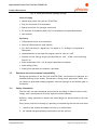
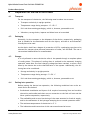
In the individual chapters, on the margin of the text occasionally symbols are
printed indicating the function of the respective paragraph. These indications are
important for the operation or the maintenance, or they indicate important descriptions or remarks, respectively:
Danger
All paragraphs in the user manual that contain indications to possible endangerments are marked with the alongside symbol.
Non-observance might implicate severe injuries! The instructions have to be
strictly adhered to.
Attention
All paragraphs marked with this symbol provide indications for the avoidance of
damages to the installation.
Hint
Paragraphs with this symbol give important hints for effective work.
The working steps that are described in logical order adjacent to this symbol
specify the most ergonomic way of operation.
Phocos AG
www.phocos.com
5
Subject to Change without notice
Hybrid Solar Power Fuel Cell Unit FC20/FC40
Identification
2
Identification
2.1
Product brand and type designation
Phocos® FC20/FC40
2.2
Product version / release no. (software) / document issue
Product version:
FC20/FC40
Software version:
V01.00 Build109
Issue:
10/2006
Phocos AG
www.phocos.com
6
Subject to Change without notice
Hybrid Solar Power Fuel Cell Unit FC20/FC40
Product Description
3
Product Description
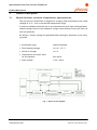
3.1
General functions, and areas of application; appropriate use
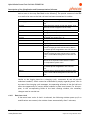
The fuel cell unit FC20/FC40 is assigned for charging lead accumulators with rated
voltages of 12 V / 24 V in the allowed temperature range.
It must be considered that the user or the manufacturer must input the applicationrelated voltage levels of the automatic charge control before putting the fuel cell
unit into operation.
On delivery, factory settings are parameterised ensuring an automatic cyclic charging mode.
• Accumulator type:
Lead accumulator
• Final charging voltage:
14.4 V / +25 °C
• Switch-on voltage:
11.5 V
• Temperature correction value
for accumulator:
• Stack voltage:
34.8 mV/K
1.8 V / stack
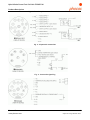
Fig. 1: Basic circuit diagram
Phocos AG
www.phocos.com
7
Subject to Change without notice
Hybrid Solar Power Fuel Cell Unit FC20/FC40
Product Description
3.2
Technical information and data
Performance data:
Power
(FC20 | FC40)
20 W | 40 W
Charging voltage
(12 V | 24 V)
10.5...14,7 V | 21,0…29,4 V
Maximum charging current
(FC20 | FC40)
2,0 A / 1,0 A | 4,0 A / 2,0 A
Hydrogen consumption
(approx. for the above given power)
(FC20 | FC40)
20 Nl / h | 40 Nl / h
Cooling
Water
Permitted accumulators
Lead accumulator/lead-gel accumulator 12 V
/ 24 V
Interfaces / Inputs / Outputs:
Data exchange
USB interface
GSM module (optional)
Analog inputs
2 x 0..10 V (in connection with GSM option)
Digital inputs
2 x 0..5 V (in connection with GSM option)
Digital outputs
2 x 0..5 V (in connection with GSM option)
Signal output
3 x 0..5 V
Gas supply:
Hydrogen
Purity 3.0 (99.9%) or better
CO content
< 20 ppm
Operation pressure hydrogen
Minimum 1 bar – maximum 10 bar
Connection
Self-sealing snap closing
Process air
Clean ambient air, good aeration
Environmental conditions
Ambient temperature range
-25…+50 °C (if the device is operationally connected)
Storage temperature
Phocos AG
www.phocos.com
Minimum 5°C (system temperature)
8
Subject to Change without notice
Hybrid Solar Power Fuel Cell Unit FC20/FC40
Product Description
Degree of protection
Pollutants
IP 54
The ambient air must not contain increased concentrations of sulphur compounds, carbon monoxide, ammonia, chlorine compounds, solvents and
dust.
Casing
Dimensions
415 mm x 335 mm x 235 mm
Material
Plastic material
Mass
About 9.5 kg
Connections
Phocos AG
www.phocos.com
9
Subject to Change without notice
Hybrid Solar Power Fuel Cell Unit FC20/FC40
Product Description
Fig. 2: Situation of the connections and the control elements
Fig. 3: Disposable connections
Fig. 4: Connection signalling
Phocos AG
www.phocos.com
10
Subject to Change without notice
Hybrid Solar Power Fuel Cell Unit FC20/FC40
Product Description
Fig. 5: Connection external hydrogen storage
Scope of supply
• Hybrid solar power fuel cell unit FC20/FC40
• Plug for connection of accumulator
• Special connector for hydrogen connection
• PC software for Windows (2000, XP) for visualisation and parameterisation
• User manual
Optionally
• Temperature sensor for accumulator
• Internal GSM module for data transfer
• IN / OUT interface (2 x digital out, 2 x digital in, 2 x analog in); comprised in
GSM option
• Implementation of user-specific program tools for user-IN / OUT
• Pressure control fittings for gas cylinders 200 bar, on 0 – 10 bar, and connecting
hose 2.5 m
• Solar accumulator 12V / 6.6 Ah (other capacities on request)
• Steel casing (IP 64)
• Putting into operation at customer’s premises
3.3
Emissions and environmental compatibility
During the operation of the fuel cell unitFC20/FC40, low amounts of hydrogen are
emitted (flushing of the anode). Furthermore, during power generation, water (water vapour) is generated escaping together with the hydrogen on the bottom part of
the device.
3.4
Safety information
The fuel cell unit was developed and produced according to state-of-the-art technology, and it was subject to a safety inspection before delivery.
However, faulty operation or misuse can cause danger for persons and for the fuel
cell unit.
Every person involved in setting up, operating or maintaining the fuel cell unit must:
1.
read this user manual and adhere strictly to its instructions;
2.
be trained and appropriately instructed for his/her activity.
Phocos AG
www.phocos.com
11
Subject to Change without notice
Hybrid Solar Power Fuel Cell Unit FC20/FC40
Product Description
3.4.1
Safety measures on the installation location
Danger
When hydrogen is used as energy source, fire and explosion hazards are generally increased
The use of open fire, as well as smoking is strictly forbidden in this area.
The rooms in which the fuel cell unit will be operated must dispose of the following:
• Local removal by suction for hydrogen on the installation location, or
• a room air suction or aerating installation on the room ceiling enabling safe exhausting of the rising hydrogen out of the room.
The installation location has to be chosen in a way that product water escaping
from the bottom of the fuel cell unit in the course of operation cannot cause damages or endangerments.
Attention
No electrical or electronic components, or other components sensitive to water
are permitted below the fuel cell unit.
3.4.2
Remaining endangerments
The described product complies with the state-of-the-art and the generally accepted safety-related rules. However, the occurrence of dangers cannot be excluded.
The remaining endangerments in connection with the use of the device are due to:
• The use of hydrogen accumulators and the associated fittings including the connecting pipes to the device.
• The use of lead accumulators and their possible improper use.
In this context, the regulations applying to these components have to be considered
and observed according to the installation location.
3.4.3
Qualification of the operating staff
Only persons with technical (preferably electrotechnical) training who are able to
realise the connections in a professional manner are allowed to put the fuel cell
unit into operation and to connect it.
For the operation of the PC user interface belonging to the scope of supply, basic
knowledge on the current WINDOWS system software is required. The respective
details can be found in the attached detailed program description.
Phocos AG
www.phocos.com
12
Subject to Change without notice
Hybrid Solar Power Fuel Cell Unit FC20/FC40
Product Description
4
Preparation for the Use of the Product
4.1
Transport
For the transport of the device, the following must be taken into account:
4.2
•
Transport exclusively in upright position
•
Temperature range during transport: +5..+50 °C
•
Soil- and dust-resisting packaging, which is, however, permeable to air
•
Vibrations, strong shocks, impacts and blows have to be avoided
Packaging
Generally, for the transport or the shipment of the device, respectively, packaging
that is suitable for the destination and for the object, and that is environmentalfriendly has to be used.
As the device itself has a degree of protection of IP54, a packaging type has to be
selected for transport that prevents penetration of water, soil and dust. The use of
conventional dehumidifiers is recommended.
4.3
Storage
It is only allowed to store the device after it has passed through a complete phase
of cooling down. This phase of cooling down is realised in the automatic charging
operation mode after the final charging voltage has been reached, or after a shut
down by the device due to the characteristics of the system. Additionally, the following has to be considered:
4.4
•
Storage exclusively in upright position
•
Temperature range during storage: +5..+50 °C
•
Soil- and dust-resisting packaging, which is, however, permeable to air
Putting into operation
Before putting the device into operation, the following conditions have to be ensured and to be checked:
• Professional installation and layout of all required connecting lines and conduits
(electricity and media) and their correct connection to the fuel cell unit and the
other system components, respectively.
• The availability and correct functioning of the room aeration for fresh air supply,
and for the exhaustion of the hydrogen escaping due to normal operation mode.
• The minimum temperature of the device is +5° C.
• The indications and instructions of this user manual must be known.
Phocos AG
www.phocos.com
13
Subject to Change without notice
Hybrid Solar Power Fuel Cell Unit FC20/FC40
Product Description
4.4.1 Choice of the accumulator
The fuel cell unit is designed for cyclic operation. That means that the power supply system must be dimensioned in a way that the average power taken from the
accumulator is less than the power supplied by the fuel cell unit. Special attention
must be paid to the capacity of the chosen accumulator. In dependence of the energy demand of the installation to be supplied with power, the capacity of the accumulator determines the frequency and the duration of the charging cycles. If the
fuel cell unit is used in areas where outside temperatures only slightly above or
even below 0 °C can be expected, the duration of the charging cycles should be optimised in order to reach high energy efficiency. During their operation, the fuel
cells provide enough heat to ensure optimum temperature conditions in the interior
of the device. However, in case of the above-mentioned low outside temperatures,
this requires several hours of operation of the device. In order to keep the heating
period as short as possible, a part of the generated electrical energy is temporarily
used for an internal heating element. The corresponding amount of energy will be
derived from its normal purpose – the charging of the accumulator. In this case, full
cooling down due to long charging pauses should be avoided in order to avoid fulllength heating periods. Conditions for which charging pauses in case of temperatures distinctly below 0 °C do not take longer than 24 hours can be considered as
energetically favourable.
For the determination of the optimum accumulator capacity, the essential influencing factors are the temperatures to be expected, and the average power consumption of the application. Appropriate recommendations will be provided in the context of the initial putting into operation, or on request.
Phocos AG
www.phocos.com
14
Subject to Change without notice
Hybrid Solar Power Fuel Cell Unit FC20/FC40
Product Description
4.4.2
Connection of the hydrogen accumulator
For hydrogen supply, the parameters mentioned above are relevant. For a safe connection or exchange, respectively, of the pressure vessel the following sequence
has to be followed:
1. Switch-off the fuel cell unit FC20/FC40 (red key).
2. Pull the accumulator plug. The power supply by the fuel cell unit will be interrupted.
3. Close the hydrogen cylinder.
4. Close pressure line at the pressure control fittings of the gas cylinder.
5. Screw off fittings from the hydrogen cylinder (attention: left-handed thread!)
6. Exchange hydrogen cylinders.
7. Screw the fittings on the new cylinder.
8. (Only in case of initial putting into operation) detach snap closing of the hydrogen supply from the fuel cell unit.
9. Turn on hydrogen cylinder.
10. Open the pressure line at the pressure control fittings of the gas cylinder.
11. (Only in case of initial putting into operation) deaerate the supply pipe to the
fuel cell unit (filling it with hydrogen).
12. (Only in case of initial putting into operation) connect the snap closing to the
fuel cell unit.
13. Connect the accumulator plug to the fuel cell unit.
14. Carry out a leak test with a gas leak spray
The hydrogen pressure on the device must be between at least 1 bar and at most 10
bars.
4.4.3
Connections on the device
Connection H2, connector panel
To this connector, the hydrogen supply line is connected. The supply of the fuel cell
unit with hydrogen is necessary for its operation.
Connection A (accumulator), connector panel
This connector is used for the connection of the lead accumulator to be charged. A
connected accumulator is necessary for the operation of the fuel cell unit (pin as-
Phocos AG
www.phocos.com
15
Subject to Change without notice
Hybrid Solar Power Fuel Cell Unit FC20/FC40
Product Description
signment: +/1+ | -/1-), whereas the accumulator voltage must be within the limits
of the specified range of the charging voltage.
USB connection, connector panel
The USB connector connects the fuel cell unit with a computer. The visualisation
and parameterisation software contained in the scope of supply enables easy access
to all functions of the fuel cell unit. Besides the possibilities of parameterising,
data acquisition, data storage, and visualisation, complete access to the optional
GSM module is assured (see 6.4.7).
Connection U (user-specific connection), connector panel
If a GSM module (optional) is available, the user can use the connector U. Besides 2
analog inputs it has 2 disposable digital inputs and 2 disposable digital outputs (pin
assignment: see 3.2). The inputs and outputs can be logically connected with each
other. As a result of these logical connections, respective messages can be transmitted by SMS and/or e-mail. For example, the level of a digital output can change
and/or an SMS and/or e-mail can be transmitted when a threshold value has been
exceeded for an analog output. Inversely, level changes for digital outputs can be
triggered by command sequences transmitted by SMS or e-mail.
Connection M (monitored information), connector panel
By level changes of certain pins of this connector (pin assignment: see 3.2) the fuel
cell unit provides external status signals. These signals can be processed by the user
if required.
Connection S (H2 accumulator), connector panel
This connection (pin assignment: see 3.2) offers the opportunity for the user to provide the fuel cell unit with additional information about the connected hydrogen
accumulator (optional manometric switch) or the accumulator to be charged (1 wire
temperature sensor). The manometric switch can be used to signalise the state
“hydrogen accumulator almost empty”. The temperature measurement on the accumulator serves for the determination of the exact final charging voltage of the
accumulator (temperature-dependent adaptation of the final charging voltage).
Phocos AG
www.phocos.com
16
Subject to Change without notice
Hybrid Solar Power Fuel Cell Unit FC20/FC40
Product Description
Attention
The length of the connecting lines on the installation location must not exceed
3 m because otherwise problems with EMC (interference signals) may occur. For
lengths above 3 m, screened signal cables have to be used.
The laying of the required electric cables must be carried out by a professional
electrician.
4.4.4
Putting the device into operation
After it has been checked that the lead accumulator and the hydrogen supply have
been connected to the device, that the accumulator voltage is within the specified
range of the charging voltage, and that the hydrogen supply is ensured, the device
is operational. Now, the charging process can be started manually by pressing the
green key on the device, or it starts automatically when the supply voltage drops
below the preset voltage level. The initialisation and all operating states will be
signalised by different flashing patterns of the two LED on the device (see 5.4).
Phocos AG
www.phocos.com
17
Subject to Change without notice
Hybrid Solar Power Fuel Cell Unit FC20/FC40
Operation Manual
5
Operating Manual
5.1
General functional description
The fuel cell unit FC20/FC40 serves for charging 12 V / 24 V lead accumulators used
for optional applications. Pure gaseous hydrogen is the primary energy source.
5.2
Operating modes
5.2.1
Accumulator voltage recognition
FC20/FC40 disposes of automatic accumulator voltage recognition. For each (new)
connection of an accumulator (corresponding to “cold start” of the device) the accumulator voltage is measured several times, and the measured values are compared with the parameterised accumulator voltage. If this comparison shows a discrepancy, the device will be automatically adapted to the determined accumulator
voltage, and for all relevant parameters the default values for the respective accumulator voltage will be selected. If the measured voltage is:
Attention
1. greater than 17V for the parameterised 12 V accumulator type: Æ Adaptation to 24 V accumulator type
2. lower than 18V for the parameterised 24 V accumulator type: Æ Adaptation to 12 V accumulator type
The whole process takes about 1 second, and it is accompanied by simultaneous
flickering of both LED. After the adaptation of the accumulator voltage, the device
will be restarted.
5.2.2
Initialisation of the FC20/FC40
After the automatic accumulator voltage recognition, the actual initialisation of the
device takes place. During initialisation, several hardware tests and basic adjustments are carried out. The initialisation takes about 2 to 3 seconds, and the process
is signalized by the LED (Fig. 6).
5.2.3
Initialisation of the GSM module
If the fuel cell unit is equipped with the optional GSM module, this module will be
initialised, too. The initialisation takes about 10 to 15 seconds, and it is signalized
by the LED (Fig. 6).
5.2.4
Charging process
The device works automatically, and the charging process starts and ends, respectively, after the adjustable minimum voltage or final charging voltage for the accumulator, respectively, are reached (Fig. 6).
Phocos AG
www.phocos.com
18
Subject to Change without notice
Hybrid Solar Power Fuel Cell Unit FC20/FC40
Operation Manual
Shutdown criteria
With respect to possible shutdown criteria, see description of the data of the protocol file (Tab. 2).
Purging
PEM fuel cells operated with hydrogen show discontinuous behaviour during their
operation. Even at constant external conditions, such as temperature, quantity of
the supplied air and hydrogen and their constant quality, the operation characteristics can change. These changes often cause a reduction of the electrical power output. Such effects are mostly due to the reduction of the reactive catalyst surface by
accumulation of inert gas components, to inhomogeneous distribution of humidity
over the whole surface of the membrane, and to inhomogeneous current density
distribution.
A simple measure to reduce this effect is the so cold purging of the hydrogencontaining component of the device. For this reason the valve situated at the stack
exit (H2 side), which is closed during normal operation, will be opened for a short
time. A small quantity of unused hydrogen will be blown-off, but the stack can now
be operated stably with distinctly higher power for a considerable time. An indicator for the necessity of purging is for example the output current of the stack at
constant stack voltage (see 6.4.1).
5.2.5
Cooling phase
Independent of the reason of the end of the charging process, the cooling phase
sets in after the process has stopped. For each decrease of stack temperature of 5
Kelvin the pump will be switched-on for about 1 s in order to remove condensed
humidity from the stack. This phase is time-independent, and the only criterion for
its end is the difference between stack temperature and ambient temperature. If
this difference is lower than 2 K, the cooling phase stops. The cooling phase can be
aborted by shortly pressing the red key.
5.2.6
Stand-by mode
After the cooling phase, the device is in stand-by mode. Temperature and accumulator voltage are still surveyed, and the possibility to communicate through the USB
interface is maintained. The stand-by mode is signalised by the LED (Fig. 6).
5.2.7
Heating mode
If the stack temperature becomes lower than the set minimum value (e.g. in case
of frost in outdoor use) the device switches into heating mode. In this mode, a part
of the generated electrical power is used for charging the accumulator, and the
remaining part is used for heating the relevant components. If during the heating
Phocos AG
www.phocos.com
19
Subject to Change without notice
Hybrid Solar Power Fuel Cell Unit FC20/FC40
Operation Manual
mode the accumulator voltage reaches the value of the final charging voltage, the
whole electrical power generated by the fuel cells is used for heating.
5.3
Operation with GSM module (optional)
The optional GSM module enables the communication with the fuel cell unit through
mobile network. On the one hand, the device can send system information or userspecific information (e.g. events at the user-inputs or information derived from
them, respectively) by SMS and/or e-mails. On the other hand, the fuel cell unit can
receive and process command sequences by SMS and/or e-mail.
Phocos AG
www.phocos.com
20
Subject to Change without notice
Hybrid Solar Power Fuel Cell Unit FC20/FC40
Operation Manual
5.4
Messages / signals
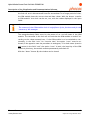
The fuel cell unit generates the following messages and provides them as electric
signals at the connection M (messages):
Device in operation
This signal is set when the fuel cell unit is in operation and charges the accumulator.
- Connection M, digital out pin 2, open collector, maximum 10 mA.
- Additionally, the green LED is flashing.
Common fault
This signal is set when the accumulator voltage drops below the preset value. This
can only occur in case of failure.
- Connection M, digital out pin 3, open collector, maximum 10 mA
Low pressure H2 accumulator
This signal is set when the pressure in the hydrogen accumulator drops below a
preset value (e.g. 20 bar). The precondition for this signal is that a manometric
switch is connected with connection S (H2 accumulator), pin 8.
- Connection M, digital out pin 4, open collector, maximum 10 mA
- Additionally, the red LED is flashing.
Additionally to the signalling of messages by setting digital outputs of the connection M, relevant information are signalised by flashing patterns of both LED of the
control panel, too.
LED green
t
LED red
STATUS OF DEVICE
t
INITIALIZATION GSM-FUNCTION
1s 1s
1s 1s
1s
1s
INITIALIZATION
0,2s 0,2s
READY FOR START UP
2s
1s
1s
DEVICE CHARGES ACCUMULATOR
2s
0,2s 0,2s
LOW PRESSURE OF H2 BOTTLE
1s
1s 1s
FAULT H2 SUPPLY
1s
Fig. 6: Flashing patterns of the LED
Phocos AG
www.phocos.com
21
Subject to Change without notice
Hybrid Solar Power Fuel Cell Unit FC20/FC40
Description of the Visualisation and Parameterisation Software
6
Description of the Visualisation and Parameterisation Software
6.1
Preliminary remarks
Together with the device, a parameterisation and monitoring software for PC is
supplied. In the following, details as to function and handling of this software are
given.
System requirements
Hardware:
- Customary medium performance PC with USB interface
System software:
- MS Windows (2000, XP)
6.2
Installation
The software is installed like any common Windows software:
1. Insert data carrier
2. Begin installation by running setup.exe
3. Follow the commands of the installation program (enter path, etc.)
a. Installation step back by clicking on back
b. Abort installation by clicking on abort
4. Finish installation by clicking on finish
6.3
Uninstall process
If the software is to be removed from the hard disk, proceed as follows:
1. Open the Windows Start Menu.
2. Open the Control Panel.
3. In the control panel, click on the Software symbol.
A list of the existing programs is shown.
4. From this list, select the symbol for FC20/FC40.
5. Click on Remove. The software will now be uninstalled.
6.4
Structure of the Software
6.4.1
Basic settings
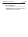
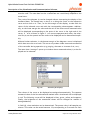
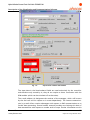
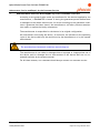
After selecting the menu item ‘Window Æ basic device settings’ the dialogue window for the basic device settings opens up. Here, all significant settings for the
running operation of the device can be carried out.
Phocos AG
www.phocos.com
22
Subject to Change without notice
Hybrid Solar Power Fuel Cell Unit FC20/FC40
Description of the Visualisation and Parameterisation Software
Indication
If an invalid value is entered in a data field (value outside of the permitted range for this data field), an indication appears:
Accumulator settings
In (7), a preselection is possible between a 12V and a 24V accumulator. If the existing setting is modified, the corresponding default voltage levels for the begin and
the end of the charging processes will be set. For this, a customary lead-acid accumulator is assumed as it is commonly used as starter battery for motor vehicles.
Fig. 7:
Basic settings
With respect to a temperature of +25°C it can be assumed that an accumulator as
shown in the example above is discharged when its voltage has dropped below 11.5
V. In the contrary, a voltage of about 14.4 V indicates that it is fully charged. If,
beyond this voltage level, the charging process continues, the water in the accumulator begins to decompose in its gaseous components. If the corresponding loss of
water will not be compensated, the accumulator will be permanently damaged.
That means that overcharging has to be avoided. For the final charging voltage depends on the accumulator temperature, an additional parameter can be set that
adapts the effective recognition of the final charging voltage according to the temperature. The correct value for the influence of the temperature on the rated valPhocos AG
www.phocos.com
23
Subject to Change without notice
Hybrid Solar Power Fuel Cell Unit FC20/FC40
Description of the Visualisation and Parameterisation Software
ues of the accumulator voltages must be taken from the manufacturer’s data of the
accumulator.
Danger
If values are entered which are within the permitted range for the data field but
not permitted for the accumulator (see data sheet of the accumulator) the accumulator can be destroyed, or the device can be damaged, respectively.
Purging current
When the current drops below the purging current set in (5), the process of purging
will be started. If the time between two purgings is in average about 2 minutes, optimum setting can be assumed. Longer pauses between the purgings would be of
advantage, but the average output power would be lower than in case of more frequent purgings. However, if in the case of a relatively lowly set purging current the
output power seems to be sufficient for the actual application, and the device is
running stable for a considerable time, the lowest possible value should be chosen.
This will lead not only to a minimum hydrogen consumption but also for a longer
service life of the stack.
Operating voltages
In (3) the operating voltages of the stacks are set. The total value will be used by
the built-in DC-DC transformer to dynamically adjust the electrical power required
from the stacks so that this total voltage is always exactly reached (constant voltage operation).
As standard, a single stack as it has been used for the FC20/FC40 (consisting of
three cells) is operated with 1.8 V (corresponding to 0.6 V per cell). This voltage is
a good compromise between efficiency, power, operation characteristics and service life. According to the concrete stack properties, values that are slightly different of the values mentioned above can be preset or set.
If the FC20/FC40 is provided with 2 stacks, slightly different operating voltages for
the stacks are possible or reasonable, respectively. The voltage stabilisation mentioned above refers to the sum of both stack voltages. For this reason it is possible
that the voltages that are measured during operation, and the actual monitored
voltages (for example in the diagrams or in the general chart) can differ from the
rated voltage levels preset here. If the voltage difference between the two rated
voltages of the stacks exceeds a critical value, purging takes place. If purging is not
successful, the device will be shut down.
Open-circuit voltages
The rated open-circuit voltages to be entered in (4) are significant only for the start
of a charging cycle. The comparison between the actual open-circuit voltages and
Phocos AG
www.phocos.com
24
Subject to Change without notice
Hybrid Solar Power Fuel Cell Unit FC20/FC40
Description of the Visualisation and Parameterisation Software
the rated open-circuit voltages before the start of the device provides a first indication for the operatability of the stacks. If the supply with hydrogen and air are
ensured, the measured voltage for each stack should be 2.4 V (0.8 V per cell) or
higher when no current is drained. In this case the stacks are operational, and by
successively increasing the drained current, the electrical output power can be increased. The stack voltages will consequently decrease gradually. After the operating voltage is reached, this value will be kept constant.
The operating stack voltage in particular has a far-reaching influence on the operation characteristics and the service life of the stacks. In extreme cases, permanent
damages can occur within short time if a too low value has been set for the voltage.
Therefore, only staff with special knowledge in the field of fuel cells should be allowed to modify the settings.
Temperatures
The stacks are situated in a container with coolant. On the one hand, this coolant
will cool the stacks efficiently in case of high ambient temperatures, and on the
other hand, its great thermal capacity will expand the cooling phase in case of low
ambient temperatures. The heat emission of the stacks to the surrounding liquid
leads especially in case of a start at low temperatures to layer formation and thus
to an unfavourable temperature distribution. For this reason, a pump that has been
built in the container makes circulate the liquid. For reasons of energy saving, this
pump is not operated continuously. In the topmost input field for the different
temperature settings (8), within the range between 2 K and 10 K it can be determined for which increase of temperature (in K) the circulation pump will be
switched on. In the moment of switching-on the pump, the corresponding temperature sensor will measure a temperature drop. For the stack will continue to heat
the container, after a certain period of time the temperature at which the pump
has been switched on will be reached again, and now the pump will be switched off.
This leads to a step-by-step march of the stack temperature. The individual steps
are denominated here as temperature plateaus.
The other temperature settings are described by their denominations.
Switch on / -off with external signals
There is an other option as switch on and –off the fuel cell unit depended on the
voltage by the accumulator. This is an option for external switching with separate
ports.
Is the Dot at (9) in the basic setting are set, the fuel cell unit switches on when a
‘1’-Level is detected at the digital-user input number one. To dedect this happening safely, the level must be active at least for 0.2 seconds. Before the inverted
Phocos AG
www.phocos.com
25
Subject to Change without notice
Hybrid Solar Power Fuel Cell Unit FC20/FC40
Description of the Visualisation and Parameterisation Software
happening can be dedected, the active Level have to take back (use the digitaluserinput number two in the same way to switch off).
Hint
Speciation settings for the digital-userinputs by using GSM-functions must be
deactivated.
Be carful that at the digital user-inputs never have an active level at the same
time.
Loading / saving the set of parameters
The set of parameters actually shown can be transferred by the “transmit” button
in the menu item “to device” to the FC20/FC40. By “load” and “save” in the menu
item “from/to file” the actual set of parameters can be stored on the data carrier,
or a stored set can be loaded from there. Furthermore, with “load” and “save” it is
possible to load a set of parameters that has been sent by e-mail, or to transmit the
actual set as e-mail (optional GMS module required). The procedure of loading and
converting a set of parameters from an e-mail is described in 6.4.6 by Error! Reference source not found..
6.4.2
Schematic overview
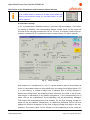
After selection of the menu item ‘Window Æ schematic overview’ an animated
scheme will be presented. It shows the device, together with its connected components. Additionally, the graphical presentation and the corresponding captions indicate the state of the components.
Fig. 8: Schematic overview
6.4.3
File types / file denominations
The software offers numerous possibilities for data storage. The data are stored in 4
different file types. With exception of the data stored in a special format into *kfg
files all data are stored in ASCII format.
Phocos AG
www.phocos.com
26
Subject to Change without notice
Hybrid Solar Power Fuel Cell Unit FC20/FC40
Description of the Visualisation and Parameterisation Software
File extension
1
*.hst
2
*.hss
3
*.kfg
4
*.prt
Stored information
All charging processes
(table history)
Last charging process
(Fields below table history)
Device configuration
(Basic settings device)
Logging of relevant data
(runs in background)
Tab. 1:
Attach new
data
File name
changeable
no
yes
yes
yes
no
yes
no
no
Overview file types
For the automatically generated and proposed standard file names the following has
been specified, independent of whether the names can be modified afterwards or
not:
Example: FC040120192006002_00274_24.prt
~~-----~~~---~~~~----- ~~~~~~~~
| | | | | | |_______ Current count of the operating hours meter
| | | | | |______________Serial number from digital type plate
| | | | |__________________Year of construction
| | | |____________________ Week of construction
| | |________________________Nominal output voltage (here: 12.0V)
| |___________________________Nominal power of the device [stack(s)] (here: 45W)
|______________________________Device type “Fuel Cell Unit”
6.4.4
Recorder function
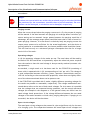
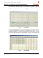
After selecting the menu item ‘Tools Æ recorder’, the window for the graphical
presentation of the measured values opens up in the lower half of the screen.
Fig. 9: Recorder window
The preset length of the timeline (3) is two minutes. After the start, the previously
selected measured values are shown as coloured curves going from left to right in a
unit diagram. When the right margin of the indicating range is reached, the display
changes into rolling mode. Now, the oldest values are displaced outside the display
on the left margin. The measured values are not stored beyond the 2 minutes during which they are displayed. This function only serves for real-time monitoring of
the operation of the fuel cell unit. In order to record the measured values for reaPhocos AG
www.phocos.com
27
Subject to Change without notice
Hybrid Solar Power Fuel Cell Unit FC20/FC40
Description of the Visualisation and Parameterisation Software
son of subsequent evaluation (even for longer periods of time), the logging function
must be used. The time data on the x-coordinate are continuously adapted to the
actual time.
The y-axis of the diagram (1) can be changed without interrupting the display of the
measured data. The easiest way to do so is to bring the curser to the respective
curve and to click on it. Then, on the left margin of the display, a scale with the
colour of the selected curve and with the corresponding values appears. Additionally, on the lower margin the value and the unit of the most recent measured value
will be displayed (corresponding to the point of the curve in the right end of the
curve). If – as it is shown in figure 9 – two curves superpose each other, the selective list (4) can be opened and the scale to be displayed can be determined explicitly.
Without further selection, in the bottom margin of the diagram a curve is displayed
which does not refer to a scale. This curve only makes visible interventive measures
of the controller during operation (e.g. purging, decrease or increase of air, etc.).
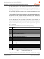
The menu item “settings!” opens up a window where measured values (1) to be displayed can be selected.
Fig. 10:
Selection for display
The colours of the curve to be displayed are assigned automatically. The topmost
measured value of the list selected and marked with a checkmark will be displayed
in red. The following curves will be displayed in blue, green, yellow and magenta.
Finally, the brightness of the mentioned colours will be changed for reasons of
distinguishability.
In field (2), time resolution can be determined. The preset value is 60 samples per
minute. This value can be varied between 12 (corresponding to 5 seconds for each
Phocos AG
www.phocos.com
28
Subject to Change without notice
Hybrid Solar Power Fuel Cell Unit FC20/FC40
Description of the Visualisation and Parameterisation Software
value) and 300 (corresponding to 5 values per second). However, only certain settings are really practicable or reasonable, respectively. In any case, the preset
value of 2 minutes for the display time will remain constant, but the number of the
individual measurements per unit of time that will be displayed will change.
6.4.5
Logging function
Pressing the “start” button (‘logging’) in the window with the schematic overview
starts the logging process for all measured values and status information. Automatically, a ASCII file with the extension *.prt is generated in which the data are stored
in form of a table with 28 columns. The first row of each file states the sampling
frequency for the data. The columns are separated by a tab stop. Deliberately,
decimal separators have not been used in order to avoid data import problems with
PC programs in different language versions.
Independent of the set time period (sampling rates between 300/min and 1/min are
possible), after 1 hour a new file with running numbering in the automatically generated file name is generated.
Attention
If the highest rate is selected, the file size after 1 h of recording is about 1.7 MB.
The contents of the individual columns have the following meaning:
Column Meaning
1
2
3
4
5
6
7
8
9
Phocos AG
www.phocos.com
Time in 0.1s with respect to the start time
For example, the entry 36076 means that the following columns contain values
that have been measured after 1h 0m 7.6s since start.
Output current of the DC-DC-transformer in 0.01A
For this value it must be taken into account that it does not represent the current available for charging the accumulator, because the own consumption of the
device must be subtracted from it. In case of starting at low temperatures, own
consumption can mean a considerable amount because for reasons of optimising
the operating conditions for the fuel cell most of the available energy will be
used for heating the system.
Stack current in 0.01A
This value is strongly connected with the before-mentioned output current of the
transformer because its calculation within the controller implies the output voltage and the efficiency.
Actual purging current in 0.01A
This column represents the stack current that has been preset for the stack current in the basic device settings, and which varies in dependence of interventive
measures such as purging or short-term air decrease/increase, etc., influencing
the operation of the device. During operation of the device at temperatures below the specified operating temperature, the values in this columns vary, because during this phase, this parameter is adjusted dynamically.
Voltage of stack 1 in 0.01V
Voltage of stack 2 in 0.01V
Output voltage - identical with voltage on accumulator – in 0.01V
Voltage at analog input 1 of the user interface in 0.01V
Voltage at analog input 2 of the user interface in 0.01V
29
Subject to Change without notice
Hybrid Solar Power Fuel Cell Unit FC20/FC40
Description of the Visualisation and Parameterisation Software
10
11
12
13
14
15
16
17
18
for internal use
for internal use
Temperature at purging valve or air exit, respectively, in 0.1°C
Temperature at accumulator in 0.1°C
Temperature in stack container in 0.1°C
Ambient temperature in 0.1°C (measured in the interior of the device)
for internal use
for internal use
for internal use
Decimal in the range 0..32767
The bits represent recognised failures or indications.
Bit 0 – open-circuit voltage during start ('0' = reached,
'1' = not reached)
Bit 1 – start phase ('0' = successfully terminated,
'1' = with failure, or manually terminated)
Bit 2 – normal run ('0' = no failure,
'1' = failure occurred)
Bit 3 – Intervention due to drop in power e.g. purging ('0' = off, '1' = on)
Bit 4 – cooling phase ('0' = no failure, '1' = failure occurred)
19
20
21
22
23
24
25
26
27
28
Bit 5 – reserved
Bit 6 + 7 – Shutdown due to
00 Final charging voltage has been reached, or manual shutdown
Accumulator had already been fully charged, but minimum temperature has
01
been reached only later
Temperature of the device above permitted maximum (cooling failure, or
10
ambient temperature to high)
Stack voltage of the device was below the permitted minimum (transformer
11
failure, or other failure)
Bit 8 – emergency shutdown due to action of manometric switch at too low pressure ('0' = not triggered, '1' = triggered)
Bit 9 – device with 2 stacks has determined that the stack voltage difference was
too high
Bit 10 – either a permanent device failure, or the accumulator has been disconnected
Bit 11 – manometric switch at MHS or at H2 cylinder has been triggered
Bit 12 – temperature sensor at stack defective
Bit 13 - '1' – sufficient number of correct temperature measurements has been
determined
Bit 14 - '1' – purging valve rusted in or frozen; anyway, purging without effect
Bit 15 - '1' – Interruption due to too frequent purging
for internal use
for internal use
for internal use
for internal use
for internal use
for internal use
for internal use
for internal use
for internal use
Tab. 2:
Phocos AG
www.phocos.com
Column overview of log file *.prt
30
Subject to Change without notice
Hybrid Solar Power Fuel Cell Unit FC20/FC40
Description of the Visualisation and Parameterisation Software
6.4.6 History charging cycles
After selecting the menu item ‘window Æ read out history’ it is possible to read out
relevant data with respect to the previous charging processes from the device, to
visualise and to store them.
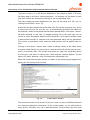
Fig. 11:
History data (1)
Below the still dimmed table there is a “read out” button. If this button is clicked,
the data are read line by line from the fuel cell unit and entered into the list. The
maximum total number of stored charging processes is 50. After the 50th charging
process, the respective oldest entry will be deleted. However, cycle numbering will
continue.
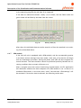
Fig. 12:
Phocos AG
www.phocos.com
History data (2)
31
Subject to Change without notice
Hybrid Solar Power Fuel Cell Unit FC20/FC40
Description of the Visualisation and Parameterisation Software
The real entries depend on the respective device equipment and configuration.
When the history has been read out completely, the content of the whole table can
be stored in a file for reasons of further processing or storage. For this, the button
“store” (5) must be clicked.
The proposed file name can be changed at will. The preset file extension is *.hst. It
cannot be modified by the user.
In order to export the data to other applications it must be considered that no special separators are used. All spaces are blank characters. For the separation of
decimals, points are used (if the basic settings are not taken into account, Excel
would, for example, interpret the data as dates).
After the table has been read out, possibly in the column “failure/indication” an
entry in hexadecimal format can be found in which each bit position corresponds to
a particular meaning. If one clicks on one of these fields with the left mouse button,
the plain text form of the meaning of the entry will be displayed in the right lower
area of the window.
The contents of the individual columns have the following meaning:
Column Meaning
1
2
3
4
5
6
7
8
9
10
11
12
13
14
15
16
17
18
19
20
21
22
23
24
Cycle number, counted continuously during the entire service life of the device
Start time in real time (date and time)
Stop time in real time (date and time)
Charging period in days, hours, minutes, seconds
Previous charging pause in days, hours, minutes, seconds
Ambient temperature minimum in °C
Ambient temperature maximum in °C
Stack temperature minimum in °C
Stack temperature maximum in °C
Accumulator temperature minimum in °C
Accumulator temperature maximum in °C
MHS temperature minimum in °C
??
MHS temperature maximum in °C
??
Output current minimum in A
Output current maximum in A
Stack voltage minimum at stack1 in V
Stack voltage maximum at stack1 in V
Stack voltage minimum at stack2 in V
Stack voltage maximum at stack2 in V
Accumulator (output) voltage minimum in V
Accumulator (output) voltage maximum in V
Indications or disturbances, respectively, during the charging cycle
Longest distance between two purgings in seconds
Number of purgings during the entire charging process
Tab. 3:
Column overview history *.hst
In the green-bordered area of the window “history” the respective last charging
Phocos AG
www.phocos.com
32
Subject to Change without notice
Hybrid Solar Power Fuel Cell Unit FC20/FC40
Description of the Visualisation and Parameterisation Software
process can be loaded from the memory of the fuel cell unit by clicking on the
“read out” button (1). It will then be displayed in the respective fields. If an entry
has been made in the field “failure/indication”, its meaning will be shown in plain
text form without the necessity of clicking on the corresponding field.
The (last) charging process displayed in this way can be stored to a file, too, by
clicking on the button “store” (3).
Unlike the file that contains the whole table, this file has the extension *.hss, and it
is a pure text file, too. For this file, too, an automatically generated file name will
be proposed, unless in the popup that has been opened before, the option “attach”
has been selected. In this case, an already existing file of the same type can be
chosen to which the present data set will be attached. If this type of storage is used,
a table whose structure is identical with that described above will be generated.
This variant is particularly useful when the GSM functions will be applied (see below).
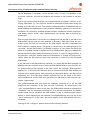
Clicking on the button “import data” allows to display values in the fields within
the green frame that do not come from a connected fuel cell unit but from the content of a received e-mail. The window that opens up “open file” preferably allows
the file type *.eml which is used by the e-mail program “Outlook Express” for the
export of e-mails. However, other file extensions are possible, too.
When the chosen file has been opened, a window of the following type appears displaying the full content of the e-mail.
Fig. 13:
E-mail import window
The concrete structure and content of such an e-mail can be very different because
the numerous additional information of the e-mail header (1) are influenced by
many factors. Providers, too, use to add information. For this reason the user must
Phocos AG
www.phocos.com
33
Subject to Change without notice
Hybrid Solar Power Fuel Cell Unit FC20/FC40
Description of the Visualisation and Parameterisation Software
mark the actual message transmitted by the fuel cell unit (2) in order to point out
to the operating program the real data to be imported.
If the data are marked the button “ready” (3) is clicked, and the fields within the
green frame will be filled by the data from the e-mail.
Fig. 14:
History data (3)
After that, this individual data set can be stored to a file or be attached to an existing file as described above.
6.4.7
GSM module
If the fuel cell unit is equipped with a GSM module, and the corresponding entries
in the basic devices settings have been made, each start of the device will begin
with an initialisation procedure. During this phase, both LED will shine together for
several seconds. The exact duration cannot be predicted precisely because the receiving conditions have a certain influence on it.
After a program start with correct functioning communication, the PC application
will determine whether the device disposes of a GSM module or not. In case of an
available GSM module, in the menu item “tools” the sub-item “GSM settings” will
be activated. If this menu item is selected, the following can be seen:
Phocos AG
www.phocos.com
34
Subject to Change without notice
Hybrid Solar Power Fuel Cell Unit FC20/FC40
Description of the Visualisation and Parameterisation Software
Fig. 15:
Information window GSM module
The input data in the blue-bordered fields are used exclusively by the controller
and therefore only stored by it; they do not require a direct connection with the
GSM module (which can be switched-off at that time).
The e-mail address (1) designates the receiver of the messages, which will be sent
by the fuel cell unit on request or in event-dependently. The remote communication by e-mail offers certain advantages with respect to SMS communication as to
further data processing. Several mobile network providers are limiting this kind of
data transmission with respect to number and/or scope. Further information on this
Phocos AG
www.phocos.com
35
Subject to Change without notice
Hybrid Solar Power Fuel Cell Unit FC20/FC40
Description of the Visualisation and Parameterisation Software
topic must be requested from the contractual partner of the respective network.
Although it is possible that a mobile phone receives e-mails in form of SMS this option is not supported because all advantages of e-mail communication would be lost
in this way. For this reason, it will be generally assumed that the sender of an email from the device is a PC.
Hint
It is generally assumed that the receiver of the e-mail is a PC.
In order to receive messages of the fuel cell unit with a mobile phone, its telephone
number must be entered into the next field (2). If the fuel cell unit and the receiving mobile phone are in different countries it is necessary to use the international
code of the telephone number. That means that the leading zero must be replaced
by the international dialling code (49 for Germany).
A message sent by the GSM module that is to be received as e-mail must be submitted to a (provider-dependent) special service number (3). The given example is
“8000” for the D1 network.
The four-digit PIN (4) ensures that unauthorised or accidental transmission of a
message / a command will not cause malfunction or disturbances. This PIN must not
be confounded with the PIN of the GSM module inhibiting abusive use of the SIM
card.
Requests, or inputs/modifications, respectively, in the orange-bordered fields require a data connection between fuel cell unit -controller and the GSM module. The
window with the schematic overview of the fuel cell unit shows whether such a
connection exists or not (no connection Æ dimmed presentation of the symbol of a
mobile phone).
In the menu sub-item ‘tools Æ clock’ it is possible to determine the duration of the
on- and off-conditions of the GSM module. The new settings only become effective
after the present active settings have run out.
In the yellow-bordered field, a button for explicitly switching-on the GSM module
can be found.
Unlike in the case of a voice communication, the data of an SMS/e-mail are first
transmitted to a provider or network-dependent service number, respectively, in
order to be transferred then to the real receiver. The service number for the SMS
communication is stored in the mobile phone (in this case, in the GSM module).
With the “read-out” button, the number stored in the GSM module (5) can be displayed (it is also possible to submit a changed number to the GSM module with the
“store” button next to it).
Phocos AG
www.phocos.com
36
Subject to Change without notice
Hybrid Solar Power Fuel Cell Unit FC20/FC40
Description of the Visualisation and Parameterisation Software
With the “read-out” button in the field below, time and date (6) of the GSM module
can be displayed. If necessary, in the window ‘tools Æ clock’ it is possible to set
this clock. However, this will not influence the function or the contents of the message.
The on-site received field strength can be detected with the button “detect” in following field below (7). This function should be executed several times during the
setting up of the fuel cell unit. The detected values should be commented with remarks enabling the assessment of the reception reliability (quality). In case of values below 10 it should be checked whether another installation location would provide better results. Often, small displacements can already lead to distinct improvements.
With the next field below, which has a red background (8) the PIN of the SIM of the
GSM module can be read out and modified if necessary. Each time when the controller in the fuel cell unit switches on the GSM module, the PIN is requested just
like in case of a mobile phone. This action is carried out in the background by the
controller, and the PIN stored in its EPROM is used for it. Only when this PIN is the
same as it has been stored in the SIM card of the GSM module the log-on takes place,
and the device becomes ready to send and to receive. In order to change the PIN, in
any case the “read out” button must be clicked before. A change will only be successful when the PIN read out (from the controller) is correct for the connected
GSM module.
If the SIM card in the GSM module is replaced, or a wrong PIN has been entered it is
possible that the controller tries to start the GSM module with an incorrect PIN. After three erroneous PIN requests in the field “state” the message “PUK expected”
appears (9). In this case the SIM card must be removed from the GSM module and
inserted into a mobile phone. After switching on the mobile phone, the PUK will be
requested, too. This eight-digit number required now can be found in the documents handed over to the client with purchase of a SIM card (or with contract conclusion, respectively).
The yellow-bordered area (10) serves for explicitly switching on or off the GSM
module by the controller of the fuel cell unit. Preferably, for switching-off, the
“soft” method should be used. In this way, the GSM module receives a command for
“shutdown” and for automatic switching-off. So it will be ensured that the modifications made will be stored in the GSM module. If due to communication disturbances or other malfunctions this method is not applicable the only way out is the
“hard” switching-off. In this case, the power supply of the GSM module will be interrupted.
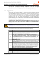
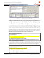
Clicking on the “configure” button opens up the following window:
Phocos AG
www.phocos.com
37
Subject to Change without notice
Hybrid Solar Power Fuel Cell Unit FC20/FC40
Description of the Visualisation and Parameterisation Software
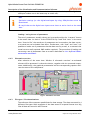
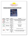
Fig. 16:
Event control for GSM module
In case of certain events the fuel cell unit offers the opportunity to submit a respective message to the user. For each individual event that can be activated in the
menu (1) it can be additionally determined whether it has to be transmitted by SMS
to a mobile phone, or by e-mail to a PC (or both) (2).
If for example the first entry in the menu is activated (“end of a charging cycle”), a
message in the following form will be submitted to the respective receiver as soon
as the charging process is finished. Each individual (sedecimal) number within a
message corresponds to certain measured values or states that have been detected
during the charging cycle. The procedure to convert this rather cryptic message in
plain text is the same as described under ‘History charging cycles’.
From: [email protected]
To: [email protected]
1805060911101805060917210600930b950b020c1c0c970b980bffffffff42080509ff06ad07ac05af
06fe33a7364400070000006b01000035000000
-----------------------------------------------------This message has been submitted to you by T-Mobile.
Please consider for your answer that only the first 160 signs of the subject line and of the
content of the message will be transmitted.
If the hydrogen accumulator (cylinder) is equipped with a manometric switch and
the second entry of the menu is activated, the receiver will receive a message with
the following content in the case that the manometric switch has been triggered:
From: [email protected]
To: [email protected]
Manometric switch on H2 cylinder has been triggered
-----------------------------------------------------This message has been submitted to you by T-Mobile.
Please consider for your answer that only the first 160 signs of the subject line and of the
content of the message will be transmitted.
Phocos AG
www.phocos.com
38
Subject to Change without notice
Hybrid Solar Power Fuel Cell Unit FC20/FC40
Description of the Visualisation and Parameterisation Software
In dependence of the set value of the manometric switch it can be determined how
long the hydrogen supply can still be maintained, and when the gas cylinder has to
be replaced by a full one at the latest.
When the voltage of the connected accumulator falls below the voltage level of the
basic device settings, the fuel cell unit automatically starts the stacks and the
charging process. That means that in case of a correct function the voltage level
can never be significantly lower than the set threshold value. If this case occurs
nevertheless it indicates a failure, which can probably not be remedied without repair. The corresponding message is as follows:
From: [email protected]
To: [email protected]
Accumulator voltage has dropped below critical value!
-----------------------------------------------------This message has been submitted to you by T-Mobile.
Please consider for your answer that only the first 160 signs of the subject line and of the
content of the message will be transmitted.
The fuel cell unit disposes of a built-in manometric switch fulfilling an important
safety function. If the hydrogen supply will not be replaced in time or if there is a
significant leakage in the system there is a risk that the stacks would be damaged
due to undersupply. Operation with insufficient hydrogen supply must be absolutely
avoided. The built-in manometric switch is triggered at a pressure that usually is
sufficiently above the risk zone for the stacks. If the device recognises the triggering of this switch during operation, immediately load-disconnection and shutdown
take place. If the corresponding entry in the menu (1) has been activated, the device sends the following message:
From: [email protected]
To: [email protected]
Manometric switch 'low pressure' has been triggered
-----------------------------------------------------This message has been submitted to you by T-Mobile.
Please consider for your answer that only the first 160 signs of the subject line and of the
content of the message will be transmitted.
Hint
If the above messages are sent by SMS to a mobile phone only the parts of the
example messages with yellow background will be displayed.
The blue-bordered area offers convenient and flexible possibilities for the user of
Phocos AG
www.phocos.com
39
Subject to Change without notice
Hybrid Solar Power Fuel Cell Unit FC20/FC40
Description of the Visualisation and Parameterisation Software
the FC20/FC40 to install remote control and survey functions corresponding to his
concrete problem, reaching well beyond the normal functions of a fuel cell unit.
In the first selection box (3) the object to be surveyed can be determined. Depending on whether a digital or an analog input has been chosen, a corresponding event
can be selected now (4). In case of an analog input (on which a voltage between 0 V
and 10 V can be applied) this event can be that the voltage falls below or exceeds a
voltage level defined in the next input field (5). For the first digital inputs, the corresponding event can be the detection of a “0” level or “1” level. Since these inputs are evaluated with the polling procedure, in the least favourable case a duration of 125 ms is required for the detection of the significant level.
Each previously defined event can be defined in the next selection field as condition for the submittal of a message. As already described for the system events, it
can be chosen between SMS, e-mail or both communication ways (6). If the choice
has been made to send a message in case of the next occurrence of the respective
event the content of the message can be formulated at will, and be entered into
the following input field (7).
Independent of whether a message has to be transmitted or not, the states of the
two available digital outputs can be event-dependently influenced. By respective
selection in the last field (8) the digital output 1 or 2 can be set to “0” level or to
“1” level in case of the occurrence of the related event. A possible variant is the
logical negation of the actual state.
By clicking the “OK” button (10) the chosen settings are transferred to the controller of the fuel cell unit. If the transfer is not desired the window can be closed by
clicking on the “abort” button (9).
For all events on the user-inputs the following applies:
If an event to be monitored by the controller did occur, the corresponding reactions
will be carried out only once. Therefore it is insignificant how long the event continues. But it also means that the new occurrence of the significant event (even after the previous event-relevant state has already ended) does not lead to a new reaction. In order to “arm” the event control anew, a special message must be sent
to the fuel cell unit or its GSM module, respectively (explanations in the respective
paragraph).
Hint
Reactions to USER events are carried out only once. The event control must be
reset explicitly by sending a special message.
Phocos AG
www.phocos.com
40
Subject to Change without notice
Hybrid Solar Power Fuel Cell Unit FC20/FC40
Description of the Visualisation and Parameterisation Software
The FC20/FC40 is not only capable to send messages but also to receive messages
and to react in the way described in the following. The special content of the SMS
or e-mail to be sent to the fuel cell unit has been summarised in a table:
Content of the SMS or e-mail
Action of the receiving fuel cell unit
7 xxxx yyyy
Change user PIN (xxxx – old valid PIN; yyyy – new
PIN)
10 xxxx
Reset the event control on the user-inputs. (Condition for a new recognition of an event)
11 xxxx
Set digital user-output 1 to “0“
12 xxxx
Set digital user-output 1 to “1“
13 xxxx
Negate digital user-output 1
14 xxxx
Set digital user-output 2 to “0“
15 xxxx
Set digital user-output 2 to “1“
16 xxxx
Negate digital user-output 2
18 xxxx
The logged data of the last executed or of the
present charging process will be sent by SMS to
the mobile phone designated in the fuel cell unit
19 xxxx
The logged data of the last executed or of the
present charging process will be sent by e-mail
to the e-mail address designated in the fuel cell
unit.
The format of the message in case of commands
18 and 19 corresponds to that which is used in
the comparable system event.
48xxxx
The basic device settings will be send by SMS to
the mobile phone designated in the fuel cell
unit.
49xxxx
The basic device settings will be send by e-mail
to the e-mail address designated in the fuel cell
unit.
Similar to the logging data for a charging cycle, commands 48 and 49 provide
sedecimal numbers, which cannot be understood by simply regarding them. Like in
the case of the charging cycle messages, the operating software of the fuel cell unit
offers the opportunity to convert these numbers in plain text format. For this purpose, in the corresponding fields of the basic settings window, the necessary
changes must be carried out.
6.4.8
Real-time clock
If the menu item ‘tools Æ clock’ is selected, the following window opens up (if no
modifications are entered, the window closes automatically after 2 minutes):
Phocos AG
www.phocos.com
41
Subject to Change without notice
Hybrid Solar Power Fuel Cell Unit FC20/FC40
Description of the Visualisation and Parameterisation Software
Fig. 17:
Configuration real-time clock
The fuel cell unit is equipped with a battery-buffered real-time clock, which is read
out when the window shown above is opened. In the fields for time (1) and date (2)
the actual time and date of the fuel cell unit are shown, provided that a FC20/FC40
is connected and that the communication functions.
In order to set the clock there are several possibilities. With the small arrows in the
left margin of each field the value can be changed in both directions.
Hint
Impossible entries such as the 13th month or the 25th hour will be refused for this
method of setting the clock. However, the date will not be checked with respect
to calendrical rules.
The easiest and safest way to set the fuel cell unit clock is to click on the “import”
button (3). So, the system time of the computer will be displayed in the input fields.
When the button “transfer to fuel cell unit” (5) is clicked, all values displayed in
the time and date fields will be transferred to the fuel cell unit and stored there.
In order to determine whether the setting process has been successfully carried out
the button “read” (4) can be used. If it is clicked, time and date of the fuel cell
unit are requested and displayed anew.
The elements (6) and (7) appear on opening the window only in the case that the
operating program has detected that the fuel cell unit is equipped with a GSM modPhocos AG
www.phocos.com
42
Subject to Change without notice
Hybrid Solar Power Fuel Cell Unit FC20/FC40
Description of the Visualisation and Parameterisation Software
ule. The GSM module contains (like any other mobile phone) a real-time clock. If
the fuel cell unit is disconnected from the accumulator for a longer period of time,
the GSM module loses the correct time and date values. With the button “transfer
to GSM module” this clock can be set, too, with the values displayed in the input
fields.
Hint
The content of the GSM module clock is insignificant of the functions and for the
contents of the messages.
The orange-bordered fields serve for the preset of on- and off-times of the GSM
module. The controller in the fuel cell unit switches the GSM module on and off according to the values entered here. If the GSM module is to be switched-on continuously, in the field “unit” for “inactive time” the option “none” must be selected (in the opposite case the procedure is analogous). If for both times (inactive
and active) in the field “unit” the option “none” is used, the inactivity of the GSM
module is prioritary; the module remains permanently switched-off.
With the “abort” button (8) the window can be closed.
Phocos AG
www.phocos.com
43
Subject to Change without notice
Hybrid Solar Power Fuel Cell Unit FC20/FC40
Maintenance Service and Repair by the Customer Service
7
Maintenance Service and Repair by the Customer Service
According to the general sales terms and conditions for the device supplied by the
manufacturer, a GUARANTEE is issued. If during the guarantee period malfunctions
or damages to the devise should occur for which according to the guarantee conditions a guarantee has been issued, the manufacturer will after previous examination repair or replace the faulty components.
The manufacturer is responsible for the device in its original configuration.
All interventions concerning the device, its structure, the software or the operating
cycle of the device shall only be carried out by the manufacturer or by his express
authorisation.
Attention
The stipulated environmental conditions must be kept to.
The manufacturer is not liable for damages due to improper or inappropriate use of
the device and for damages due to interventions in the device that are not requested explicitly by the present manual.
For all these reasons, our customers should always contact our customer service.
Phocos AG
www.phocos.com
44
Subject to Change without notice