1
Save This Manual
For Future Reference
MODEL NO.
11 3.244401
Serial
Number__
Model and serial
number may be found
at the right-hand
of the frame.
side
You should record both
model and serial number
in a safe place for
future use.
IO-INCH DIRECT
BAND SA W
CAUTION:
Read GENERAL
ADDITIONAL
DRIVE
and
" assembly
SAFETY
INSTRUCTIONS
e operating
carefully
= repair parts
Sold
Part No. 691 87
by SEARS,
ROEBUCK
AND
CO., Chicago,
IL. 60684
U.S.A.
Printed in U.S,A.
-
-
=L
.....
FULL ONE YEAR WARRANTY
ON CRAFTSMAN
BAND
=
SAW
if within one year from the date of purchase, this Craftsman Band Saw fails due to a defect in
material or workmanship, Sears will repair it, free of charge.
WARRANTY SERVICE iS AVAILABLE BY SIMPLY CONTACTING THE NEARESTSEARS
SERVICE CENTER/DEPARTMENT
THROUGHOUT
THE UNITED STATES.
This Warranty Applies Only While This Product Is In Use In The United
This warranty gives
from state to state.
you specific
SEARS,
ROEBUCK
legal rights, and you may also have other
AND
CO.,
698/731A.
Sears
general safety instructions
1, KNOW YOUR POWER TOOL
Read and understand the owner's manual and labels
affixed to the tool. Learn its application and limitations
as well as the specific potential hazards peculiar to this
tool.
2. GROUND
ALL TOOLS
This tool is equipped with an approved 3-conductor
cord and a 3-prong grounding type plug to fit the proper grounding type receptacle. The green conductor in
the cord is the grounding
wire. Never connect the
green wire to a live terminal.
3. KEEP GUARDS
-- in working
alignment,
4. REMOVE
tN PLACE
order,
ADJUSTING
and in proper
adjustment
and
KEYS AND WRENCHES
Form habit of checking to see that keys and adjusting
wrenches are removed from tool before turning it on.
5. KEEP WORK AREA CLEAN
Cluttered areas and benches invite accidents.
must not be slippery due to wax or sawdust.
6. AVOID
DANGEROUS
Floor
ENVIRONMENT
Don't use power tools in damp or wet locations or expose them to rain_ Keep work area well lighted. Provide adequate surrounding work space.
7, KEEP CHILDREN
All visitors should
area.
AWAY
be kept a safe distance
from
work
8. MAKE WORKSHOP
CHILD-PROOF
with padlocks, master switches, or by removing
starter keys.
9. DONq" FORCE TOOL
It will do the job better and safer at the rate for which
it was designed
10. USE RIGHT
TOOL
Don't force tool or attachment
designed for.
11. WEAR
PROPER
to do a job it was not
APPAREL
Do not wear loose clothing, gloves, neckties or jewelry
(rings, wristwatches)
to get caught in moving parts.
NONSLtP footwear is recommended.
Wear protective
hair covering to contain long hair. Roll long sleeves
above the elbow.
12. USE SAFETY GOGGLES (Head Protection)
Wear safety goggles Imust comlJly with ANSi Z87,1)
a_ alt times. "Everyday eyegfasses only have impact re-
Tower,
Chicago,
States.
rights which
vary
IL 60684
for power
tools
sistant lenses, they are NOT safety glasses." Also, use
face or dust mask if cutting operation is dusty, and ear
_Jrotectors (plugs or muffs) during extended periods of
operation.
13. SECURE WORK
Use clamps or a vise to hold work when practical. It's
safer than using your hand, frees both hands to operate tool.
14. DON'T OVERREACH
Keep proper footing and balance at all times.
15. MAINTAIN
TOOLS WiTH
CARE
Keep tools sharp and clean for best and safest
formance.
Follow
instructions
for lubricating
changing accessories.
16. DISCONNECT
TOOLS
before servicing; when changing
blades, bits, cutters, etc.
accessories
perand
such as
17. AVOID ACCIDENTAL
STARTING
Make sure switch is in "OFF" position before plugging
in.
18. USE RECOMMENDED
ACCESSORIES
Consult the owner's manual for recommended
accessories. Follow the instructions that accompany the accessories. The use of improper accessories may cause
hazards.
19. NEVER STAND ON TOOL
Serious injury could occur if the tool is tipped
cutting tool is accidentally
contacted.
or if the"
Do not store materials above or near the tool such that
it is necessary to stand on the tool to reach them.
20. CHECK DAMAGED
PARTS
Before further use of the tool, a guard or other part
that is damaged should be carefully checked to ensure
that it will operate properly
and perform its intended
function. Check for alignment
of moving parts, binding
of moving parts, breakage of parts, mounting, and any
other conditions that may affect its operation. A guard
or other part that is damaged
should be properly repaired or replaced.
21. DiRECTiON
OF FEED
Feed work into a blade or cutter against the direction
of rotation of the blade or cutter only.
22° NEVER LEAVE TOOL RUNNING
Turn power off. Don't _eave tool
complete stop,
UNATTENDED
until it comes to a
adamdonam safety
instructions
Safety is a combination of operator common sense and
alertness at all times when the band saw is being used.
h,
Safety
2. Getting
To Know
3. Basic
Band
4. Maintenance
5. Stabinity
Saw
instructions
Your
for Power
Operation
j.
k.
PAGE
Tools...
2
Band Saw ............
..................
...............................
16
18
Your band saw must be bolted securely to a stand or
work bench. In addition, if there is any tendency for
the band saw to tip over or move during certain operations such as cutting long heavy boards, bolt your
band saw stand or workbench to the floor.
m.
When cutting a large piece of material,
it is supported at table height,
for indoor use only.
7. Protection:
Eyes, Hands, Face, Ears, Body
a. Wear safety goggles that comply with ANSI
Z87.1 and a face shield if operation
is dusty.
Wear
ear plugs or muffs
during
extended
periods of operation.
Do not wear gloves..,
roll
long sleeves abo_e the elbow.
b. Do not cut pieces of material too small to hold by
hand.
Use caution when cutting off material
irregular in cross section which could
blade before the cut is completed.
A
molding for example must lay flat on the
not be permitted to rock while being cut.
When backing up the workpiece, the blade may
bind in the kerf (cut)...
this is usually caused by
sawdust clogging
up the kerf or because the
blade comes out of the guides. If this happens:
Turn off the band saw..,
remove plug
power source outlet..,
remove cover
band saw. Insert a screwdiver or wedge
kerf..,
rotate the wheels by hand while
ing up the workpiece.
,
e. Make sure the blade runs downward
toward the
table. Always adjust tracking wheel correctly so
that the blade does not run off the wheels.
from
from
in the
back-
n.
Never leave the band saw work area with the
power on, before the machine has come to a complete stop, or without removing
and storing the
switch key.
o.
Never operate band saw with cover removed.
q,
d. Never turn your band saw "ON" before clearing
the table of all Objects (tools, scraps of wood,
etc.) except for the workpiece and related feed or
support devices for the operation planned.
adjust blade tension
which is
pinch the
piece of
table and
p. Do not perform layout, assembly, or setup
on the table while the cutting toot is rotating.
c. Avoid awkward
hand positions where a sudden
slip could cause a hand to move into the blade.
Always
make sure
Do not feed the material too fast while cutting.
Only feed the material fast enough so that the
blade will cut. Keep fingers away from the blade.
I,
6. Location
f,
saw
Use caution when cutting off round material such
as dowel rods, or tubing. They have a tendency to
roll while being cut causing the blade to "bite".
Always use a "V" block, or clamp round material
to a miter guage.
17
of Machine.
This band saw is intended
band
i. Hold the work firmly against the table,
WARNING:
FOR YOUR OWN SAFETY,
DO NOT
ATTEMPT
TO OPERATE YOUR BAND SAW UNTIL
IT IS COMPLETELY
ASSEMBLED
AND INSTALLED ACCORDING
TO THE INSTRUCTIONS
... AND
UNTIL YOU READ AND UNDERSTAND
THE FOLLOWING:
3. General
for
work
Turn saw "off" and remove plug from power supply outlet before installing or removing an accessory or attachment.
Should any part of this band saw be missing, bend,
or fail in any way, or any electrical component
fail to
perform properly, shut off power switch and remove
plug from power supply outlet. Replace damaged,
missing, and/or failed parts before resuming operation.
correctly.
9. Think Safety.
Safety is a combination
of operator common sense
and alertness whenever the band saw is in operation.
g. ALWAYS adjust the upper blade guide and blade
guard to just clear the workpiece to protect the
operator, to keep blade breakage to a minimum,
and to provide maximum support for blade.
!0.
This band saw is not designed
WARNING:
DO NOT ALLOW FAMILIARITY
(GAINED
FROM FREQUENT
BECOME
COMMONPLACE.
ALWAYS
REMEMBER
THAT A CARELESS
SUFFICIENT
TO INFLICT SEVERE INJURY.
3
to cut meta!.
USE OF YOUR BAND SAW} TO
FRACTION
OF A SECOND iS
additional
safety instructions
for band saw
YOUR
The operation of any power tool can result in foreign
objects being thrown into the eyes, which can result in
severe eye damage. Always wear safety goggles complying with ANSI Z87.1 (shown on Package) before
commencing power tool operation. Safety Goggles are
available at Sears retail or catalog stores.
READ AND FOLLOW THE INSTRUCTIONS
THE FRONT OF THE BAND SAW.
APPEARING
_
DIRECT
ON THE INSTRUCTION
PLATE ON
DRIVE
SAW
--
-
---
=
iii
,
motor specifications
-
-
-
and electrica|
requirements
This machine
a 1725 RPM
volts, 60 Hz.,
CONVERTED
is designed to use, and is equipped with,
motor. It is wired for operation on 110-120
alternating current. (TOOL MUST NOT BE
TO OPERATE ON 230 VOLT).
For replacement motor refer to parts list in this manual;
CONNECTING
TO POWER
SUPPLY
This machine must be grounded
the operator from electric shock.
OUTLET
while in use to protect
Ptug power cord into a 110-120V properly grounded
type outlet protected
by a 15-amp.
dual element
time delay or Circuit-Saver
fuse or circuit
breaker.
If you are not sure that your outlet is properly
have it checked by a qualified electrician.
WARNING: IF NOT PROPERLY GROUNDED THIS
POWER TOOL CAN CAUSE AN ELECTRICAL
SHOCK PARTICULARLY WHEN USED IN DAMP
LOCATIONS CLOSE TO PLUMBING. IF AN ELECTRICAL SHOCK OCCURS THERE IS THE POTENTIAL OF A SECONDARY HAZARD SUCH AS
YOUR HANDS CONTACTING THE SAW BLADE.
if power cord is worn or cut, or damaged
have it replaced immediately.
Your unit is for use on 110.120
that looks like below.
volts, and has a plug
3-PRONG
PLUG
grounded,
WARNING: DO NOT PERMIT FINGERS TO TOUCH
THE TERMINALS OF PLUGS WHEN INSTALLING
OR REMOVING THE PLUG TO OR FROM THE
OUTLET.
in any way,
PROPERLY.
GROUNDED
3-PRONG OUTLET--_
GROUNDING
4
PRONG
and electrical
motor specifications
requirements
This power tool is equipped with a 3-conductor
cord
and grounding type plug which has a grounding prong,
approved by Underwriters'
Laboratories and the Canadian Standards Association.
The ground conductor has
a green jacket and is attached to the too! housing at
one end and to the ground prong in the attachment
plug at the other end.
This plug requires
outlet as shown.
a mating
3oconductor
grounded
GROUNDmNG
LUG
/
3-PRONG
_._
/
!...o J-,-.44---I
I_k-_-._j
II
¢t_n_Ts=n
MAKE
SURE THIS
T_ A_$
type
If the outlet you are planning to use for this power tool
is of the two prong type DO NOT REMOVE OR ALTER
THE GROUNDING
PRONG IN ANY MANNER. Use an
adapter as shown below
and always
connect
the
grounding lug to known ground.
It is recommended
that you have a qualified electrician
replace the TWO prong outlet with a properly grounded
THREE prong outlet.
A temporary
adapter as shown below is avaimable for
connecting
plugs to 2-prong receptacles.
The green
grounding
lug extending
from the adapter must be
connected
to a permanent
ground
such as to a
properly
grounded outlet box.
A temporary
adapter
as illustrated
is available
for
connecting
plugs
to 2-prong
receptacles.
The
temporary adapter should be used only until a properly
grounded
outlet
can be installed
by a qualified
electrician.
ADAPTER
AS TO A PROPERLY
NOT
ALL OUTLET
GROUNDED.
GROUNDED
OUTLET BOX.
BOXES
ARE
PROPERLY
If you are not sure that your outlet box is properly
grounded,
have it checked by a qualified
electrician.
NOTE:
already
The adapter illustrated
is for use only if you
have a properly grounded
2-prong receptacle.
The use of any extension cord wilt cause some loss of
power. To keep this to a minimum and to prevent overheating and motor burn-out, use the table below to determine the minimum wire size (A.W.G.) extension cord.
Use only 3 wire extension
cords which have 3-prong
grounding
type plugs and 3-pole receptacles
which
accept the plug on the saw.
Extension
WARNING:
THE GREEN
GROUNDING
LUG
EXTENDING
FROM
THE ADPATER
MUST
BE
CON N ECTED TO A PERMAN ENT GROUND
SUCH
Cord Length
Wire Size
Up to 100 Ft.
100 - 200 Ft.
200 - 400 Ft.
A.W.G,
16
14
10
CONTENTS
POWER
TOOL
WARRANTY
...................
GENERAL
SAFETY INSTRUCTIONS
POWER TOOLS
.............................
ADDITRONAL
FOR BAND
2
AND
CHECKING
3
ELECTRICAL
CONTENTS
4
...
6
ASSEMBLY
Mounting
Band Saw to Workbench
...........
Installing
the Table ...........................
Installing
the Blade
..........................
Tracking
the Blade ..........................
Adjusting
the Table Square to Blade .........
Guide Bar ........................
Adjusting
Adjusting
Front to Back Squareness
.........
Adjusting
Side to Side Squareness
..........
Adjusting
Upper Blade Guide Assembly
......
Adjusting
Upper Blade Guides ...............
Adjusting
Upper Thrust
Roller ...............
Adjusting
Lower Blade Guide Assembly
......
Adjusting
Adjusting
Adjusting
GETTING
SAFETY INSTRUCTIONS
SAW ............................
MOTOR
SPEC0FiCATJONS
AND
REQUIREMENTS
............................
UNPACKING
2
FOR
7
8
8
10
11
12
12
13
13
13
14
14
Lower Blade Guides ...............
Lower Thrust Roller ...............
Table .............................
TO KNOW
YOUR
BAND
14
15
15
SAW
Tension Adjustment
Knob ...................
Tension
Setting .............................
Guide Bar Lock Screw ......................
Thrust Roller Adjustment
...................
Table Lock Knob ............................
Tilt Scale ...................................
Blade Guides ...............................
On-Off
Switch ..............................
t 6
16
16
16
16
16
16
16
BASIC BAND SAW OPERATION
Sawing .....................................
Blade Selection Guide
......................
17
17
MAINTENANCE
.............................
Lubrication
.................................
18
18
RECOMMENDED
TROUBLESHOOTING
REPAIR
PARTS
ACCESSORIES
.......................
.............................
...........
18
19
20
unpacking
--
-
and checking
TOOLS
NEEDED
....
contents
_-- -_-
Model 113.244401
Band Saw is shipped complete
one carton but DOES NOT INCLUDE Steel Legs.
COMBINATION
MEDIUM
SQUARE
SCREWDRIVER
Separate all parts from packing materials and check
each item with illustration and "Table of Loose Parts".
Make certain all items are accounted for, before discarding any packing material.
{_8=:====
#2 PHILLIPS SCREWDRIVER
7/16 INCH WRENCH
3/8 INCH WRENCH
1/2 INCH WRENCH
5/! 6 INCH WRENCH
5/32 INCH SET SCREW
WRENCH
If any parts are missing, do not attempt to assemble the
band saw, plug in the power cord, or turn the switch on
until the missing parts are obtained and installed correctly.
COMBINATION
SQUARE
MUST
BE TRUE
STRAIGHT
EDGE OF
BOARD 3/4" THICK
THIS EDGE MUST BE
PERFECTLY STRAIGHT
DRAW LIGHT
LINE ON BOARD
ALONG THIS EDGE
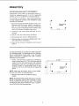
/
SHOULD
SQUARE
BE NO GAP OR OVERLAP HERE WHEN
IS FLIPPED OVER IN DOTTED POSITION
! ITEM
TABLE
OF LOOSE
PARTS
QTY.
i
/
¢
in
A
B
C
D
E
F
Basic saw assembly
...............
Owners Manual
...................
Saw Table ........................
Blade, Saw 1/4
.................
Insert, Table
......................
1
1
1
,.
1
1
Bag Assembly
Part - #691 32
Containing
the following
parts:
Roller, Blade Thrust
...............
Switch,
Key .......................
iNut, Wing 1/4-20
.................
Screw, Truss Hd. 1/4-20
x 1 .......
Washer 17/64
x 5/8 x 1/16
.......
Screw, Hex Hd. 5/16-18
x 3/4 .....
External Lockwasher,
5/16
........
2
1
1
1
1
2
2
Wrench,
1
Hex "L'" 5/32
............
assernbly
MOUNTING
BAND
SAW
TO WORKBENCH
If band saw is to be used in a permanent
location, it
should
be fastened
securely
to a firm supporting
surface such as a workbench
or accessory leg set,
If mounting
to a workbench,
through
supporting
surface
dimensions
illustrated.
!. Each foot
diameter
and 1/4"
length to
nuts, and
holes should be drilled
of the workbench
using
2. Locate and mark
mounted.
holes where
3. Drill (4) 11/32" din. holes through
4. Remove
T
should be bolted securely
using 1/4"
machine screws, washer, Iockwashers,
hex nuts. Bolts must be of sufficient
accommodate
legs of saw, washers, hex
thickness
of supporting
surface.
band
HOLES
12-1/8"--
_,
workbench.
band saw cover by releasing
screws,
[_.
9/32" DJA.(4)
saw is to be
latches.
5. Place band saw on workbench aligning
with holes drilled in workbench.
6. Insert all four
tighten.
5"
Iockwashers
holes in feet
and nuts and
An alternate method of mounting is to fasten band saw
to a mounting board. The board should be of sufficient
size to avoid tipping of saw while in use. Any good
grade of plywood or chipboard with a 3/4" minimum
thickness is recommended.
1. Follow instructions
for mounting
to workbench,
substituting
a board 1 8" x 24" minimum
size and
using 1/4 inch flat head screws, flat washers,
Iockwashers,
and hex nuts. Screws
must be of
sufficient
length
to accommodate
legs of saw,
washers,
hex nuts, and thickness
of supporting
board.
24" MIN.
18"
MIN.
5"
9/32"
HOLES
NOTE: Holes must be counter
sunk so screw
are flush with surface of supporting board.
2. Securely
clamps.
clamp board to workbench
heads
using C
NOTE: Supporting surface where band saw is mounted
should be examined carefully after mounting to insure
that no movement during use can result. If any tipping
or walking is noted, secure workbench,
legs, or supporting surface before operating band saw.
IDIA. (4)
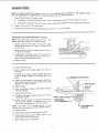
assembly
INSTALLING
THE TABLE
Applying a coat of automobile wax to the table
inside surfaces of trunnion
that slide on frame
and
will
ease sliding on these surfaces.
1.
|
2.
Locate two (2) 5/16 - 18 x 3/4 inch hex head screws
and external Ioc kwashers among loose parts.
3.
Position trunnion at the 0 degree position and tighten table lock knob.
4.
Place table on trunnion so that the slots in trunnion
line up with the mounting
holes in table as illustrated.
5.
Insert hex head screw and Iockwasher
through
front hole of trunnion )nto table and tig hten.
6.
Loosen table Lock Knob
the 45 degree position.
7.
Insert hex head screw and Iockwasher
hole of trunnion into table and tighten.
8.
Return table to the 0 degree
table lock knob.
INSTALLING
and position
Trunnion
through
position
WAX
_ SURFACES
_
F-'TRUNN'ON
\
_
--TABLE
__
_'_
LOCK KNOB
_--- EXTERNAL
___
LOCKWASH ER
5/16-18 HEX HEAD SCREW
rear
and tighten
and remove the
blade guard.
BAR LOCK
BLADE
--,
SCREW_
t11
1_-7--'--'_
MOUNTING
2. Loosen the guide bar lock screw and position the
upper guide assembly
abOVescrew,
the table
TABLE _F_
GUIDE
screws
--APPLY
____,_
at
THE BLADE
1. Loosen the two mounting
_
TO NSaDE
Loosen the guide bar lock screw and position the
upper guide assembly all of the way up. Tighten
lock screw.
approximately
as shown
and
two
tighten
inches
the
SCREWS_
! }
I
11!1_
_J_
_----_LI
l_lltl_----__._
__
__'_
Iock UPPER B L/_p,.Eo,
._,
____-_
Z_._
GUIDE ASSEMBLY
-"-_ _[;Z_- ._,':
"_-'_
_
GUIDE
BAR
assembly
HEX HEAD
SCREWS
3. Loosen the two cap screws that lock upper
guides and separate them about 1/8 ':
4. Find a Thrust Roller among
in upper guide assembly.
BLADE GUIDES--_
THRUST
blade
R© LLER ----_:_
loose parts and insert
5. Loosen two hex head screws in upper guide assembly and slide assembly all of the way back in the
slots.
6. Tighten
_..
CAP SO
hex head screws.
7. Loosen lock nut on thrust roller adjustment
screw.
©
8. Back out thrust roller adjustment screw by turning
counter clo(:kwise using 5/32 inch setscrew wrench.
©
______
THRUST
_____
ROLLER
ADJUSTMENT
L
_-LOCK
NUT
BLADE GL
9. Loosen the two capscrews
that lock the
blade guides and separate them about 1/8"
10. Find a Thrust Roller among
lower guide assembly.
lower
loose parts and insert in
""_'_
THRUST
ROLLER
CAP S
I
11. Loosen lock nut on thrust roller adjustment
12. Back out"thrust
roller adjustment
screw by turning
counter clockwise using 5/32 inch setscrew wrench.
!3.
Loosen inner and outer
assembly adjustment.
lock nuts on lower
14. Turn Iocknuts clockwise
and move
assembly back to the frame tube.
LOCK
screw.
lower
,=_'--_-]
::)]
NUT--
r-_THRUST
ROLLER
/ADJUSTMENT
SCREW
guide
guide
LOCK NUT
assembly
TENSION
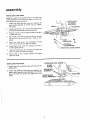
15. Carefully uncoil the blade holding it at arms length.
!6,
Place the blade over the wheels with the teeth
pointing downward
toward the table as shown.
Make sure the blade is in the center of the rubber
tires.
INDICAT__
_
WASHERJ
NOTE: Your band saw can be used with 1/4 or 3/8 inch
wide blades, 72 5/8 inches long. A 1/4 inch blade is
included with this saw.
17. Turn tension adjustment
knob clockwise until the
large washer lines up with the tension indicator on
the inside of the cover.
18. Turn the upper wheel by hand clockwise a few
turns and notice if the blade re mains in the approximate center of the tires.
If the blade moves away from the center of the
wheels while you are turning it, the blade is not
TRACKING properly.
DE
CENTERED
ON TIRES
OFBOTH
WHEELS
TRACKING
THE BLADE
The Motor Bracket is hinged which allows the upper
wheel to be tilted so that the blade can be TRACKED.
By turning the Tracking Adjustment
Screw, the upper
wheel will be tilted (see iliustration).
MOTOR
if the blade moves toward the front of the band saw:
a.
Turn the tracking
adjustment
screw
clockwise
about 1/4 of a turn, as though you were tightening
it.
TRACKING
ADJUSTMENT
SCREW ---,,
If the blade moves toward the back of the band saw:
a.
Turn the tracking adjustment
screw counter clockwise about 114 of a turn as though you were loosening it.
Turn the screw just enough to cause the blade to run in
the approximate center of both tires.
REAR
FRONT
10
assembly
NOTE: IF BLADE CANNOT BE MADE
MAY BE NECESSARY TO REPOSITION
i.
TO RUN IN THE APPROXIMATE
CENTER OF THE
THE UPPER WHEEL ON THE MOTOR SHAFT.
LOWER WHEEL,
tT
Loosen the set screw in the upper wheel.
a,
If the blade is running
b,
If the blade is running to the rear of lower wheel - Slide upper
2.
Tighten
3,
Track the blade by turning
ADJUSTING
to the front of lower wheel - Slide upper
wheel
whee!
to the rear toward the motor.
to the front away from the motor.
the set screw in the upper wheel.
THE TABLE
the tracking
SQUARE
adjustment
screw in or out as needed.
TO BLADE
NOTE: The combination
square must
start of "assembly"
section for checking
be "true".
method.
See
1. Loosen guide bar lock screw and raise the upper
blade guide assembly all the way up. Tighten guide
bar lock screw.
2. Place a square on the table against
the blade as illustrated.
the rear edge of
3. If adjustment is required, loosen the two screws
the trunnion
stop brackets and tap table up
down until table is square with blade.
4. Tighten
in
or
screws.
5. Loosen table lock knob.
6. Place a square on the table
illustrated,
against
the blade
as
7. Tilt table up or down to atign table 90 degrees to
blade (0 degree position} and tighten table lock
knob.
_-"
8. Loosen the two screws in the trunnion
stop brackets and slide bracket under lock knob until it rests
against end of slot in trunnion.
9. Tighten
COMBINATION
SQUARE
t______,
;I . --SAWBU,OE
screws.
10. Check squareness of blade to table, Make
ments if necessary.
readjust-
11. Loosen table lock knob.
12. Tilt table to 45 degree
combination square.
!3.
position and check
using a
Loosen the two screws in the trunnion stop brackets and slide bracket on opposite
side of lock
knob until it rests against end of slot in trunnion.
NOTE:
Be careful not to change position
of slide
bracket under lock knob that set the 0 degree position.
14. Tighten
STOP BRACKET
SCREWS
screws.
t5.
Check blade to table at the 45 degree
position.
!6.
Loosen table lock knob and position
gree position; recheck squareness.
table at 0 de-
17. Make readjustments
if necessary.
11
assembly
ADJUSTING
GUIDE
BAR
NOTE: When the upper guides are raised or lowered,
they must not deflect the blade front to back or sideways. This means that the guide bar must be parallel to
the blade.
1. Lower guide bar until it
inches above table. Tighten
is approximately
1-3/4
guide bar lock screw,
2. Hold a square on table against guide bar as shown
to check side to side squareness.
3. Hotd square on table against guide bar as shown to
check front to back squareness.
NOTE: Square must rest on the guide bar and not on
the upper guide bracket, Note illustration.
ADJUSTING
FRONT
TO BACK
SQUARENESS
NOTE: When
making
adjustments,
guide
bar lock
screw must be loosened. To check squareness it must
be tightened.
a.
b.
c.
GUIDE BAR _11
BRACKET
\"_J
ADJUSTMENT
\_
SCREWS
_-
Loosen guide bar lock screw and lower guide bar
until it rests on table. Leave lock screw loose,
Loosen two hex head screws on the top of frame
tube.
Loosen lock nuts on guide bar bracket adjustment
screws.
LOCKNUTS__
NOTE: Turning guide bar bracket adjustment
screws
clockwise will move quide bar toward front of saw.
Turning screws counter clockwise will move guide bar
to rear of saw.
d,
Turn guide bar bracket adjustment
turn using phillips screwdriver.
e,
Tighten
f.
Raise guide bar I-3/4
bar lock screw.
g.
hA
Check squareness.
Readjust if necessary,
Hold guide bar bracket adjustment
screws
phillips screwdriver
and tighten lock nuts.
hex head screws
screws
on top of frame
inches
and tighten
1/4
tube.
guide
with
12
_
.._--
HEX HEAD
7
SCREWS
FGUIDE
BAR
i
BRACKET
assembmy
ADJUSTBNG
S_DE TO $_DE
NOTE:
When
making
adjustments,
screw must be loosened. To check
be tightened.
a.
b.
c.
d.
e.
f.
!/y---
SQUARENESS
_
guide b_r iock
squareness it must
tP
Loosen guide bar lock screw
and lower g_Jide bar
until it rests on table. Leave lock screw loose,
Loosen two hex head screws
on top of frame tube.
Grasp guide bar as illustrated
and move to the side
needed to square it with
table. -[his wilt slide the
guide bar bracket into position.
Tighten hex head screws on the top of frame tube,
Raise guide bar 1-3/4 inches
and tighter_ _j_ide bar
lock screw.
Check squareness.
ADJUSTING
UPPER
Readjust
BLADE
HEX HEAD
SCREWS
_
_GUiDEBAR
i
_"
8RACKET
if necessary.
GUIDE
ASSEMBLY
G ULLET--_Z
NOTE: The upper and lower
blade guides support the
blade and keep it from twisting
during operation. An adjustment is necessary when
bRades are changed or replaced.
"Z
l
Z
1. Loosen two hex head screws
in upper blade guide
assembly and slide assembly
forward in the slots
until the front edge of the blade guides are approximately 1/32"from
the GULLET
of the saw blade.
2. Tighten
two hex head
_""-...-- B LAD E GUIDE
screws.
q
NOTE: It may be necessary
to back out thrust roller adjustment to allow thrust roller to move back from blade
to get 1/32" clearance from the gullet to edge of blade
guide.
!l
""_
SAW
ADJUSTING
UPPER BLADE
GUIDES
1. Loosen the two cap screws
that lock the upper
blade guides and press
the two guides evenly
against thesides
of the blade but do not pinch the
blade. ReJease the guides
and rotate the upper
wheel slightly clockwise
moving
the blade down,ward. Make sure one guide
is not further away
from the blade than the other. Tighten both cap
I'_'---APPROX,
1132
BLADE
CAP
SCREW
screws.
BLADE
GUBDE{
13
CAP
SCREW
assembly
ADJUSTING
NOTE:
rear
them
ting,
t
2,
UPPER THRUST
The
and
thrust
toilers
support
when
the
w_ll rotate
wh_le
you
the rotters
To
be sure
the
blade,
are cutting.
should
the
stop
turn
the
THRUST
b}ade
from
is pushed
soon
as you
the
stop
thrust
is properly
roller
supporting
adjustment
Whiie
turn_ng
hand,
adjust
blade
the
and
upper
wheel
roller until
to rotate.
it
clockwise
by
stops
LOWER
BLADE
rotating
while
upper
roller
adjust,
GUIDE
until
the
front
1/32"
edge
of the
from
the
lock
1. Loosen
blade
Z
_
1t32"
THRUST
"2_
ADJUSTMENT
the
ROLLER
blade
GULLET
°i
nuts,
LOWER
guides
rHRUST ROLLER
ADJUSTMENT
SCREW
GUIDE
SAW
ADJUSTING
NUT
APPROX.
_
NOTE: It may be necessary to back out thrust roller adlustment to allow thrust roller to move back from the
blade to get !132" clearance from the gullet to edge of
blade guide.
Tighten
BLADE
ASSEMBLY
Turn
Iock nuts
on lower
blade
guide
assembly
counter
clockw=se
and
move
lower
blade
guide
forward
LOCK
0
_---
guides
are app{oximately
of the _w bfade,
2.
/
it barely
touches
the
Now
move
the roller
T_gn[er,. lock nut while holding
thrust
ment screw with setscrew wrench.
assembly
/
}°
screw
roller
thrust
starts
/
rOtating,
roller
--7
cut-
5/32"
setscrew
wrench
so that the
towar(_ the blade and almost touches.
th_
ROLLER
against
using
moves
ADJUSTING
1.
the
blade
As
thrust
back shghtly
until
wheel is rotated.
3.
ROLLER
two
BLADE
cap
and
GUIDES
screws
press
the
that
two
lock
the
guides
lower
the s_des of the blade but do not pinch the
Release
the guides
and rotate
the upper
wheet
stightty
moving
the
blade
" I_
"
evenly
against
blade.
clockwise
_
BLADE
down-
ward.
Make
sure one guide
is not further
away
from the blade than the other,
Tighten
both cap
SCre_¢S.
14
_4"-" B LAD E
_
GUIDES
CAP SCREWS
assembty
ADJUSTING
t.
2,
LOWER
To
be sure
the
biade,
the
THRUST
thrust
turn
the
ROLLER
rotler
thrust
is properly
rol!er
adiustment
532"
setscrew
wrench
so that the
toward the blade and a!most touches,
roller
Whiie
turning
hand,
adjust
blade
the
and
back
wheei
si;ghtly
untii
is rotated,
thrust
starts
upper
wheel
roller unti!
to rotate.
it
stops
clockwise
rotating
Tighten
iock nut whi!e
ho!ding
thrust
ment screw with setscrew
wrench.
4,
Rotate
check
ADJUST|NG
3.
4.
5.
while
upper
roller
adjust-
the upper
wheei
a few times
by
the blade guides
and thrust rollers.
adiustments
2.
by
!!
_CREW
it barely
touches
the
Now
move
the roller
3,
I
screw
using
moves
the
THRUST
ROLLER
ADJUSTMENT
supporting
THRUST
hand and
Make re-
ROLLER
if necessary,
GUARD
TRUSS
HEAD
THE TABLE
Replace the blade guard on the upper guide assembly and tighten screws.
Locate the table insert and place it in the opening in
the tabte,
Locate a 1/4 - 20 x ! " truss head screw, a flat washer, and a 1/4 -. 20 wing nut among loose parts, insert screw into hoie in table top as illustrated.
From the underside of the table, install washer and
wing nut onto the truss head screw and tighten
finger tight. This wit! keep the table flat and in
alignment,
Replace the cover.
SCREW---_
!
HER
6, Blade
should
be
in approximate
_nsert.
7. If blade runs to one side, loosen
that mount
table to trunnion
and
ter blade
8. Tighten
t
in table
center
hex
shift
of
head
table
slot
in
screws
to cen-
insert.
screws,
t5
getting
to know
your
band saw
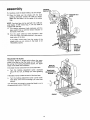
2
TENSSON SETTING
(gNSODE}
1
//----
TENSION
KNOB "-_
COVER RETAINING
CLIP (5 USED)
8
ON-OFF SWITCH
\
\
ADJUSTMENT
3
GUIDE BAR
LOCK SCREW
J
j_
\
F
BLADE GUARD
TABLE
-_
COVER
7
7
LOWER
BLADE
GUIDES
/
BLADE
GUIDES
6
TILT
SCALE
\
/
4
UPPER THRUST
ROLLER ADJUSTMENT
4
LOWER THRUST
ROLLER ADJUSTMENT
5
TABLE LOCK KNOB
FRONT
1.
TENSION
ADJUSTMENT
KNOB...Tightening
the knob will increase the tens=on on the blade,
Loosening it wilt decrease the tension.
2.
TENSION
SETTING...The
marking indicates the
correct blade tension for the blade. For example,
when installing the blade, tighten the tension adjustment knob until the indicator washer is pointing
to the marking on the inside of cover.
3.
BACK
GUIDE BAR LOCK SCREW...
The upper blade
guides should just clear the workpiece while cutting. Always adjust the upper guide assembly and
tock the guide bar by tightening the guide bar lock
screw before turning on the band saw.
ONOFF SWITCH
The On-Off Switch has a locking feature, THiS FEATURE IS iNTENDED TO PREVENT UNAUTHORIZED
AND POSSI8LY
HAZARDOUS
USE BY CHILDREN
AND OTHERS.
1,
THRUST
ROLLER
ADJUSTMENT...Turning
the adjustment screw moves the thrust roller in or
out to support the blade from the rear while cutting,
5.
TABLE LOCK KNOB ...Turning
the knob allows
the table to be tilted and locks it in place.
6.
TILT SCALE .,. Shows degree table is tilted,
7.
BLADE GUIDES.,.
Supports the blade and keeps
it from twisting during operation. An adjustment
is
necessary when blades are changed or replaced.
8,
ON-OFF
SWITCH...
See below and next page.
LLON
insert key into switch.
NOTE:
4.
Key is made of yellow plastic.
16
I
getting
2.
3.
To turnmachh_e
To
with
lock
OFF ..
LEAVE
IT HAS
THE
COME
switch
one hand
lever
'ew!}_
ir_.
MACHINE
UNATTENDED
TO A COMPLETE
STOP.
in OFF
.,,
PUSH
band
your
To turn machir_e on, insert finger under switch
arid pu4 e_d of switch out,
NEVER
UNTIL
4.
to know"
position.,,
REMOVE
key
hold
with
switch
other
ii'
IN
hand,
WARNING:
FOR YOUR OWN SAFETY, ALWAYS
LOCK THE SWITCH
"OFF"
WHEN
MACHINE
IS
NOT IN USE...
REMOVE KEY AND KEEP IT IN A
SAFE
PLACE...
ALSO...IN
THE EVENT
OF A
POWER FAILURE (ALL OF YOUR LIGHTS GO OUT)
TURN
SWITCH
OFF..,
REMOVE
THE KEY AND
STORE DTREMOTE FROM BAND SAW. THIS WILL
PREVENT
THE MACHINE
FROM STARTING
UP
AGAIN WHEN THE POWER COMES BACK ON.
basic
band saw
operation
A band saw is basically a "curve cutting" machine. It is also used for straight-line cutting operations such as crosscutting, ripping, mitering, beveling, compound cutting, and resawing, tt is not capable of doing inside curing.
This band saw is not designed
to cut metal.
SAWING
,
1.
Adjust the upper guide
workpiece.
2.
Use both hands while feeding the work into the
blade. Hold the workpiece firmly against the table.
Use gentle pressure, and do not force the work, but
allow the blade to cut.
BLADE SELECTION
MINIMUM
CIRCLE
assembly
The
smallest
to just clear the
approximately
GUIDE FOR
CUTTING
BLADE
SIZE
diameter
circle
that
can
determined
by the width
of the blade.
a 1/4" wide blade will cut a minimum
3,!8 ,,
114"
t7
1-1/2 £ (See
Chart)
be cut
out
is
For example,
diameter
of
maintenance
WARNING:
FOR
YOUR
OWN
SAFETY.
SWITCH
"OFF"
AND
REMOVE
PLUG
POWER
OUTLET
BEFORE
MAINTAINING
LUBRICATING
YOUR BAND SAW.
TURN
FROM
OR
BLACK
TIRES
Pitch
be
and
sawdust
removed
with
piece of wood.
solvent,
When
_%'hen
wheels
the
that
accumulate
a stiff
brush
Do not
t_res become
on the
tires
or scraped
off
use a sharp
worn
replacing
the tires,
but do not g_ue them
knife
they
should
stretch
on.
them
should
with
a
or any kind
of
be replaced.
around
MOTOR
the
GENERAL
Keep your Band Saw clean.
Remove sawdust
Do not
altow
sert. blade
Craftsman
Apply
pitch
from the inside.
to accumulate
on the table,
guides,
or thrust
rollers.
Gum and Pitch Remover.
a thin
coat
of automobile-type
so tt_e wood slides easily while cutting.
to the _nside surfaces
of the trunnion.
Clean
wax
blade
them
on
Also
in-
with
the table
apply
wax
MOTOR
Frequently
motor,
vacuum
or blow
out
any
sawdust
If the power cord is worn, cut, or damaged
have it replaced immediately.
from
the
in any way,
LUBRICATION
All of the BALL BEARINGS are packed with grease at
the factory. They require no further lubrication.
RECOMMENDED
ACCESSORIES
Item
Cat. No.
Floor Stand ...............................
Miter Gauge ..............................
Rip Fence ................................
Blades ................................
Steel Leg Set ...........................
Circle Cutting Attachment ...................
Table Extension ...........................
Power Tool Know How Handbooks
Radial Saw ................................
Table Saw .................................
9-2221 3
9-29929
9-23433
See Catalog
9-22244
9-24301
9-24302
9-2917
9-2918
The above recommended
accessories are current
and were available at the time this manual
was
printed.
18
troubleshooting
WARNING:
SOURCE
FOR
OUTLET
YOUR
OWN
SAFETY,
TURN
BEFORE
TROUBLESHOOTING
TROUBLE
Motor
will
not
PROBABLE
run,
I.
2,
Defective
Defective
SWITCH
YOU_
"OFF"
AND
BAND
SAW.
REMOVE
CAUSE
OnOff
switch
Defective
switch
Motor Defective,
PLUG
FROM
POWER
REMEDY
switch.
cord.
t,
Replace defective
Band Saw again,
2.
Consut[
parts
before
using
box receptacle.
Sears
Service.
Any
attempt,
to repair
this motor may create a HAZARD
unJess
repair is done by a qualified
serv}ce techniciar'.
Repair
Store,
Blade
does
not
approximate
upper
wheel,
Blade
does
not
approximate
lower
wheel.
Band
Saw
when
cutting.
Blades
run
center
breaking.
1, Not
tracking
properly.
at your
nearest
Sectior_,
Upper wheel not positioned
correctly
on shaft.
1, Reposition tile wheel, see Assembly
Section, "Tracking the Blade."
1,
Cutting
1. Stop feeding,
slightly,
until
2.
Dull blade.
of the
down
is available
1. Adjust tracking,
see Assembly
"Tracking
the Blade."
of the
run in the
center
s_ows
in the
service
too small
1. Too much
2.
Kink
a radius.
2.
tension,
in blade caused
too small
material
1. Adjust
by cutting
a radkJs or turning
too fast when
Replace
the
cutting.
19
2.
and back up to the material
the band saw speeds up.
blade.
tension.
See Getting
To Know
Your Band Saw "Tension
Setting".
Use correct cutting
technique.
See Basic
Band Saw
Operation
Section.
Sears
CRAFTSMAN
10-INCH
BAND
SAW,
MODEL
113.244401
18
16
\
14
\
o
/
1_,
11
12
13
/
12
46
40
41
\
\
/
3
45
44
42
FIGURE
1
I
CRAFTSMAN
10-INCH
Always
BAND
order by Part Number
FIGURE
PART
NO.
KEY
NO.
I'O
1
2
3
4
5
6
7
8
9
10
1!
12
!3
!4
15
16
17
!8
19
20
2!
22
23
24
25
69031
60386
60430
69109
STD600603
63467
69118
60256
62442
69119
STD375006
STD601103
STD 55121
60289
69123
69128
69127
60419
60321
60432
!60323
STD551025
STD54t625
69129
69133
"Standard
Hardware
x 3/64
*Spring, Tension
*Screw,
Pan Cross Type T6-32
Cap-Flag Terminal
Cover, Switch
Key, Switch
Switch
Cord
*Connector,
Wire
*Screw,
Pan Rec Type T 10-32
*Lockwasher,
Ext. NIO
Ring, Hog
Cord with Plug
Seal, Motor Foam
Cover, Motor
Screw, Pan Hd. Plastite
Screw, Thumb 5/16-18
x 3/8
1 PARTS
26
27
28
29
30
31
32
33
34
35
x 3/8
8-16 x 1/2
x 1-1/2
Spacer, 7/16
ID x 1800
Screw, Truss Hd. 1/4-20x
1
*Washer,
17/64 x 5/8 x 1/16
*Nut, Wing 1/4-20
Table
Table Insert
Item -
-
KEY
NO.
NAME
Knob Asm, Tension
Washer,
15/32 x 1-3/8
Washer .47 x 2.5 x .06
SAW,
36
37
38
39
40
41
42
43
44
45
46
47
MODEL
113.244401
not by Key Number
LIST
PART
NO.
69120
69121
60076
63387
109751
STD551031
STD541110
STD551131
STD523107
60431
69084
139377
STD541031
273229
69110
18232
193250
69114
69112
69115
69126
STD551008
69187
69132
NAME
Trunnion
Guide, Trunnion
Washer,
.505 x 7/8
Knob
x t/16
Bolt, Carriage 5/16-18
x 2-3/4
*Washer,
21/64 x 7/8 x 1/8
*Nut, Hex 10-32
*Lockwasher,
5/16
*Screw, Hex Hd. 5/16-18 x 3/4
Screw, Soc Cap 10-32 x 2-1/2
Foot, Frame
Screw, Hex Soc Set 5/16-18-1
Nut, Hex 5/16-!8
Screw, Hex Type T 1/4-20
x 1/2
Bar, Guide
Roller, Blade Thrust
Screw, Hex Soc Cap 10-32 x 7/8
Guide, Blade
Bracket Asm, Upper
Guard, Blade
Cover Asm., Front
*Washer,
3/16 x 3/8 x 1/16
Owners Manual (Not Illustrated)
Bag Of Loose Parts (Not Illustrated)
May Be Purchased Locally.
tStock item -- May be secured through the Hardware
Order Houses.
Department
of most Sears or Simpsons-Sears
Retail Stores or Catalog
CRAFTSMAN
10-iNCH
BAND
SAW,
MODEL
113.244401
2O
i
43 i--,--_
FIGURE
2
oANY ATTEMPT TO REPAIR THIS
MOTOR MAY CREATE A HAZARD UNLESS REPAIR IS DONE
BY A QUALIFIED
SERVICE
TECHNICIAN.
REPAIR SERVICE
IS AVAILABLE AT YOUR NEAREST SEARS STORE,
CRAFTSMAN
10-iNCH
FIGURE
KEY I
PART
I'J
8
9
10
11
12
13
t4
15
16
SAW,
2 PARTS
113,244401
LIST
PART
NO.
23
24
25
26
814584
69111
STD5411!0
9416390
27 i STD541025
28 1 69142
291 60433
30 I STD315228
31 I 41812
32 I 41815
33 I 69028
34 I 69130
35 I 18232
36 I 139377
37 I STD541031
38 I 69105
Tire
*Key, Square 3/16
x 15/16
*Screw,
Hex Soc 5/16-18
x 5/8
Wheel, Drive
*Nut, Hex 8-32
*Lockwasher,
Ext. N8
Motor Mount Assembly
STD503105
69116
!STD541008
STD551208
69106
MODEL
KEY
NO.
NAME
NO. I
NO.
t
69117
4
5
6
7
BAND
STD581050
69108
69137
69107
STD581062
102584
STD541425
109129
273229
*Ring, Retaining
Bracket, Guide
®Motor
Rod, Guide
17
69124
18
STD551010
Cover, Rear
*Washer, 13/64 x 7/16 x 1/16
391 193250
40 STD551210
_Screw, Pan Rec. Type T 10-32 x 1/2
41
69114
42
43
69113
37837
19
STD601105
20
2!
22
69125
60525
37838
*Ring, Retaining
5/8
Screw, Set Hex Cup 5/16-18
Lock Nut, 1/4-20
x 3/4
Bolt, Carriage 7/16-14
x 3
Screw, Hex Type T 1/4-20
x 1/2
Latch
_rRing, Retaining
5/8
Washer,.629
x 7/8 x 1/64
*Standard
tStock
1/2
Rod
Hardware
Item -
part
is removed,
Screw, Spl. Hex Hd. 1/4-20
Bracket, Guide Bar
*Nut, Hex 10-32
Department
discard
and replace
with
Spacer
*Bal! Bearing
Ring, Retaining
Tire
Wheel, idler
tBlade, Band Saw 1/4 x 72-5/8
Roller, Blade Thrust
Screw, Hex Soc Set 5/16-18
x 1
Nut, Hex 5/16-18
Frame Assembly
Screw, Hex Soc Cap 10-32 x 7/8
*Lockwasher,
Ring,
Int. N10
Guide, Blade
Bracket Asm., Lower
!-Wrench,
Hex "L" 5/32
of most Sears Retail Stores or Catalog
a new Retaining
x 3-1/4
Screw, Pan Cross Type "'T'" 10-32
Nut, Hex 1/4-20
Shaft, Wheel (Includes
Key 2!)
May Be Purchased Locally,
Item -- May be secured through the Hardware
Order Houses.
_-If this
NAME
x 5/8
SERVICE
10-1NCH
NO SAW
Now
your
that you
should
ply
contact
any
for repair parts
Service
number
ORDERING
FOLLOWING
of your
lO-Inch
Center
not
service,
sim-
and
most
Sears,
all pertinent
will
be
saw.
GIVE THE
DESCRIPTION
NAME
OF
lO-Jnch
may be ordered
and most
stocked
Saw
ALWAYS
PART
NUMBER
listed
transmitted
Band
side of the
REPAIR PARTS,
113.244401
parts
Saw
INFORMATION:
MODEL
All
or
Band
Be sure to provide
PART NUMBER
HOW
TO ORDER
REPAIR
PARTS
Center
on a plate at the right-hand
WHEN
l O-inch
you call or visit.
model
found
Sears
and Co. stores.
facts when
The
purchased
a need ever exist
Roebuck
M ODEL NO.
1 1 3.244401
have
Sears stores.
locally,
to a Sears
your
Band
Saw
from
any
Sears
Service
If the
parts
you
need are
order
Repair
ITEM
wil
Parts
be
electronically
Distribution
Center
for handling.
Sold
Part
No.
69187
by SEARS,
ROEBUCK
AND
CO., Chicago,
Form No SP501 !-t
IL. 60684
U.S.A.
Printed
in U.S.A.
10/86