1
Save this Manual
for Future Reference
Sears !
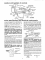
MODEL NO,
113.207600
SAW ONLY
MODEL NO.
113.207650
SAW WITH
LEGS
Serial
Number
Model
and
serial
number may be found
at the right-hand
of the base
side
You should record both
model and serial number
in a safe place for
future use,,
18=iNCH
SCROLL
CAUTION:
Read GENERAL
and ADDITIONAL
SAFETY
® assembly
H_STRUCT_ONS
o operating
carefully
Sold by SEARS,
Part No
66017
MO TORIZED
SA W
o repair parts
ROEBUCK
AND
CO.,
Chicago,
iL
601384
U.S.A.
Printed
in USA,
FULL
ONE YEAR WARRANTY
ON CRAFTSMAN
SCROLL
SAW
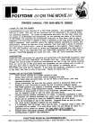
If within one year from the date of purchase, this Craftsman Scroll Saw fails due to a defect
in material or workmanship, Sears will repair it, free of charge+
WARRANTY SERVICE IS AVAILABLE BY SIMPLY CONTACTING THE NEAREST SEARS
SERVICE CENTER/DEPARTMENT
THROUGHOUT
THE UNITED STATES
This warranty
applies only while this product
is in use in the United States
This warranty gives you specific legal rights, and you may also have other rights which vary
from state to state
SEARS, ROEBUCK
general
AND CO+, 698/731A, Sears Tower, Chicago,
safety
instructions
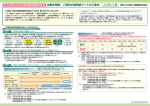
1+ KNOW YOUR POWER TOOL
Read and understand the owner's manual and labels
affixed to the tool Learn its application and limitations
as welf as the specific potential hazards peculiar to this
tool+
2,, GROUND
ALL TOOLS
This tool is equipped with an approved 3-conductor
cord and a 3+prong grounding type plug to fit the pro+
per grounding type receptacle. Tile green conductor in
the cord is the grounding wire, Never connect the
green wire to a live terminal.
3+ KEEP GUARDS IN PLACE
- in working order, and in proper adjustment
alignment.
4+ REMOVE
ADJUSTING
KEYS AND
and
WRENCHES
Form a habit of,checking to see that keys and adjusting
wrenches are removed from tool before turning it on.
5. KEEP WORK AREA CLEAN
Cluttered areas and benches invite accidents
must not be slippery due to wax or sawdust.
+
AVOID DANGEROUS ENVIRONMENT
Don't use power tools in damp or wet locations or expose them to rain_ Keep work area well
vide adequate surrounding work space+
7+
+
94
Floor
KEEP CHILDREN
AWAY
All visitors
alea+
be kept a safe distance
should
MAKE WORKSHOP
KID+PROOF
-- with padlocks,
master switches,
starter keys
lighted.
from
Pro-
work
or by removing
DON'T FORCE TOOL
It will do the job better and safer at the rate for which
it was designed+
10+ USE RIGHT TOOL
Don't force tool or attachment to do a job it was not
designed for,
11+ WEAR
PROPER
APPAREL
Do not wear loose clothing, gloves, neckties or jewelry
(rings, wristwatches)
to get caught in moving parts+
NONSLtP footwear is recommended, Wear protective
hair covering to contain tong hair, Roll long sleeves
above the elbow..
12+ USE SAFETY
GOGGLES
(Head Protection)
Wear safety goggles (must comply with ANSi Z87+1)
at all times "Everyday eyeglasses only have impact re+
IL 60684
for power
tooms
sistant lenses, they are NOT safety glasses." Also, use
face or dust mask if cutting operation is dusty, and ear
protectors (plugs or muffs) during extended periods of
operation+
13+ SECURE WORK
Use clamps or a vise to hold work when practical tt's
safer than using your hands and frees both hands to
operate tool
14+ DON'T OVERREACH
Keep proper footing and balance at all times+
15_ MAINTAIN TOOLS WITH CARE
Keep tools sharp and clean for best and safest performance. Follow instructions for lubricating and
changing accessories+
16. DISCONNECT TOOLS
before servicing; when changing accessories such as
blades, bits, cutters, etc
17+ AVOID ACCIDENTAL STARTING
Make sure switch is in"OFF" position before plugging
in power cord,,
18. USE RECOMMENDED ACCESSORIES
Consult the owner's manual for recommended acces+
sories+ FoIIow the instructions that accompany the accessories The use of improper accessoriesmay cause
hazards,
19. NEVER STAND ON TOOL
Serious injury could occur if the tool is tipped
cutting tool is accidentally contacted,,
or if the
Do not store materials above or near the tool such that
it is necessary to stand on the tool to reach them.
20_ CHECK DAMAGED
PARTS
Before further use of the tool, a guard or other part
that is damaged should be carefully checked to ensure
that it will operate properly and perform its intended
function+ Check for alignment of moving parts, binding
of moving parts, breakage of parts, mounting, and any
other conditions that may affect its operation. A guard
or other part that is damaged should be properly repaired or replaced.
21. DIRECTION
OF FEED
Feed work into a blade or cutter against
of rotation of the blade or cutter only_
the direction
22+ NEVER LEAVE TOOL RUNNING
UNATTENDED
Turn power off. Don't leave tool until it comes to a
complete stop+
additional safety instructions
Safety is a combination of operator common sense
and alertness at all times when the scroll saw is
being used
WARNING: FOR YOUR OWN SAFETY, DO NOT
ATTEMPT TO OPERATE YOUR SCROLL SAW
UNTIL IS IS COMPLETELY ASSEMBLED AND
INSTALLED
ACCORDING
TO THE INSTRUCTIONS
o . . AND UNTIL
YOU READ AND
UNDERSTAND THE FOLLOWING:
PAGE
1. General Safety Instructions for Power Tools
2
2_ Getting To Know Your Scroll Saw ........
15
3_ Basic Scroll Saw Operation ...................
17
4. Maintenance
...................................
18
& Stability of Machine.
Your scroll saw must be bolted securely to a stand
or work bench, In addition,
if there is any
tendency for the scroll saw to move during
certain operations, bolt your scroil saw stand or
workbench to the floor
6. Location
This scroll saw is intended for indoor use only
7. Protection: Eyes, Hands, Face, Ears, Body
a, Wear safety goggles that comply with ANSI
Z87,1 and a face shield if operation is dusty,
Wear ear plugs or muffs during extended
periods of operation Do not wear gloves ....
roll tong sleeves above the elbow
b Do not cut pieces of material too small to hold
by hand,,
c Avoid awkward
hand positions
where a
sudden slip could cause a hand to move into
the blade
d Never turn your scroll saw "ON" before
clearing the table of alf objects (tools, scraps
of wood, etc ,) except for the workpiece and
related feed or support
devices for the
operation planned,
e Make sure the blade teeth point downward
toward the table
f Always adjust blade tension correctly
g ALWAYS adjust the blade guard to just
contact the workpiece to protect the operator,
and
to provide
maximum
support
of
workpiece
h When cutting a large piece of material, make
sure it is supported at table height
i Hold the work firmly against the table
j, Do not feed the materiat too fast white cutting
Only feed the material fast enough so that the
blade win cu[ Keep fingers away from the
blade
k Use caution when cutting off material which is
irregular in cross sectfon which could pinch
the blade before the cut is completed A piece
of molding for example must lay fiat on the
tabte and not be permitted to rock while being
cut
I Use caution when cutting off round material
such as dowel rods, or tubing They have a
tendency to rotl while being cut causing the
blade to "bite" Always use a "V" block, or
clamp round material to a miter gauge
for scroln saw
m When backing the blade out of the workpiece,
the blade may bind in the kerf (cut)
this is
usuaNy caused by sawdust clogging up the
kerr If this happens: Turn off the scroll saw
remove plug from power source outlet
wedge open the kerr
back the blade out oi
the workpiece
n Never leave the scroll saw work area with the
power on, before the machine has come to a
complete
stop, or without
removing and
storing the switch key.
p Do not perform layout, assembly, or setup
work on the table while the cutting tool is
operating
q Turn saw "OFF" and remove plug from power
supply outlet before installing or removing an
accessory or attachment
& Should any part of this scroN saw be missing,
bent, or fail in any way, or any electrical
component
fail to perform properly, shut off
power switch and remove plug from power
supply outlet Reptace damaged, missing, and/or
failed parts before resuming operation
9. Think Safety.
Safety is a combination
of operator common
sense and alertness whenever the scroll saw is in
operation
WEAR
YOUR
The operation of any power too! can result in foreign
objects being thrown into the eyes, which can result
in severe eye damage Always wear safety goggles
complying
with ANSI Z87,1 (shown on Package)
before commencing
power tool operation
Safety
goggles are available at Sears retail or catalog
stores
WARNING: ALWAYS KEEP ALERT° DO NOT ALLOW FAMILIARITY (GAINED FROM FREQUENT USE OF
YOUR SCROLL SAW) TO CAUSE A CARELESS MISTAKE. ALWAYS REMEMBER THAT A CARELESS
FRACTION OF A SECOND IS SUFFICIENT TO INFLICT SEVERE INJtJRY.
3
location and function
TENSION
ON/OFF
SWITCH
of controls
KNOB
GUARD
LOCK
KNOBS
BLADE
HOLDER
RETAINING
CLIPS
GUARD
BLOWER
TUBE
]OLDERS
BLADE
HOLDER
POCKETS
BEVEL
SCALES
TABLE
INSERT
BEVEL
LOCK KNOB
BLADE
I
MITER
LOCK
GAUGE
KNOB
STORAGE
motor specifications and electrical requirements
This machine is equipped with a 1725 RPM motor it
is wired for operation on 110-t20 volts, 60 Hz.,
alternating
current.
(TOOL
MUST
NOT BE
CONVERTED TO OPERATE ON 230 VOLT)
For replacement motor refer to parts list in this
manual.
CONNECTING
TO POWER SUPPLY OUTLET
If power cord is worn or' cut, or damaged in any way,
have it replaced immediately
WARNING: IF NOT PROPERLY GROUNDED THIS
POWER TOOL CAN CAUSE AN ELECTRICAL
SHOCK PARTICULARLY WHEN USED IN DAMP
LOCATIONS
CLOSE TO PLUMBING.
IF AN
ELECTRICAL SHOCK OCCURS THERE IS THE
POTENTIAL OF A SECONDARY HAZARD SUCH
AS YOUR HANDS
CONTACTING
THE SAW
BLADE,
If you are not sure that your outlet, as pictured
below, is properly grounded, have it checked by a
qualified efectrician
Your unit is for use on 110-120volts, and hasa plug
that looks like illustration below
This power tool is equipped with a 3=conductor cord
and grounding type plug which has been approved
by Underwriters'
Laboratories
and the Canadian
Standards Association.. The ground conductor' has a
green jacket and is attached to the tool housing at
one end and to the ground prong in the attachment
plug at the other' end
WARNING:
DO NOT PERMIT
FINGERS
TO
TOUCH THE TERMINALS
OF PLUGS WHEN
INSTALLING OR REMOVING THE PLUG TO OR
FROM THE OUTLET.
3-PRONG
PLUG
PROPERLY
GROUNDED
OUTLET
GROUNDING
PRONG
Plug power cord intoa 110-120Vproperlygrounded
type outlet protected by a 15-amp dual element
time delay or Circuit-Saver fuse or circuit breaker
If the outlet you are planning to use for tMs power
tool is of the 2 prong type, DO NOT REMOVE OR
ALTER
THE GROUNDING
PRONG
tN ANY
MANNER
Use an adapter as shown below and
always connect the grounding lug to known ground
It is recommended
that you have a qualified
electrician replace the TWO prong outlet with a
properly grounded THREE prong outlet
GROUNDING
LUG
ADAPTER
3-PRONG
PLUG
MAKE SURE THIS IS
TO A
KNOWN GROUND
2*PRONG
RECEPTACLE
An adapter as illustrated is available for connecting
plugs to 2-prong receptacles
WARNING:
THE GREEN
GROUNDING
LUG
EXTENDING
FROM THE ADAPTER
MUST BE
CONNECTED
TO A PERMANENT
GROUND
SUCH AS TO A PROPERLY GROUNDED OUTLET
BOX. NOT ALL OUTLET BOXES ARE PROPERLY
GROUNDED.
If you are not sure that your outlet box is properly
grounded, have it checked by a qualified electrician
NOTE: The adapter illustrated is for use only if you
already
have a properly
grounded
2-prong
receptacle. Adapter is not allowed in Canada by the
Canadian Electrical Code
The use of any extension cord will cause some loss
of power. To keep this to a minimum and to prevent
over-heating and motor burn-out, use the following
table to determine the minimum wire size (AWG)
extension cord
Use only 3 wire extension cords which have 3-prong
grounding type plugs and 3-pole receptacles which
accept the tools plug
Extension Cord Length
0-25 ft.
26-50 ft.
51-100 ft,
Wire Size AWG
16
14
12
contents
POWER TOOL WARRANTY
...................
2
GENERAL SAFETY INSTRUCTIONS
FOR POWER TOOLS
...........................
2
ADDITIONAL
SAFETY INSTRUCTIONS
FOR SCROLL SAW ..............................
3
MOTOR SPECIFICATIONS
AND
ELECTRICAL REQUIREMENTS
4
...............
UNPACKING AND CHECKING CONTENTS
,,
ASSEMBLY
Assembling Steel Legs ........................
Mounting Scroll Saw on Leg Set .............
Mounting Scroll Saw to Workbench
...........
Mounting Scroll Saw to Mounting Board ....
Adjusting Guard ...........................
Installing Miter Lock Knob
.....................
Blade Installation and Tensioning
for Plain-End and Pin Type Blades ..........
To Install/Tension
Plain End Blades ........
Adjusting Insert To Table ................
To Install/Tension
Pin Type Blades ..........
To Remove Plain-End or Pin Type Blades.,
Adjusting the Blade Square to Table ........
Installation of Bevel Scales ................
unpacking
5
6
7
7
8
8
8
9
9
t0
tl
11
13
14
15
15
15
15
15
15
15
15
15
15
!5
15
15
16
17
17
18
18
18
19
19
20
and checking contents
TOOLS
_1
GETTING TO KNOW YOUR SCROLL SAW
Tension Control Knob
..................
Guard Lock Knobs ...............................
Guard ......................................
Blower Tube ..................................
Blade Holder Retaining Clips .............
Blade Holders
................................
Blade Holder Pockets .......................
Miter Gauge Lock Knob ...................
Table Insert ................................
Blade Storage ...................................
Bevel Lock Knob ...............................
Bevel Scales ..................................
On-Off Switch ..................................
Blade Storage
..................................
BASIC SCROLL SAW OPERATION
Sawing/Scrolling
.............................
Bevel Setting/Cutting
.........................
Use of Miter Gauge-Crosscutting
..........
Use of Miter Gauge-Ripping
...............
MAINTENANCE
..................................
RECOMMENDED
ACCESSORIES
...............
TROUBLESHOOTING
.......................
REPAIR PARTS ................................
COMBINATION
NEEDED
SQUARE
7/16" WRENCH
MEDIUM
3/4" WRENCH
Model 113 207600 Scroll Saw is shipped complete in
one carton but DOES NOT INCLUDE Steel Legs
Model 113,,207650 Scroll Saw is shipped complete in
one carton and INCLUDES Steel Legs
Separate all parts from packing materials and check
each item with illustration
and "Table of Loose
Parts", Make certain all items are accounted for
before discarding any packing material
If any parts are missing, do not attempt to assemble
the Scroll Saw, plug in the power cord, or turn the
switch on until the missing parts are obtained and
installed correctly
Wipe the base with a clean, dry cloth
WARNING:
FOR YOUR OWN SAFETY, NEVER
CONNECT PLUG TO POWER SOURCE OUTLET
UNTIL ALL ASSEMBLY STEPS ARE COMPLETE,
AND YOU HAVE READ AND UNDERSTAND THE
SAFETY AND OPERATIONAL
INSTRUCTIONS,.
1
5
2
3
COMBINATION
DRAW LIGHT
LINE ON 8CARD
ALONG THIS EDGE
SCREWDRIVER
SQUARE
MUST
BE TRUE
_.
A
_'"
STRAtGHT
EDGE OF
BOARD 314' THICK
BE
PERFECTLY
STRAIGHT
SHOULD
BE NO GAP OR OVERLAP HERE WHEN
SQUARE IS FLIPPED OVER IN DOTTED POSITION
Item
1
_2
3
4
5
Table 0f Loose Parts
Qty.
Scroll Saw ............................
1
Blade Pack (containing 3 blades) .....
!
Miter Gauge ...........................
!
Owner's Manual ....................
1
Bag Assembly Part #66031 ............
Containing the following parts:
Holder, Blade .....................
4
Clip, Blade ...........................
4
Key, Switch ...............................
1
Knob .................................
1
Wedge, Rip Fence ...............
1
A Blade Holder Key ....................
2
Wrench, Hex "L"3f32
.............
1
A Scale, Bevel .........................
2
Insert, Table ............................
I
Screw Soc Set t0-32 x 1/4 ........
4
Washer 13/64 x 5/8 x 1/32 ........
t
*Nuts, Hex 1t4-20 ..................
4
*L0ckwasher 1/4 .................
4
*Bolts, Carriage 1/4-20 x 2-1/2 .......
4
*Bumper, Rubber .....................
4
*Washer 17164 x 314 x 1t16 .......
4
Z_C0ntained in separate bag inside loose parts bag #66031
"Moun_ing
Hardware
for workbench
or mounting
board
45
_/10
654
Item
1
2
3
4
5
6
7
8
9
I0
Description
Screw, Serrated Truss Hd. 114-20 x 5/8.
Le ..............................
Stilfener, Side ...........
:i,:i,ii:
*Lockwasher, Ext 114 ....................
*Nut, Hex 1t4-20 ........................
Stiffener, End ..............................
*Nut, Hex 112-13 ........................
Foot, Leveling
*Washer17/641b_iiiiiiill
iiiiiii,
ii
Screw Hex Hd 1/4-20 x 1-1/4 ........
"Parts contained
Qty,
24
4
2
24
24
2
8
4
4
4
2
!
1 2
\
3
9
in Loose Parts Bag No 66037
assembly
SPECIAL NOTE: It is normal for this scroll saw to
vibrate during operation. For this reason the scroll
saw MUST be fastened down securely to a leg set or
workbench during operation.
FOR LEG SET
This Leg Set is included with Model No 113,207650
only,
NOTE: For illustrative purposes, the Scroll Saw is
shown mounted on the Craftsman Catalog No 922239 Steel Leg Set
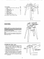
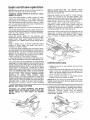
ASSEMBLING
STEEL
LEGS
1_ insert the Truss Head Screws through the holes
in the legs, then through
the holes in the
stiffeners,
MAKE SURE THE SCREWS GO
THROUGH
THE
HOLES
iN THE
SIDE
STIFFENERS MARKED "X"
2 Install Iockwashers and screw on the nuts, butdo
not tighten until completely assembled
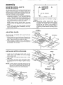
3 Install leveling feet as shown, To level Leg Set,
loosen nut on inside of leg and turn nut on outside
to raise or' lower feet, Adjust all four levelers, if
necessary, and then tighten nuts on inside of leg
NOTE: These levelers are not intended for height
adjustment
SIDE
STIFFNER
END
STIFFNER
SCREWS THROUGH
HOLES MARKED "X"
1/2 IN, HEX NUTS
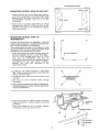
SAW
MOUNTING
HOLES
/
MOUNTING
SCROLL
SAW
ON
LEG
SET
O
oOO
1 Place the Scroll Saw on the Steel Legs, position
as shown by aligning the mounting holes in the
base of the Scroll Saw with those in the END
STIFFENERS
(marked
with an X in the
illustration)
O
oo
O
O
0 Oo
REAR
_--
o
o
o
o
S
o
O
%
2 Mount saw to Leg Set using three (3) 1/4-20
carriage bolts, three (3) I/4-20 nuts, three (3)flat
washers, and three (3) 1/4" Iockwashers Tighten
nuts using wrench
MOUNTING
SCROLL
WORKBENCH
o
o
o
o
0
0oO
o
FRONT-_::_
SAW TO
Anytime the Scroli Saw is in operation, it must be
fastened securely to a firm, supporting surface such
as a Leg Set (9-22239) or a workbench
When mounting Scroll Saw to a workbench, holes
should be drilled through supporting surface of the
workbench using dimensions illustrated
! Scroll Saw should be bolted securely using the
following hardware found in Loose Parts Bag:
Four (4) 1/4-20 carriage bolts, four (4) 1/4-20
nuts, four
(4) flatwashers,
and four
(4)
fockwashers, Bolts must be of sufficient length to
accomodate
the saw base, rubber bumpers,
washers,
hex nuts, and thickness
of the
supporting surface
2 Locate four (4) rubber bumpers in Loose Parts
Bag These should be used when mounting Scroll
Saw on a solid surface
3 Locate and mark holes where Scrot{ Saw is to be
mounted
4 Drill four (4) 5/16" diameter
holes through
workbench
.J
_l
o
O
f,/)_
o
lZ
o
___5/16"
D1A. HOLES (4)
12-1/2"
\
/
PLACE RUBBER BUMPERS
OVER HOLES IN
WORKBENCH
5, Place rubber bumpers over holes in workbench,
with large opening in rubber bumper against top
surface of workbench
6 Place Scroll Saw on rubber bumpers and align
holes in workbench, rubber bumpers, and Scroll
Saw Base,
7 insert and tighten all four (4) bolts, washers,
Iockwashers, and nuts using wrench
_
CARRIAGE
BOLT
II RUBBER
BUMPER
assembly
MOUNTING
MOUNTING
SCROLL
BOARD
24
SAW
TO
FROM BOTTOM
OF MOUNTING
COUNTER
SINK
BOARD
__
An alternate method of mounting is to fasten Scroll
Saw to a mounting board The board should be of
sufficient size to avoid tipping of saw while in use.
Any good grade of plywood or chipboard with a 3/4"
minimum thickness is recommended._
1 Follow instructions for mounting to a workbench,
substituting a board 12"x 24" minimum size and
using 1/4 inch fiat head screws, Iockwashers, and
hex nuts, Screws must be of sufficient length to
accomodate saw base, rubber feet, washers, hex
nuts, and thickness of supporting board
NOTE: Holes must be counter sunk so screw
heads are flush with bottom surface of supporting
board
Locate, mark, and drill holes through mounting
board, and install screws, iockwashers, and nuts
Tighten with wrench
ii
ii llll
ii lllll
ii
.e
_ ....
p.
J
16"
"_----_
DIA,
HOLES{4)
12-1/2
=[
3. Securely clamp board to workbench
using C
clampsr
NOTE: Supporting
surface where Scroll Saw is
mounted should be examined carefully after
mounting
to insure that no movement
during use can result, if any tipping or
walking is noted, secure workbench, legs, or
supporting surface before operating Scroll
Saw.
ii, ,ll,i
i
GUARD
LOCK KNOBS
ADJUSTING
GUARD
The Scroll Saw is shipped with a guard arid lock
knobs installed
1 Adjust guard by loosening the two (2) guard lock
knobs and raising guard to desired height above
table Tighten guard lock knobs by hand.
2 Guard should be against top of workpiece to
provide additional control, but permit movement
of workpiece, flat on table.
GUARD
WORKPIECE
L
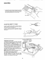
INSTALLING
MITER
LOCK
KNOB
WEDGE
1 Locate one (1) miter gauge lock knob, one (1)
13/64 x 5/8 x 1/32 washer, and one (1) wedge
among loose parts
2. Insert wedge into tapered recess next to front
miter slot
3 Install washer and knob from underside of table,
by engaging knob into wedge.. Tighten knob by
hand
NOTE: A miter gauge is included with the Scroll
Saw With the wedge locking feature, the
operator can use the miter guage to perform
ripping as well as miter and crosscuts.
1
{
t
WASHER
MITER GAUGE,__
LOCK KNOB
MITER
_J_
GAUGE
MITER
GAUGE
BLADE DNSTALLATUON
AND
TENSIONnNG
FOR PLAnN-END
OF{ PRN TYPE BLADES
NOTE: Included with the scroll saw are three 5"
blades. This saw can accommodate 5" to 6" plainend blades, and 5" pin type blades.
'TO INSTALL/TENSION
BLADES:
PLAIN-END
WARNING:
FOR YOUR OWN SAFETY, TURN
SWITCH "OFF", REMOVE KEY AND REMOVE
PLUG FROM POWER SOURCE OUTLET BEFORE
REMOVING OR INSTALLING SAWBLADE.
NOTE: Use blade holder pockets to verify correct
blade length and positioning
1 Locate four (4) blade holders, four (4) 10-32 x 1/4
set screws, one (1) blade, four (4) blade clips, and
one (1) set screw wrench among loose parts Two
(2) extra blade holder assemblies are provided for
quick and convenient changing of blades,
2 Insert one (1) blade clip into each blade holder by
pushing clip through holder until it snaps into
place catching upper ledge. Insert one 10-32 x 1/4
set screw into each blade holder
3 insert btade into one holder by pushing short side
of blade clip towards set screw, installing blade,
and releasing side of blade clip Place holder into
blade holder pocket in table (set screw side
upward) and check for proper extension squaring
blade to opposite blade holder pocket center
point Tighten set screw with wrench provided,
4. Insert blade into other holder (as described
above) Place both holders in pockets in table to
achieve proper spacing and tighten other set
screw
5 Place holder assembly in table insert hole; make
sure the teeth are pointing downward.
BLADE
SHORT
BLADE
SIDE
CLIP
BLADE HOLDERS
IN BLADE
HOLDER POCKETS
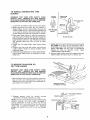
6 Set notches in blade holders into slots inside upper
and lower arm end caps The blade holders provide
slots for orientating biade in any 90 ° position.
NOTE: Blade holders do not touch the retainer clips after
being properly installed
The purpose of the retainer
clips is to deflect the blade holders if the blade breaks
UPPER
ARM
END CAP
SLOT IN
END CAP
NOTCHIN
BLAOEHOLDER
9
assembly
7 Locate table insert among loose parts and install
in table by sliding the insert in place from back to
front of blade, aligning rear tab on back of insert,
and pushing downward on front of insert
t'l
TABLEINSERT
ADJUSTING
INSERT
TO
TABLE
if insert is higher than table top, adjust insert by
tapping lightly with hammer at each tab location
until insert is flush with table top
If insert is lower than table top, adjust insert by
slightly bending down all four tabs with a needle
nose pliers
TENSIONING TENSION
TENSIONING THE BLADETo apply the proper tension to the blade after blade
and holders are securely in place, turn the tension
knob clockwise
BY HAND until tight, (5 full
revolutions
with a wide blade; up to 7 full
revolutions with a narrow blade) DO NOT use any
type of mechanical device or tool on tension knob
As tension is being applied, recheck the aNgnment
of the blade holder notch in the end cap slot
To check blade tension _ push thumb against sideof
the blade in the middle Blade should move only
slightly with moderate pressure
NOTE: Blades tend to break more easily with too
little tension than with too much tension
TO CHECK BLADE INSTALLATIONWith blade properly installed and tensioned, place
fiat-head
screwdriver
in motor siot and rotate
manually by turning screwdriver to check correct
installation and clearance of the blade,
KNOB
BLADE
10
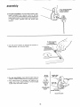
TO INSTALL/TENSION
BLADES:
PIN TYPE
BLADE
WARNING:
FOR
YOUR
OWN
SAFETY,
TURN
SWITCH
='OFF",
REMOVE
KEY AND REMOVE
PLUG FROM POWER SOURCE
OUTLET
BEFORE
REMOVING
OR INSTALLING
SAWBLADE,
HOLDER
l
BLADE
t Locate two (2) blade holders among loose parts
2 Blade clips and set screws are not needed in
blade holders with pin type blades; they can be
stored in base of unit. If previously installed there
is no need to remove clips and screws, but set
screws should be securely tightened in holders
3 Place each blade holder in upper and lower arm
cap ends (with pin-blade slot closest to table) by
pulling retainer clips up and aligning notches in
blade holders with slot in cap Position pin-blade
slot towards table and front of saw for easy
access
4 Locate two (2) blade holder keys among loose
parts.
5 Position one key over top holder, and one key
under bottom holder to secure holders while
installing blade.
6 Install (pin type) blade first in lower blade holder,
then in upper blade holder by sliding pin into pin =
Made slot
TO REMOVE
PLAIN-END
PIN TYPE BLADES
UPPER ARM
END CAP
HOLDER
KEY
PIN-BLADE
SLOT
BLADE
HOLDER
7, Apply tension by turning tension knob clockwise
BY HAND until tight (5 full revolutions with a
wide blade; up to 7 full revolutions with a narrow
blade)
DO NOT use any type of mechanical
device
or tool
on tension
knob
(See:
TENSIONING THE BLADE),
8, Remove blade holder keys from upper and lower
blade holders and store keys for future use
OR
WARNING:
FOR YOUR OWN SAFETY, TURN
SWITCH "OFF", REMOVE KEY AND REMOVE
PLUG FROM POWER SOURCE OUTLET BEFORE
REMOVING OR INSTALLING SAWBLADE.
Remove table insert by pushing gently upward at
back of insert and pulling back of insert up to
release front insert tab Move insert backward to
clear blade from insert slot
PUSH BACK END
OF INSERT
UP FIRST
2 Release tension
knob by turning
counter
clockwise until blade assembly is loose
NOTE: Do not turn knob beyond point where blade
loosens because the knob could disengage
if
turning continues
tf knob is turned too far and
disengages from rod, slowly tilt up on outer end of
upper arm to expose threaded
rod Carefully
engage flat washer and knob on rod, and tighten
knob
TENSION
THREADED
11
KNOB,_-
ROD__R
_
--_
l
-
assembly
3. For plain-end blades, remove blade holders (with
blade installed) from retainer clips by putling
clips away from blade holders. Pull out upper and
Iowe_ blade holders Ptace blade ho(der' assembly
in blade holder pockets with set screw side
upward
BLADE
4 Use set screw wrench to remove set screws
blade holders, and remove blade
HOLDERS
///J
" _'
HOL' .% ETS
,,I,,--.
/
in
BLADE
UPPER
ARM
HOLDER
5. For pin type blades, place blade holder keys as
shown on blade holders before releasing tension
6 After blade tension is released, pull blade out of
upper and lower blade holders, remove blade
holder keys and blade holders
SLOT
I_!J
_
PIN-BLADE
SLOT
BLADE HOLDER
BLADE
12
/
HOLDER
ADJUSTING
TO TABLE
THE
BLADE
SQUARE
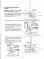
WARNING:
FOR YOUR OWN SAFETY, TURN
SWITCH "OFF", REMOVE KEY AND REMOVE
PLUG FROM POWER SOURCE OUTLET.
COMBINATION
SQUARE
GUARD
1, WITH BLADE INSTALLED AND TENSIONED
place combination
square on side of blade,
Guard prevents placing square directly against
blade, so gauge squareness of blade to table by
viewing from side of saw,,
BLA[
HOUSING
2 If an adjustment is necessary, foosen four (4) hex
bolts located at back of lower arm on saw using
7/16" wrench. Align blade square to table by
tilting
housing
forward
or backward,
and
retighten all four (4) bolts
NOTE: Make certain the blade is centered in the
insert
opening
Readjust
if necessary
by
loosening
four hex head bolts and moving
housing to center the blade Retighten bolts
HEX HEAD BOLTS
3 Place square in front of blade Guard prevents
placing square directly against blade, so gauge
squareness of table to blade by viewing from front
of saw
4 If an adjustment is necessary, loosen bevel lock
knob located under base and rotate housing
slightly to align blade to combination
square
Tighten bevel lock knob
HOUSING
BEVEL
LOOK
NOB
BLADE _
BEVEL
J
LOCK
KNOB
F
13
CO ,¢2#,ON
assembly
INSTALLATION
PEEL OFF THIS PIECE OF SCALE BACKING
FIRST
OF BEVEL SCALES
1 With blade installed and tensioned, Iocatetwo (2)
bevel scales among loose parts
2 Locate slit in paper backing on back side of scale.
Remove backing on the zero end of scale.
3 While holding scale by the end still protected by
the backing, lightly position unprotected end in
the scale recess and slide it under the indicator
Align the zero mark with the indicator and press
the scale to the base.
(2ND SCALE
RECESS
IN BASE
LINE UP "0"
POSIT!ON}
MARK WITH INDICATOR
=[lllUil,llllll=U=
1=k
TILT HEAD TO CLEAR SCALE
4. Loosen bevel lock knob located under- the base
and tilt head away from scale
5 Fold scale back and remove remaining paper
backing. Press entire scale against base Smooth
out any wrinkles or air bubbles.
6 Repeat on opposit# side
BEVEL LOCK KNOB
14
JJ
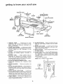
getting to know your scrota saw
I
TENSION
\
KNOB
2
GUARD LOCK
KNOBS
3
GUARD
13
ON/OFF
SWITCH
BLADE
5
HOLDER
4
RETAINING
CLIP
BLOWER
6
TUBE
BLADE HOLDERS
7
BLADE HOLDER
POCKETS
12
BEVEL
SCALES
11
BEVEL
LOCK KNOB
,
T
TABLE INSERT
8
MITER
LOCK KNOB
10
BLADE STORAGE
10, BLADE STORAGE.,,
Space provided in the saw
base for extra blades, holders, and set screw
wrench
11. BEVEL LOCK KNOB...
Loosening knob allows
blade and housing assembly to tilt up to 45 °
right or left for bevel cuts
12. BEVEL SCALES..,
Shows degree blade is tilted
for bevel cutting
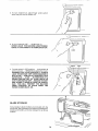
13. ON-OFF SWITCH...
The On-Off Switch has a
locking feature. THIS FEATURE 1S INTENDED
TO PREVENT
UNAUTHORIZED
AND
POSSIBLY HAZARDOUS USE BY CHILDREN
AND OTHERS
1 lnsert Key into switch
NOTE: Key is made of yellow plastic
1. TENSION
KNOB . . . Tightening
the knob
(clockwise)
wilt increase the tension on the
blade
Loosening it (counter clockwise)
wilt
decrease the tension
2, GUARD LOCK KNOBS...
Loosening the knobs
will allow the guard to be adjusted to the proper
working
height for the thickness
of the
workpiece
3. GUARD,,, Provides added control of workpiece
by being set directly against thickness
of
material
4. BLOWER TUBE . , ° Clears pattern lines on
workpiece
by blowing off sawdust particles
which can accumulate while cutting. Tube is
mounted directly behind the blade on the guard,
and it operates whenever saw is on
5. BLADE HOLDER RETAINING CLIPS...
Aid in
positioning,
retaining,
and releasing
blade
holders
6. BLADE HOLDERS ..o Retain and position the
blade
7, BLADE HOLDER POCKETS... Helpoperator
to
accurately align, position, and tighten blade in
blade holders by securing holders during blade
installation
8. MITER GAUGE LOCK KNOB o o , Turning the
knob tightens wedge in miter slot to aIlow miter
gauge to be securely locked in either of the two
intersecting
miter slots Several types of cuts
can be made from various miter gauge positions
9, TABLE INSERT...Removes
for clearance and
viewing during blade assembly installation, and
locks in table while sawing
KEY
@
KEY
YELLOW
15
PLASTIC
I
2 To turn machineon, placefinger underswitch
leverand pull endof switchout
\
3. To turn machine OFF...
PUSH lever in.
NEVER LEAVE THE MACHINE UNATTENDED
UNTIL IT HAS COME TO A COMPLETE STOP,
PUSH
HOLD
\
4 To lock switch in OFF position .. hold switch IN
with one hand...
REMOVE key with other hand.
WARNING: FOR YOUR OWN SAFETY, ALWAYS
LOCK THE SWITCH "OFF" WHEN MACHINE IS
NOT IN USE... REMOVE KEY AND KEEP IT IN A
SAFE PLACE..,
ALSO. _. tN THE EVENT OF A
POWER FAILURE (ALL OF YOUR LIGHTS GO
OUT) TURN SWITCH OFF... REMOVE THE KEY
AND STORE IT REMOTE FROM THE SCROLL
SAW. THIS WILL PREVENT THE MACHINE
FROM STARTING
UP AGAIN WHEN THE
POWER COMES BACK ON.
BLADE
STORAGE
Extra blades & blade holders are included with the
scroll saw See illustration for location of storage for
blades and holders, and also storage for set screw
wrench
PULL
basic scronHsaw operation
INSTALLATION-GETTING
SCROLL
SAW)
Remove
and store for future use
NOTE: Make certain set screws in blade holders are
tight prior to each use of the scroll saw
WARNING: NEVER OPERATE WITHOUT TABLE
INSERT IN PLACE°
TO
KNOW
YOUR
two (2) blade holder keys
Plain-end blades can be used for inside cutting.
Follow the procedure for pin-type
blades, and
loosen set screws in upper and lower blade holders
using set screw wrench When installing blade in
blade holders, tighten set screws with wrench
Use caution when cutting off material which is
irregular in cross section which could pinch the
blade before the cut is completed
A piece of
molding for example must lay flat on the table and
not be permitted to rock while being cut
This scroll saw accepts a wide variety of blade
widths and thicknesses: 5" to 6" length plain end
type blades and 5" length pin type blades The blade
size (thickness and width) and the number of teeth
per inch are determined by the type of material and
the smallest radius being cut
NOTE: Use wider blades to achieve straightest cuts
A scroll saw is basically a "curve cutting" machine It
can also be used for straight-line cutting operations
such as cross cutting, ripping, mitering, beveling,
and compound cutting.
Using the proper blade for the material and
thickness being cut will help the operator to follow
pattern lines. (Use wider blades to achieve the
straightest cuts ) Blade teeth should always point
down
When a blade is dull, or when insufficient blade
tension is being used, the blade may have a
tendency to twist or break
To minimize blade breakage and to produce more
accurate results, be sure the blade is not forced into
the workpiece. Too much pressure should not be
applied on the wood as it is fed into the blade.
Steady, even pressure will produce more uniform,
cleaner cutting with less blade breakage.
Loosen blade tension knob when scroll saw is not in
use.. Follow procedure to tension blade before use.
Use caution when cutting off round material such as
dowel rods, or tubing They have a tendency to roll
while being cut causing the blade to "bite" Always
use a "V" block, or clamp round material to a miter
The scroll saw has the capability of inside cutting
(piercing). Pin-type blades are recommended when
inside cutting as the best type of blade to use for
maximum performance
Drill an over-sized hole in
scrap section of workpiece
Locate two (2) blade
holder keys among loose parts Position each key
over one installed blade holder to secure holder
while installing blade through workpiece. Release
tension
knob
(see BLADE
INSTALLATIONGETTING
TO KNOW YOUR SCROLL
SAW)
Remove blade, and place workpiece on table with
drilled hole aligned over blade slot in insert. Replace
blade, sliding it through drilled hole and insert slot.
Reinstall blade in lower and upper blade holders.
Retighten
tension
knob
(see
BLADE
SAWING/SCROLLING
1 Adjust the guard to just contact the top of the
workpiece
2 Use both hands while feeding the work into the
blade Hold the workpiece firmly against the
table Use gentle pressure, and do not force the
work, but allow the blade to cut
3 Avoid putting side loads on the blade during
cutting to keep cut square to table
NOTE: When very sharp curves are to be cut, narrow
blades should be used Remove blade clips when
using narrow blades
BEVEL SETTING/CUTTING
Loosen bevel lock knob and tilt housing of saw to
the desired angle degree by reading bevel scales
Adjust the guard to just contact the top of the
workpiece
Perform
bevel cuts
by feeding
workpiece into blade without a guide or using the
miter gauge HOUSING
WARNING: TO AVOID _ RUNNING THE MITER
GAUGE INTO THE GUARD, ALWAYS SET THE
BEVEL ANGLE TO THE RIGHT AS SHOWN
BELOW,
BEVEL
LOCK KNOB
17
basic scroll saw operation
USE OF MITER
GAUGE
CROSS
CUTTING
-
MITER GAUGE
FACE
MITER GAUGE
WARNING:
TO AVOID
WORK INSTABILITY
OR
RUNNING
THE MITER GAUGE INTO THE BLADE,
TURN THE MITER GAUGE
FACE TOWARD
THE
BLADE AND USE THE MITER SLOTACROSSTHE
TABLE FRONT FOR ALL ANGLES OVER 55° . USE
THE SLOT PARALLEL TO THE SAW ARM FOR ALL
OTHER ANGLES°
To perforrn a miter or crosscut
on the scroll saw, do
not use miter gauge lock knob and wedge
(Store
knob and wedge for future use) Adjust the guard to
just contact
the top of th,_. _.',orkpiece
The miter slot
running pa,.,liel
to saw arm sftould
be used when
blade teeth are in th, e fl unt position
Hoid workpiece
against
face of miter gauge, and cut off board at
desired
dimension
by pushing
miter
gauge and
board forward.
USE
OF MITER
GAUGE
WORKPIECE
NOTE:
Use wider
blades
to achieve
To perforrn a rip cut on the scroll saw, use the miter
gauge lock knob and wedge to secure the miter
gauge
in the slot
The miter slot running
perpendicular to the saw arm should be used when
ripping boards less than 18 inches in length and
when the blade teeth are in the front position, The
miter slot running parallel to the saw arm should be
used for ripping longer boards and when blade teeth
are in the side position, Ad ust the guard to just
contact the top of the workpiece, Tighten mter
gauge lock knob at desired setting and feed
workpiece into blade using miter gauge faceasa rip
fence. Miter gauge head must be oriented and
locked at 0 ° miter angle position to perform a rip
cut
cuts,.
i
,i,,,
maintenance
WARNING:
FOR YOUR OWN SAFETY, TURN
SWITCH "OFF", REMOVE KEY AND REMOVE
PLUG FROM POWER SOURCE OUTLET BEFORE
MAINTAINING
OR LUBRICATING
YOUR SAW.
GENERAL
Keep your Scroll Saw clean,
Do not allow pitch to accumulate on the table, tabIe
insert, blade or biade holders
Clean them with
Craftsman Gum and Pitch Remover
Apply a thin coat of automobile-type
wax on the
table so the wood slides easily while cutting Also
apply wax to the inside surfaces of the trunnion
(base)
cuts
WARNING:
NEVER
LEAVE
THE MITER
GAUGE
LOOSE
ON THE SAW. VIBRATION
MAY CAUSE
HAZARDOUS
MOVEMENT.
- RIPPING
NOTE: Use wider blades to achieve straightest
straight
ARM
PIVOT
BEARINGS
RECOMMENDED
MOTOR
Frequently vacuum or blow out any sawdust from
the motor
If the power cord is worn, cut, or damaged in any
way, have it replaced immediately
ACCESSORIES
Item
Leg Set
Blades ................................
Casters .......................
9-22239
See Cata{og
9-22221 or 9-222)2
...................................
LUBRICATION
WIRING
Ali of the BALL BEARINGS
are packed with grease
at the factory,
They require
no further lubrication,
Lubricate
arm pivot bearings
occasionally
with light
weight machine
grade oil, or 20 weight
motor oil
MultFpurpose
household
lubricants
may also be
used,
DIAGRAM
SWITCH
BLACK
=t___..
_
W.,TO
(-- .
WHITE
CON.ECTOR
,v
J_-_"
_'-
GROUND
SCREW
t
O
"_-_..,_
MOTOR
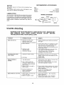
trouble shooting
WARNING: FOR YOUR OWN SAFETY, TURN SWITCH
AND
REMOVE
PLUG
FROM
POWER
SOURCE
TROUBLESHOOTING
YOUR SCROLL SAW.
TROUBLE
PROBABLE
Motor will not run.
CAUSE
REMEDY
1 Defective On-Off switch
Defective switch cord
Defective switch box receptacle
2 Motor Defective
3 Cutting too fast,
defective blade;
mechanism jammed
Scroll Saw slows down
when cutting°
1 Cutting
too small a radius
2 Dull blade
Blades breaking or
bending,
1 Too little tension,,
2 Kink in blade caused by
cutting too small a raduis or
turning the material too fast
when cutting
3 Blade not set far enough in
blade holders
4 Forcing workpiece into
blade or sideloading
blade excessively
Blade
twisted
or out of line.
"OFF", REMOVE KEY
OUTLET
BEFORE
! Blade Holders incorrectly set
in arm end caps
2 Blade not square to table
19
1 Replace defective
Saw again
parts before
using Scroll
2 Consult Sears Service Any attempt to repair
this motor may create a HAZARD unless
repair is done by a qualified service
technician, Repair service is available at your
nearest Sears Store
3 A slot has been provided in the end of the
motor shaft to insert screwdriver to
manually cycle motor Unit must be
unplugged from power source
1 Stop feeding, and back up to the material
slightly, until the scroll saw speeds up; use
smaller blade
2 Replace blade
1 Adjust tension, See "Getting To Know Your
Scroll Saw Tension Setting"
2 Use correct cutting technique
See "Basic
Scroll Saw Operation"
Section
3 Remove blade holder assembly and reinstall
blade correctly in holders See " Assembly
Blade Installation"
4 Do not force workpiece
AIfow
blade to cut Avoid applying
excessive sideload
1 Adjust blade holders -- See "Assembly
Blade Installation"
2, Adjust blade to table - See "Assembly Adjusting the Blade Square to Table"
,
)
PARTS
LIST
FOR CRAFTSMAN
18-INCH
MOTORIZED
MODEL
NO. 113.207600
AND 113.207650
SCROLL
SAW
3
63
57
55 56
4O
41
43
66
FIGURE
2O
1
PARTS
LIST
FOR CRAFTSMAN
18-INCH
MOTORIZED
MODEL
NO. 113.207600
AND 113.207650
Always order by Part Number
FIGURE
%_oy
Part
No.
t
I STD601105
2
3
4
5
6
166015
166016
166o05
} 66032
f 60464
7 I SJ_D551010
8
9
10
11
12
/ 66021
/ 66034
_ 66024
/ 66009
/ 66019
t3 ! 60527
14
66011
15 I
16
I 17
I 18
I 19
I 20
I 21
I 22
23
I 24
} 25
26
/ 27
28
I 29
30
31
32
/ 33
66029
66010
66007
STD54t408
66014
STD551012
STD551231
60460
66018
809102-2
60129
60461
66036
60467
60466
66035
62442
60256
I 34
STD601103
Tube Assembly,
Retainer
1
35
36
37
38
39
40
*Screw, Pan Cross Type "T"
10-32 x 1/2
Cover, Motor
Fan
Motor
Housing Assembly
Spacer
*Washer, 13/64 x 7/16
x 025
Knob
I STD551210
166025
166030
166O33
ISTD551206
160459
*Lockwasher, External No 10
Rod, Tension
Wedge, Rip Fence
Insert Assembly
*Lockwasher, Internal No 6
Screw, Fil Hd Type "T"
10_32 x 1 3/8
41 ISTD600603
*Screw, Pan Sl Type "T"
6-32 x 5/16
Panel, Trim
Knob, Miter Gauge
Bolt, Carriage 1/4_20 x 2-1/2
Bumper, Rubber
'Lockwasher,
1/4
*Nut, Hex 1/4-20
Washer, 21/64 x 47/64x 1/16
Knob
Clip, Trunnion
Base
Scale, Bevel
Bracket, Trunnion
*Bolt, Carriage 5/16-18 x 3/4
Lockwasher, External 1/4
*Screw, Hex Hd 1/4-20 x 3/8
Spacer
Pump
Tubing
Nut, 5/16
Spring
*Screw, Set 1/4-20 x I/4
Relief, Strain
Cord with Plug
Connector, Wire
Gauge Assembly, Miter
Key, Blade Holder
Wrench, Hex L 3/32
Owner's Manual (Not
Illustrated)
Bag of Loose Parts (Not
Illustrated)
43 162176
44 160526
45 1805116
46 ISTD551125
47 1STD541025
4B 160465
4_ 163387
50 166012
5! !66006
52 166026
53i66008
54 ! STD533107
55 STD551225
56 STD522503
57 60463
58 66023
59 66028
60 27733
61 66027
62 STD502502
63 37818
64 66013
65 803709
66 62170
67 66020
68 37836
66017
Cap
Holder, Blade
Screw, Hex Soc Half Dog
Set 10-32 x 1/4
Clip, Blade
tBlade, Scroll Saw
Wedge, Blade Tension
Channel, V
Bearing, Flanged
"Nut, Hex Locking 8-32
Counterbalance
*Washer, 17/64 x 1/2 x 1/32
*Lockwasher, Internal 5/16
Screw, Shoulder 5/16
Guard, Blade
Knob
Washer, 21/64 x 1/2 x 1/32
Screw, Hex Cap 5/16-18 x 2
Link Assembly
Ring, Retaining
Washer, ,190 x 88 x 040
Tube Assembly Lower
Switch, Locking
Key, Switch
*Screw, Pan Cross Type "T"
10-32 x 5/16
66031
*Standard
hardware
Description
Part
No,
42 i66022
Upper
items - may be purchased
locally
I" Stock Item - May be secured through the Hardware Dept
of most Sears Retail Stores or Catalog Order Houses
21
SAW
- Not by Key Number
Key I
No, I
Description
SCROt.L
PARTS LIST FOR CRAFTSMAN 18-INCH MOTORIZED SCROLL SAW
MODEL NO. 113.207600 AND 113,207650
8
FIGURE
Key
No.
H,
2 - MITER
GAUGE
Pa rt
No.
ASSEMBLY
Description
ii
1
2
3
4
5
6
7
8
62170
62176
STD551010
62173
62175
STD510802
38724
62117
62174
*Standard
hardware
Gauge Assy, Miter
Knob, Miter Gauge
*Washer, 13/64 x 5/8 x 1/32
Gauge, Miter
Pin, Miter Pivot
*Screw, Pan Hd 8-32 x 1/4
Pointer
Spacer
Bar, Miter Gauge
items - may be purchased
22
locally
PARTS
LIST
FOR CRAFTSMAN
18-INCH
MOTORIZED
MODEL
NO. 113.207600
AND 113.207650
4
SCROLL
SAW
5
3
o
6
_tj
|
\
2
'_o
6
2
FIGURE
3 - LEG
MODEL
113.207650
SET
FOR
ONLY
,,,J,l,,.
Key
No.
Part
No.
Description ........
1
60314
2
3
4
5
6
63749
62554
STD551225
STD541025
7
8
STD541250
803835
66037
62615
HARDWARE
FOR
STD551012
STD522512
*Standard Hardware
t Bag contains
Screw, Serrated Truss Hd
1/4-20 x 5/8
Leg
Stiffener, Side
*Lockwasher, Ext 1/4
*Nut, Hex 1/4-20
Stiffener, End
*Nut, Hex 1/2-13
Foot, Leveling
t Bag of Loose Parts
(not illustrated)
MTG. TOOL.
*Washer, 17/64 x 9/16 x 3/4
*Screw, Hex Hd 1/4-20 x
1 1/4
Items -- May be Purchased
Locally
all Loose Parts for Legs
23
5
4
2
]
18-iNCH
MOTORIZED
SERVICE
SCROLL
SAW
Now that you have purchased your 18-inch motorized Scrolf Saw
should a need ever exist for repair parts or service, simply contact
any Sears Service Center and most Sears, Roebuck and Co
stores° Be sure to provide all pertinent facts when you call or visit
MODEL NO
113.207600
SAW ONLY
MODEL NO.
113.207650
SAW WITH
LEGS
HOW TO ORDER
REPAIR
The model number of your 18-inch motorized Scroll Saw will be
found on a plate at the right hand side of the saw.
WHEN ORDERING
REPAIR
FOLLOWING INFORMATION:
PARTS,
ALWAYS
GIVE
THE
PARTS
PART NUMBER
PART DESCRIPTION
MODEL NUMBER
113.207600 or'
113.207650
NAME OF ITEM
18-Inch Motorized Scroll Saw
All parts listed may be ordered from any Sears Service Center
and most Sears stores If the parts you need are not stocked
locally, your order will be electronically
transmitted to a Sears
Repair Parts Distribution
Center for handling
Sold
Part Noo66017
by SEARS,
ROEBUCK
AND
CO.,
Form NOo SP4701-5
Chicago,
IL. 60684
U.S.A.
Printed in US A, 11/89