1
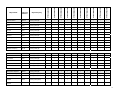
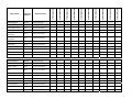
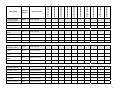
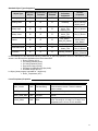
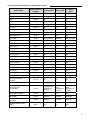
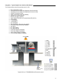
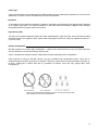
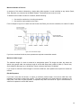
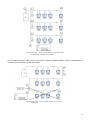
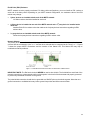
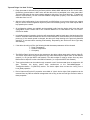
PIR Ready VT76xx Series Programmable & Non-Programmable Thermostats For Commercial HVAC Applications BACnet Integration Manual September 1, 2010 1 Product Overview The VT76xx PI thermostat family is specifically designed for single stage and multi-stage control of heating/cooling equipment such as rooftop and selfcontained units. The product features an intuitive, menu-driven, back-lit LCD display, which walks users through the programming steps, making the process extremely simple. Accurate temperature control is achieved due to the product’s PI time proportional control algorithm, which virtually eliminates temperature offset associated with traditional, differential-based thermostats. The thermostats are also compatible with the new Vykon PIR cover accessories. Thermostats equipped with a PIR cover provide advanced active occupancy logic, which will automatically switch occupancy levels from Occupied to Unoccupied as required by local activity being present or not. This advanced occupancy functionality provides advantageous energy savings during occupied hours without sacrificing occupant comfort. All thermostats can be ordered with or without a factory installed PIR cover. The additional following documentation is available: - VYKONStat PIR Ready VT7600 Series Thermostat Installation Guide - VYKONStat PIR Ready VT76x7 Series Thermostat Installation Guide - VYKONStat PIR Application Guide - VYKONStat PIR Cover Assembly Installation Guide Contents Subject VT76xx series Protocol Implementation Conformance Statements (PICS) Objects Table Standard Object Types Supported List of Proprietary Properties List of Property Value Range List of Property Enumeration Set for BI's and BV's List of Property Enumeration Set for MV's Integration - Global commands Integration - Graphic User Interface (GUI) Objects Integration - Configuration Objects Wiring Guide Overview Network Configuration Maximum Number of Devices Maximum Cable Length EI-485 Repeaters End Of Line Resistors Network Adapter Default Device Name and Device ID Integrating Vykon’ Devices on an MSTP Network Tips and Things You Need To Know Troubleshooting Section 2 VT7600 series Protocol Implementation Conformance Statement (PICS) Vendor Name: Vykon Vendor ID: 140 Product Name: VT7600 Thermostat Series Product Model Number: VT7600A5X28B, VT7600B5X28B, VT7605B5X28B, VT7607B5X28B, VT7600H5X28B, VT7652A5X28B, VT7652B5X28B, VT7656B5X28B, VT7657B5X28B and VT7652H5X28B. Product Description: The VT76xx series BACnet communicating thermostat have been specifically designed for RTU and heatpump applications to be monitored on a BACnet MS-TP® network. Supported BACnet Services The BACnet communicating thermostat meets all requirements for designation as an Application Specific Controller (B-ASC). The BACnet thermostat series supports the following BACnet Interoperability Building Blocks (BIBBs). Application Service Designation Data Sharing – Read Property - B DS-RP-B Data Sharing – Read Property Multiple - B DS-RPM-B Data Sharing – Write Property - B DS-WP-B Device Management - Device Communication Control - B DM-DCC-B Device Management – Dynamic Device Binding - B DM-DDB-B Device Management – Dynamic Object Binding - B DM-DOB-B Note 1: The thermostat does not support segmented requests or responses. Note 2: Time synchronization can be made through a network even if the thermostat does not support the full date. Therefore, the device cannot claim conformance to the DeviceManagement – TimeSynchronization - B (DM-TS-B) service. The device object does not have the Local_Time or Local_Date properties. 3 Device Object Table Object Name VT76xxX5x28B Type and Instance Device Object Property Object_Identifier Thermostat Parameter Unique ID number of a device on a network Property 75 (R,W) Object_Name Unique name of a Device on a network Property 77 (R,W) Model Name Thermostat Model number Property 70 (R) Firmware Revision Current BACnet firmware revision used by the thermostat Property 44 (R) Protocol Version Current BACnet firmware protocol version Property 98 (R) Default is Version 1 Protocol Revision Current BACnet firmware protocol revision Property 139 (R) Default is Version 2 Max ADPU Length Maximum ADPU Length accepted Property 62 (R) Default is 244 ADPU Timeout ADPU timeout value Property 10 (R) Default is60 000 ms ApplicationSoftware-Version Thermostat base application software version Default is based on current released version Property 12 (R) Max_Master (R,W) Maximum master devices allowed to be part of the network. 0 to 127, default is 127 MS/TP_Address Property 1001 (R,W) BACnet MS-TP MAC Address. Proprietary attribute. Default is as assigned by configuration MS/TP_Baud_Rate Property 1002 (R,W) BACnet MS-TP Baud-Rate. Proprietary attribute. Range is: 1 = 9.6 KBps, 2 = 19.2 KBps, 3 = 38.4 KBps, 4 = 76.8 KBps and 5 = Auto Baud Rate. Index 5 is Write only. Reading attribute will state current Baud rate used. Writing index 1 to 4 will fix the Baud rate to the desired value. 4 VT7600A5x28B VT7652A5x28B VT7600B5x28B VT7652B5x28B VT7605B5x28B VT7656B5x28B VT7607B5x28B VT7657B5x28B VT7600H5x28B VT7652H5x28B Objects Table Room Temperature AV 7 Present_Value (R,W) √ √ √ √ √ √ √ √ √ √ Room Temp Override BV 8 Present_Value (R,W) √ √ √ √ √ √ √ √ √ √ Outdoor Temperature AV 9 Present_Value (R,W) √ √ √ √ √ √ √ √ √ √ Outdoor Temp Override BV 10 Present_Value (R,W) √ √ √ √ √ √ √ √ √ √ Room Humidity AV 11 Present_Value (R) √ √ Occupancy Command MV 12 Present_Value (R,W) √ √ √ √ System Mode HP MV 13 Present_Value (R,W) √ √ System Mode RTU MV 14 Present_Value (R,W) √ √ √ √ √ √ √ √ Fan Mode MV 15 Present_Value (R,W) √ √ √ √ √ √ √ √ √ √ Supply Temp AI 16 Present_Value (R) √ √ √ √ √ √ √ √ Supply RH AV 17 Present_Value (R) Keypad Lockout MV 18 Present_Value (R,W) √ √ √ √ √ Control Output GR 19 Present_Value (R) √ √ √ √ PI Heating Demand AV 20 Present_Value (R) √ √ √ PI Cooling Demand AV 21 Present_Value (R) √ √ √ Economizer Output AV 22 Present_Value (R) Object Name Type and Instance Object Property √ √ √ √ √ √ √ √ √ √ √ √ √ √ √ √ √ √ √ √ √ √ √ √ √ √ √ √ √ √ √ √ √ √ √ 5 VT7600A5x28B VT7652A5x28B VT7600B5x28B VT7652B5x28B VT7605B5x28B VT7656B5x28B VT7607B5x28B VT7657B5x28B VT7600H5x28B VT7652H5x28B Controller Status GRP 23 Present_Value (R) √ √ √ √ √ √ √ √ √ √ AUX BI 24 Present_Value (R) √ √ √ √ √ √ √ √ √ √ G Fan BI 25 Present_Value (R) √ √ √ √ √ √ √ √ √ √ Y1 Cool BI 26 Present_Value (R) √ √ √ √ √ √ √ √ √ √ Y2 Cool BI 27 Present_Value (R) √ √ √ √ √ √ √ √ W1 Heat BI 28 Present_Value (R) √ √ √ √ √ √ √ √ W2 Heat BI 29 Present_Value (R) √ √ √ √ √ √ Reversing Valve BI 30 Present_Value (R) √ √ DI 1 Status BI 31 Present_Value (R) √ √ √ √ √ √ √ √ DI 2 Status BI 32 Present_Value (R) √ √ √ √ √ √ √ √ Local Motion BI 33 Present_Value (R) √ √ √ √ √ √ √ √ √ √ Effective Occupancy MV 34 Present_Value (R) √ √ √ √ √ √ √ √ √ √ Controller Alarms GRP 35 Present_Value (R) √ √ √ √ √ √ √ √ √ √ Frost Alarm BI 36 Present_Value (R) √ √ √ √ √ √ √ √ √ √ Clock Alarm BI 37 Present_Value (R) Filter Alarm BI 38 Present_Value (R) √ √ √ √ √ √ √ √ √ √ Service Alarm BI 39 Present_Value (R) √ √ √ √ √ √ √ √ √ √ Fan Lock Alarm BI 40 Present_Value (R) √ √ √ √ √ √ √ √ √ √ Temperature Setpoints GRP 41 Present_Value (R) √ √ √ √ √ √ √ √ √ √ Occupied Heat Setpoint AV 42 Present_Value (R,W) √ √ √ √ √ √ √ √ √ √ Occupied Cool Setpoint AV 43 Present_Value (R,W) √ √ √ √ √ √ √ √ √ √ Unoccupied Heat Setpoint AV 44 Present_Value (R,W) √ √ √ √ √ √ √ √ √ √ Unoccupied Cool Setpoint AV 45 Present_Value (R,W) √ √ √ √ √ √ √ √ √ √ Object Name Type and Instance Object Property √ √ √ √ √ √ √ √ √ 6 VT7600A5x28B VT7652A5x28B VT7600B5x28B VT7652B5x28B VT7605B5x28B VT7656B5x28B VT7607B5x28B VT7657B5x28B VT7600H5x28B VT7652H5x28B General Options 1- GRP 46 Present_Value (R) √ √ √ √ √ √ √ √ √ √ Temperature Scale BV 47 Present_Value (R,W) √ √ √ √ √ √ √ √ √ √ Heating Setpoint Limit AV 48 Present_Value (R,W) √ √ √ √ √ √ √ √ √ √ Cooling Setpoint Limit AV 49 Present_Value (R,W) √ √ √ √ √ √ √ √ √ √ Heating Lockout Temperature AV 50 Present_Value (R,W) √ √ √ √ √ √ √ √ √ √ Cooling Lockout Temperature AV 51 Present_Value (R,W) √ √ √ √ √ √ √ √ √ √ Deadband AV 52 Present_Value (R,W) √ √ √ √ √ √ √ √ √ √ Heating CPH MV 53 Present_Value (R,W) √ √ √ √ √ √ √ √ √ √ Cooling CPH MV 54 Present_Value (R,W) √ √ √ √ √ √ √ √ √ √ Frost Protection BV 55 Present_Value (R,W) √ √ √ √ √ √ √ √ √ √ Aux Contact BV 56 Present_Value (R,W) √ √ √ √ √ √ √ √ √ √ Menu Scroll BV 57 Present_Value (R,W) √ √ √ √ √ √ √ √ √ √ General Options 2- GRP 58 Present_Value (R) √ √ √ √ √ √ √ √ √ √ Password Value AV 59 Present_Value (R,W) √ √ √ √ √ √ √ √ √ √ Power-up Delay AV 60 Present_Value (R,W) √ √ √ √ √ √ √ √ √ √ Temporary Occupancy Time MV 61 Present_Value (R,W) √ √ √ √ √ √ √ √ √ √ Fan Control BV 62 Present_Value (R,W) √ √ √ √ √ √ √ √ √ √ Anticycle MV 63 Present_Value (R,W) √ √ √ √ √ √ √ √ √ √ Fan Purge Delay BV 64 Present_Value (R,W) √ √ √ √ √ √ √ √ √ √ DI 1 Configuration MV 65 Present_Value (R,W) √ √ √ √ √ √ √ √ √ √ DI 2 Configuration MV 66 Present_Value (R,W) √ √ √ √ √ √ √ √ Proportional Band MV 67 Present_Value (R,W) √ √ √ √ √ √ √ √ √ √ Unoccupied Time AV 68 Present_Value (R,W) √ √ √ √ √ √ √ √ √ √ Object Name Type and Instance Object Property 7 VT7652H5x28B VT7600H5x28B VT7657B5x28B VT7607B5x28B VT7656B5x28B VT7605B5x28B VT7652B5x28B VT7600B5x28B Object Property VT7652A5x28B Type and Instance VT7600A5x28B Object Name Programmable Model Configuration Options GRP 69 Present_Value (R) √ √ √ √ √ Progressive Recovery BV 70 Present_Value (R,W) √ √ √ √ √ Event Display MV 71 Present_Value (R,W) √ √ √ √ √ Stages Configuration Options GRP 72 Present_Value (R) √ √ √ √ √ √ Heating Stages MV 73 Present_Value (R,W) √ √ √ √ √ √ Cooling Stages MV 74 Present_Value (R,W) √ √ √ √ √ √ Heatpump Stages MV 75 Present_Value (R,W) Economizer Model Configuration Options GRP 76 Present_Value (R) √ √ Economizer Changeover Setpoint AV 77 Present_Value (R,W) √ √ Economizer Minimum Position AV 78 Present_Value (R,W) √ √ Mechanical Cooling Enabled BV 79 Present_Value (R,W) √ √ Mixed Air Setpoint AV 80 Present_Value (R,W) √ √ Heatpump Model Configuration Options GRP 81 High Balance Point √ √ √ √ Present_Value (R) √ √ AV 82 Present_Value (R,W) √ √ Low Balance Point AV 83 Present_Value (R,W) √ √ Comfort Mode BV 84 Present_Value (R,W) √ √ Reversing Valve Configuration BV 85 Present_Value (R,W) √ √ Compressor Interlock BV 86 Present_Value (R,W) √ √ 8 BV 88 Present_Value (R,W) √ √ Dehumidification RH Setpoint AV 89 Present_Value (R,W) √ √ Dehumidification Hysterisys AV 90 Present_Value (R,W) √ √ Dehumidification Low OA Lockout AV 91 Present_Value (R,W) √ √ Dehumidification Lockout Functions BV 92 Present_Value (R,W) √ √ Dehumidification Output Status BI 93 Present_Value (R) √ √ Humidification Model Configuration Options GRP 94 Present_Value (R) √ √ Humidification RH Setpoint AV 95 Present_Value (R,W) √ √ Eff (Effective) Reset Humidification RH Spt (Setpoint) AV 96 Present_Value (R) √ √ Humidification High Limit Spt (Setpoint) AV 97 Present_Value (R,W) √ √ Low RH Setpoint AV 98 Present_Value (R,W) √ √ Low Temp Reset RH Setpoint AV 99 Present_Value (R,W) √ √ High Temp Reset RH Setpoint AV 100 Present_Value (R,W) √ √ Humidifier Output AV 101 Present_Value (R) √ √ Local Schedule SCH 102 Present_Value (R,W) √ √ VT7652H5x28B VT7657B5x28B RH Display VT7600H5x28B VT7607B5x28B VT7656B5x28B √ √ VT7605B5x28B VT7652B5x28B √ √ VT7600B5x28B Present_Value (R) Object Property VT7652A5x28B GRP 87 Type and Instance VT7600A5x28B Dehumidification Model Configuration Options Object Name √ 9 Standard Object Types Supported Object Type Supported Objects Dynamically Creatable Dynamically Deletable Optional Properties Supported Writable Properties ; Reliability Out_of_Service Reliability Present_Valuea Out_of_Servicea Object_Nameb Analog Input Analog Value ; Binary Input ; Binary Value ; Device ; Max_Master Max_Info_frames Object_Identifier Object_name Max_Master Group ; N/A N/A Multi-state Value ; Reliability States_Text Schedule ; Weekly_schedule Present_Value Out_of_Service Present_Value Weekly_Schedule Reliability Active_Text Inactive_Text Reliability Active_Text Inactive_Text Out_of_Service Present_Value Out_of_Service a: The following AV’s are defined as read only. When Out_of_Service properties is set to true, the Present_Value if written is not derived to the application level of the thermostat. ¾ Room Humidity (AV11) ¾ PI Heating Demand (AV20) ¾ PI Cooling Demand (AV21) ¾ Economizer Output (AV22) ¾ Eff Reset Humidification RH Spt (AV96) ¾ Humidifier Output (AV101) b: Object_Name property is writable for 1 object only : ¾ Room_Temperature (AV7) List of Proprietary Properties Property name ID BACnet Data type Major_Version 1000 CharacterString Description The version number of the BACnet communications module. This the hardware version number MS/TP_Address 1001 Unsigned Display the MAC layer address of the module MS/TP_Baud_Rate 1002 Unsigned Sensor_Offset 1005 REAL Display the communication baud rate of the module Display the temperature or humidity calibration value. The range is –5.0 deg F to 5.0 deg F for a temperature and –15% to 15% for humidity. 11 List of Property Value Range Restrictions for AI and AV objects Object Type and instance Under range value Over range value Default value Room Temperature AV 7 -40°F (-40°C) 122°F (50°C) N/A Outdoor Temperature AV 9 -40°F (-40°C) 122°F (50°C) N/A Room Humidity AV 11 0% 100% N/A Supply Temp AI 16 -40°F (-40°C) 122°F (50°C) N/A Supply RH AV 17 0% 100% N/A PI Heating Demand AV 20 0% 100% N/A PI Cooling Demand AV 21 0% 100% N/A Economizer Output AV 22 0% 100% N/A Occupied Heat Setpoint AV 42 40°F (4.5°C) 90°F (32°C) 72°F (22°C) Occupied Cool Setpoint AV 43 54°F (12°C) 100°F (37.5°C) 75°F (24°C) Unoccupied Heat Setpoint AV 44 40°F (4.5°C) 90°F (32°C) 62°F (16.5°C) Unoccupied Cool Setpoint AV 45 54°F (12°C) 100°F (37.5) 80°F (26.5°C) Heating Setpoint Limit AV 48 40°F (4.5°C) 90°F (32°C) 90°F (32°C) Cooling Setpoint Limit AV 49 54°F (12°C) 100°F (37.5) 54°F (12°C) Heating Lockout Temperature AV 50 -15°F (-26°C) 120°F (49°C) 120°F (49°C) Cooling Lockout Temperature AV 51 -40°F (-40°C) 95°F (35°C) -40°F (-40°C) Deadband AV 52 2°F (1°C) 4°F (2°C) 2°F (1°C) Password Value AV 59 0 1000 0 Power-up Delay AV 60 10 sec 120 sec 10 sec Unoccupied Time AV 68 0.5 hrs 24.0. hrs 0.5 hrs Economizer Changeover Setpoint AV 77 14°F (-10°C) 70°F (21°C) 55°F (13°C) Economizer Minimum Position AV 78 0% 100% 0% Mixed Air Setpoint AV 80 50°F (10°C) 90°F (32°C) 55°F (13°C) High Balance Point AV 82 34°F (1°C) 90°F (32°C) 90°F (32°C) Low Balance Point AV 83 -40°F (-40°C) 30°F (-1°C) -12°F (-24°C) Dehumidification RH Setpoint AV 89 15% 95% 70% Dehumidification Hysterisys AV 90 2% 20% 5% Dehumidification Low OA Lockout AV 91 -40°F (-40°C) 122°F (50°C) 32°F (0°C) Humidification RH Setpoint AV 95 10% 90% 50% Eff (Effective) Reset Humidification RH Spt (Setpoint) AV 96 0% 100% N/A Humidification High Limit Spt (Setpoint) AV 97 50% 90% 85% Low RH Setpoint AV 98 10% 90% 20% Low Temp Reset RH Setpoint AV 99 -40°F (-40°C) 15°F (-9.5°C) -20°F (-29°C) High Temp Reset RH Setpoint AV 100 20°F (-6.5°C) 55°F (13°C) 32°F (0.0°C) Humidifier Output AV 101 0% 100% N/A Object name 12 List of Property Enumeration Sets for BI and BV objects Object Name Object Type and instance Inactive_Text Default value Active_Text Room Temp Override BV 8 Normal Override Normal Outdoor Temp Override BV 10 Normal Override Normal AUX BI 24 Off On Off G Fan BI 25 Off On Off Y1 Cool BI 26 Off On Off Y2 Cool BI 27 Off On Off W1 Heat BI 28 Off On Off W2 Heat BI 29 Off On Off Reversing Valve BI 30 Off On Off DI 1 Status BI 31 Not Activated Activated Not Activated DI 2 Status BI 32 Not Activated Activated Not Activated Local Motion BI 33 No Motion Motion No Motion Frost Alarm BI 36 Off On Off Clock Alarm BI 37 Off On Off Filter Alarm BI 38 Off On Off Service Alarm BI 39 Off On Off Fan Lock Alarm BI 40 Off On Off Temperature Scale BV 47 °C °F °F Frost Protection BV 55 Off On Off Aux Contact BV 56 N.O. N.C. N.O. Menu Scroll BV 57 No Scroll Scroll Active Scroll Active Fan Control BV 62 Off On On Fan Purge Delay BV 64 Off On Off Progressive Recovery BV 70 Off Active Off Mechanical Cooling Enabled BV 79 Off On Off Comfort Mode BV 84 Comfort Economy Comfort Reversing Valve Configuration BV 85 Normally Cool Energized in Heating Normally Heat Energized in Cooling Normally Heat Energized in Cooling Compressor Interlock BV 86 Off On Off RH Display BV 88 Disabled Enabled Disabled Dehumidification Lockout Functions BV 92 Disabled Enabled Enabled Dehumidification Output Status BI 93 Off On N/A 13 List of Property Enumeration Sets for MV Objects Object Name Object Type and instance Occupancy Command MV12 System Mode HPU MV13 System Mode RTU MV14 Fan Mode MV15 Keypad Lockout MV18 Effective Occupancy MV 34 Heating CPH MV53 Cooling CPH MV54 Temporary Occupancy Time MV61 BACnet Index Text 1 2 3 1 2 3 4 5 1 2 3 4 1 2 3 1 2 3 1 2 3 Local Occupancy Occupied Unoccupied Off Auto Cool Heat Emergency Off Auto Cool Heat On Auto Smart Level 0 Level 1 Level 2 Occupied Unoccupied Temporary Occupied 1 2 3 4 5 6 1 2 1 2 3 4 5 6 7 8 9 10 11 12 13 3 CPH 4 CPH 5 CPH 6 CPH 7 CPH 8 CPH 3 CPH 4 CPH 0 hour 1 hour 2 hours 3 hours 4 hours 5 hours 6 hours 7 hours 8 hours 9 hours 10 hours 11 hours 12 hours Default value Local Occupancy Auto Auto Smart Level 0 Depends on local occupancy 4 CPH 4 CPH 3 hours 14 Object Name Object Type and instance Anticycle MV63 DI1 Configuration MV65 DI2 Configuration MV66 Proportional Band MV 67 Event Display MV71 Heating Stages MV73 Cooling Stages MV74 Heat Pump Stages MV75 BACnet Index Text 1 2 3 4 5 6 1 2 3 4 5 6 1 2 3 4 5 6 1 2 3 4 5 6 7 0 minute 1 minute 2 minutes 3 minutes 4 minutes 5 minutes None RemNSB RemOVR Filter Service Fan lock None RemNSB RemOVR Filter Service Fan lock 2 2F 3 3F 4 4F 5 5F 6 6F 7 7F 8 8F 1 2 1 2 1 2 1 2 2 Events 4 Events 1 Stage 2 Stages 1 Stage 2 Stages 1 Stage 2 Stages Default value 2 minutes None None 0.6 C 1.2 C 1.7 C 2.2 C 2.8 C 3.3 C 3.9 C 2 2 Event 2 Stages 2 Stages 2 Stages 15 Integration – Global Commands The following figure shows which objects from the thermostat can be monitored and commanded from the BAS front-end. Global commands all devices ( All thermostats ) Outdoor Temperature Outdoor Temperature and HVAC plant current mode BAS current energy savings mode Outdoor Temperature (AV9) System Mode (MV13) Fan Mode (MV15) Global commands specific devices ( Specific area thermostats ) Schedule Occupancy Command (MV12) Occupied Heating Setpoint (AV42) Unoccupied Heating Setpoint (AV44) Occupied Cooling Setpoint (AV43) Unoccupied Cooling Setpoint (AV45) Schedule and Outdoor Temperature Restrict user access to thermostat Keypad Lockout (MV18) Room Temperaturefor testing and override Room Temperature (AV7) MSTP Network BAS front-end Global Command Control Level VT7600 series tstat Device Level Figure 1: Global commands from a BAS front-end to a VT7600 series thermostat 16 Integration – Typical Graphic User Interface (GUI) Objects The following objects should be typically used in a GUI: ¾ ¾ ¾ ¾ ¾ ¾ ¾ ¾ ¾ ¾ ¾ ¾ ¾ ¾ ¾ ¾ ¾ ¾ ¾ ¾ ¾ Room Temperature (AV7); Occupied and Unoccupied Heat Setpoints (AV 42 and AV44); Occupied and Unoccupied Cool Setpoints (AV 43 and AV45); Outdoor Temperature (AV9); Supply Temperature (AI16) (If available); Occupancy Command (MV12); Effective Occupancy (MV34); System Mode RTU (MV14) or System Mode HPU (MV13); G Fan (BI25); Y1 Cool (BI26); Y2 Cool (BI27); W1 Heat (BI28); W2 Heat (BI29) or Reversing Valve (BI30); Economizer Output (AV22) (if available); Aux (BI24); DI 1 Status (BI31); DI 2 Status (BI 32); Frost Alarm (BI36) (if available); Filter Alarm (BI38) (if available); Service Alarm (BI39) (if available); Fan Lock Alarm (BI40) (if available); (BI 38) (BI 25) (BI 26) (BI 27) (BI 28) (AV22) (BI 29) (MV 12) (MV 14) (BI 24) (BI 31) (BI 32) (BI 36) (BI 39) (AV 42) (AV 43) (AV 44) (AI 16) (AV 45) Typical GUI for a VT7605B5028B with Economizer control 17 Configuration Objects The following objects and group objects should be typically used for configuration purposes: ¾ ¾ ¾ ¾ ¾ ¾ ¾ ¾ General Options 1 Group GRP 46 and its complete list of objects; General Options 2 Group GRP 58 and its complete list of objects; Programmable Model Configuration Options Group GRP 69 and its complete list of objects; Stages Configuration Options Group GRP 72 and its complete list of objects; Economizer Model Configuration Option Group GRP 76 and its complete list of objects; Heatpump Model Configuration Option Group GRP 81 and its complete list of objects; Dehumidification Model Configuration Option Group GRP 87 and its complete list of objects; Humidification Model Configuration Option Group GRP 94 and its complete list of objects; If your BAS allows you to remove objects from your database, Vykon recommends removing all configuration objects once your setup is complete. This will prevent unnecessary polling of non used objects and will help speed up the network. Wiring guide Overview Vykon uses EIA-485 as the physical layer between their devices and supervisory controllers For clarity we will use the term “Device” to represent any product with an active EIA-485 network connection, including Vykon and non-Vykon controllers. Summary Specifications: Parameter Media Characteristic Impedance Distributed capacitance Maximum length per segment Polarity Multi-drop Terminations Details Twisted pair 22AWG-24 AWG, shielded recommended 100-130 ohms Less than 100 pF per meter (30 pF per foot) 1200 meters (4000 feet) Note: AWG 18 cable Polarity sensitive Daisy-chain (no T connections) 1. Vykon’ devices are installed at both ends of the MSTP network: 120 Ohms resistor should be installed at each end. 2. A Vykon device is installed at one end of the MSTP network and a 3rd party device is installed at the other end: Install an End-Of-Line resistor value that matches the 3 rd party device instruction regarding the End-Of-Line resistors 3rd party devices are installed at both ends of the MSTP network: Follow the 3rd party device instructions regarding the EndOf-Line resistors. 510 ohms per wire (max. of two sets per segment) 64 (Vykon devices only) 3. Network Bias Resistors Maximum number of nodes per segment 128 Maximum number of nodes per network 9600, 19200, 38400, 76800 (Auto detect) Baud rate Table 1: Summary of Specifications for a Vykon’ EIA-485 Network 18 Cable Type Vykon recommends the use of balanced 22-24 AWG twisted pair with a characteristic impedance of 100-130 ohms, capacitance of 30 pF/ft or lower. A braided shield is also recommended. Impedance A value based on the inherent conductance, resistance, capacitance and inductance that represent the impedance of an infinitely long cable. The nominal impedance of the cable should be between 100Ωand 120Ω. However using120Ω will result in a lighter load on the network. Capacitance (pF/ft) The amount of equivalent capacitive load of the cable, typically listed in a per foot basis. One of the factors limiting total cable length is the capacitive load. Systems with long lengths benefit from using low capacitance cable (i.e. 17pF/ft or lower). Network Configuration EIA-485 networks use a daisy chain configuration. A daisy chain means that there is only one main cable and every network device is connected directly along its path. Figure 3 illustrates two improper network configurations and the proper daisy chain configuration. Other methods of wiring an EIA-485 network may give unreliable and unpredictable results. There are no troubleshooting methods for these types of networks. Therefore, a great deal of site experimentation may have to be done, making this a difficult task with no guarantee of success. Vykon will only support daisy chain configurations. Figure 3: Three different network configurations: star, bus, and daisy chain. Only the daisy chain configuration is correct for an EIA-485 network. 19 Maximum Number of Devices A maximum of 64 nodes is allowed on a single daisy chain segment. A node is defined as any device (Panel, Zone, Repeater, etc) connected to the RS485 network. Terminators do not count as a node. To determine the number of nodes on a network, add the following: ¾ ¾ One node for each device, including main panels One node for each repeater on the chain For the example in Figure 4, we have one node for the main Panel, plus 4 for the controllers, for a total of 5 nodes. Figure 4: Five nodes network example. If you have more than 64 devices, then repeaters are required to extend the network. Maximum Cable Length The maximum length of a chain is related to its transmission speed. The longer the chain, the slower the speed. Using proper cable, the maximum length of an EIA-485 daisy chain is 4000-ft (1200 m). This will only work reliably for data rates up to 100,000 bps. Vykon’ maximum data rate is 76,800 bps. If you require a maximum network length of more than 4000 feet, then repeaters are required to extend the network. EIA-485 Repeaters If you have more than 64 devices, or require a maximum network length of more than 4000 feet, then repeaters are required to extend the network. The best configuration is to daisy chain the repeaters to the main panel. From each of these repeaters, a separate daisy chain will branch off. Figure 5 demonstrates a valid use of repeaters in an EIA-485 network. 20 Figure 5: Correct usage – repeaters are daisy chained to the supervisory controller and separate daisy chains branch from each repeater. Do not install repeaters in series, as this may result in network reliability problems. Figure 6 demonstrates an incorrect use of a repeater in an EIA-485 network. Figure 6: Incorrect usage – the second repeater in series may result in an unreliable system 21 End Of Line (EOL) Resistors MS/TP network must be properly terminated. For daisy chain configurations, you must install an EOL resistor at each end of the daisy chain. Depending on your MSTP network configuration, the resistance value of the EOL resistor may change: • Vykon’ devices are installed at both ends of the MSTP network: 120 Ohms resistor should be installed at each end. • A Vykon device is installed at one end of the MSTP network and a 3rd party device is installed at the other end: Install an End-Of-Line resistor value that matches the 3rd party devices instructions regarding its EOL resistor value; • 3rd party devices are installed at both ends of the MSTP network: Follow the 3rd party devices instructions regarding its EOL resistor value. Network Adapter The polarity of the connection to the cable is important. From one module to the other it is important that the same coloured wire be connected to “plus” or “+” and the other coloured wire be connected to the “minus” or ”-“. Figures 7 shows the proper MS/TP connections and the location of the Status LED. This Status LED may help to troubleshoot network problems. Figure 7: Correct MS/TP connections and location of a Status LED on a BACnet module IMPORTANT NOTE: The Ref terminal should NEVER be used to wire shields. The 2 shields from each feed of the network connection to a thermostat should be wired together in the back of the thermostat and properly protected to prevent any accidental connection to the ground. The joined shield connection should then be grounded at a SINGLE point on the whole segment. More than one ground connection to a shielded wire may induce ground loop noises and affect communication. 22 Table 2 shows the different possibilities with the Status LED behaviour of the BACnet module. Condition of the Status LED ¾ 1 short blink Possible Cause Solution BACnet communication NOT active at default MAC address = 254 Change MAC address to another value from 0 to 127 A T7600 BACnet module has been installed on a VT7600 thermostat Install a VT7600 BACnet module on the thermostat A VT7600 module has been installed on a T7600 thermostat Install the BACnet module on a VT7600 thermostat model ¾ 2 short blink (no wires connected to the module) The right module has been installed on the right thermostat model N/A ¾ 2 short blink (wires connected to the module) Module is not at the same baud rate as the network Power off and on the thermostat ¾ 2 short blinks and a longer blink (wires connected to the module) Right after power is applied: 2 long blinks and then no blinking The module has detected the presence of a network N/A Polarity has been reversed at the module Reverse polarity at the module ¾ Table 2: Status LED condition and possible solutions Default Device Name and default Device ID Default Device Name is set to: Model number – MAC: ¾ Where MAC is the current MAC address of the device. ¾ Where Model number is Vykon part number. The device name will be upgraded as soon as there is a change to the device MAC address. ¾ ¾ Default Device ID is set to: 76000 + MAC Where MAC is the current MAC address of the device. The device ID will also be upgraded as soon as there is a change to the device’s MAC. For example, when a VT7600B5x28B thermostat with a MAC address of 63 is connected to a network, its default Device Name will be VT7600B5x28B-63 and its default Device ID will be 76063. Device Name and Device ID properties are writable in Vykon’ device object. Both properties can be renamed from any BACnet network management tool as long as the tool itself can write to these properties. 23 Integrating Vykon’ Devices on an MSTP Network Before doing any BACnet integration, make sure to have Vykon’ PICS (Protocol Implementation Conformance Statement). Vykon’ devices do not support the COV service. COV reporting allows an object to send out notices when its Present-Value property is incremented by a pre-defined value. Since this is not supported at Vykon’ end, special attention should be given to the polling time settings at the Supervisory Controller and Workstation level when using a graphic interface or an application program to read or write to a Vykon’ object. Graphical interfaces For example, some graphic interface might poll every data linked to the graphic page on a COV basis. If the 3rd party device does not support COV, the graphic interface then relies on a pre-configured polling interval, which is usually in hundredths of milliseconds. Any device containing a monitored object could be subject to network traffic congestion if such a polling interval is used. Vykon strongly recommend a polling interval of 5 seconds minimum for any graphic interface. This becomes even more critical in area graphics where a single representation might poll many devices. If proper poll rate is not respected, devices may be reported offline by certain front end by saturating the traffic handling capacity of BACnet MSTP without COV subscription. Free programmed object or loops As for the application program, you might want to read and write any MSTP data on an “If Once” basis or a “Do Every” loop basis instead of reading or writing to a 3rd party device’s object directly in the program. Otherwise, any read or write request will occur at the Supervisory Controller’s program scan rate, which might as well be in hundredths of milliseconds. This can easily bog down a network as single commands can be sent to all ASC devices down the MSTP trunks every hundredth of milliseconds Programs writing to the devices should have a structure similar to the following: If Once Schedule = On then MV11 = Occupied End If If Once Schedule = Off Then MV11 = Unoccupied End If OR Do Every 5min If Schedule = On Then MV11= Occupied Else MV11 = Unoccupied End If End Do Retries and Timeouts Another thing to look for in a BACnet integration is the Device object of the Supervisory Controller (and the Operator’s Workstation). This object contains the 2 following required properties: 1) Retry Timeout; 2) Number of APDU Retries; 1) The Retry Timeout property specifies the time between re-transmissions if the acknowledgement has not been received. When you are experiencing problems with controllers dropping off-line, increasing this value may help. 2) The Number of APDU Retries property specifies the number of times unsuccessful transmissions will be repeated. If the receiving controller has not received the transmission successfully after this many attempts, no further attempts will be made. For example, if one of the thermostats does not reply to a Supervisory Controller (SC) request, and the SC’s Retry Timeout is set to 2000 msec and the Number of APDU Retries is set to 1 (still at the SC level), then the SC will send one other request, 2 sec later. If the MSTP device does not reply, it will be considered Off-line by the workstation. So having a Retry Timeout value of 10000 msec and a Number of APDU Retries property set to 3 at the SC level may prevent device from dropping Off-line. These properties should also be changed at the Workstation level since the workstation will likely issue requests to any MSTP devices when the graphics are used. 24 Tips and Things You Need To Know ¾ Each thermostat is delivered from the factory with the default MAC address set at 254. At this value, the BACnet communication is NOT active and the device will not participate in the token pass either. The local LED status for the communication adapter at this point is one short flash only. To enable the BACnet communication, set the local MAC address configuration property of the thermostat to any valid value from 0 to 127. ¾ After the initial configuration of your device and if your BAS allows you to remove objects, we suggest that you remove all the configuration objects to prevent unnecessary polling of non used objects and to help speed up the network. ¾ All configuration objects are available and accessible locally from the device itself using the local configuration routine. Please refer to the Technical Manual LIT-VT7600-PIR-Exx and LIT-VT760x7PIR-Exx for details. ¾ In its default mode of operation, the device will automatically match its baud rate to the baud rate of the network. Automatic baud rate detection will occur when the MS/TP communication port is initialized (on power up). If the network speed is changed, the device will keep listening at the previously detected speed for 10 minutes before resuming auto-bauding. Re-powering the devices will force right away auto-bauding. ¾ If the device should go off-line, the following binded thermostat parameters will be released: ¾ Room Temperature ¾ Outdoor Temperature ¾ Occupancy ¾ The BACnet Data Link layer has two key parameters: the device object name and the device object ID. The device object name must be unique from any other BACnet device object name on the BACnet network (i.e. not just the MS/TP sub-network). The device object ID must be unique from any other BACnet device object ID on the entire BACnet network (i.e. not just the MS/TP sub-network). ¾ Time synchronization can be made through a network even if the thermostat does not support the full date. Therefore, the device cannot claim conformance to the DeviceManagement – TimeSynchronization - B (DM-TS-B) service. The device object does not have the Local_Time or Local_Date properties. ¾ Device Name and Device ID properties are writable in Vykon’ device object. Both properties can be renamed from any BACnet network management tool as long as the tool itself give access to write to these properties. 25 Troubleshooting Section Error / Trouble Condition Thermostat does not come online Possible Cause Solution Two or more controllers have the same MAC address. The MS/TP network has too many devices. Too many devices were installed without any repeaters. The MS/TP cable runs are broken Modify each duplicate address to a unique number. Do not exceed the maximum number of devices and maximum length allowed by the EIA-485 specifications. Repeaters need to be installed as specified in this document. Locate the break and correct wiring MS/TP connections at the module were reversed The thermostat does not have power Respect polarity of the wires on a MS/TP network. Apply power to the thermostat 26