1
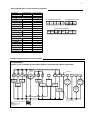
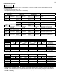
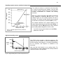
PIR Ready VT76X7 Series
Programmable & Non-Programmable Thermostats
With Humidification & Dehumidification Strategy
For Commercial HVAC Applications
September 1, 2010
Product overview
The VT76x7 PI thermostat family is specifically designed for single stage
and multi-stage control of heating/cooling equipment such as rooftop and
self-contained units with humidifier and/or dehumidifier. The product
features an embedded complete humidity solution with an intuitive, menudriven, backlit LCD display that walks users through the programming
steps, making the process extremely simple. Accurate temperature &
relative humidity control is achieved due to the product’s PI time
proportional control algorithm, which virtually eliminates temperature offset
associated with traditional, differential-based thermostats.
All models contain one digital input, which can be set by the user to
monitor filter status, activate a remote temporary occupancy switch, and/or used as a general purpose service
indicator. The two models contain a SPST auxiliary switch, which can be used to control lighting or disable the
economizer function and a discharge air sensor input.
The thermostats are also compatible with the new Vykon PIR cover accessories. Thermostats equipped with
a PIR cover provide advanced active occupancy logic, which will automatically switch occupancy levels from
Occupied to Stand-By and Unoccupied as required by local activity being present or not. This advanced
occupancy functionality provides advantageous energy savings during occupied hours without sacrificing
occupant comfort. All thermostats can be ordered with or without a factory installed PIR cover ( see ordering
notes below ).
The additional following documentation is available:
• VYKONStat PIR Ready VT76xx Series BACnet Integration Guide
• VYKONStat PIR Ready VT6x7 Series LonWorks Integration Guide
• VYKONStat PIR Application Guide
• VYKONStat PIR Cover Assembly Installation Guide
•
VYKONStat Wireless Controller Application Guide
Models Available
Application
2 Heat / 2 Cool
Model (programmable)
VT7657B5x28(X)
Model (non-programmable)
VT7607B5x28(X)
Ordering Information Notes:
- (X) model number represents available communication options: X=none for Stand-alone, X=B for BACnet MS-TP, X=E for Echelon and X=W for
Wireless
- Thermostats can be ordered with a factory installed PIR cover. Please use (5500) extension instead of the (5028) only extension.: Ex. VT7607B5500E.
- Thermostats ordered without a PIR cover can be retrofitted with a separate PIR accessory cover afterwards when required
Features and benefits
Features
Benefits
• Advanced occupancy functions
⇒ Through the network or smart local occupancy sensing
• Ready for PIR accessory cover
⇒ Fully integrated advanced occupancy functionality with
a PIR accessory cover
⇒ Simplifies installation and reduce installation costs
• Embedded humidification sequence (0-10 Vdc output)
and dehumidification sequence (dry contact)
• Internal embedded RH sensor
• Proportional RH high limit override
• Humidity setpoint reset based on outdoor temperature
•
•
•
•
•
•
•
•
•
PI time proportioning algorithm
1 digital input
Smart fan
Unique configuration key with password protection
6 hour reserve time for clock
Remote outdoor temperature sensor
Auxiliary output
Discharge air humidity sensor ( 0-10 Vdc input )
Intuitive, menu-driven programming (7 day, 2/4 events on programmable models only)
⇒ Eliminates components
⇒ Prevents costly damage due to over-humidification
⇒ Saves energy and prevents window condensation in
colder climates
⇒
⇒
⇒
⇒
⇒
⇒
⇒
⇒
⇒
Increased comfort , accuracy, and energy savings
Adds functionality
Saves energy during night mode
Minimizes parameter tampering
No need to reprogram day/time after power shortage
Increase flexibility and functionality
Can be used for lighting and/or economizer override
Can be used to limit supply RH levels
Can be used for all types of establishments
2
3
Theory of operation
The VT76x7 uses a Viconics proprietary adaptive logic
algorithm to control the space temperature. This
algorithm controls the heating / air conditioning system
to minimize overshoots while still providing comfort. It
provides exceptional accuracy due to its unique PI
time proportioning control algorithm, which virtually
eliminates temperature offset associated with
traditional, differential-based on/off thermostats.
Fig.2 - On/Off mechanical control vs PI electronic control.
Features overview
• 7 day programmable models, 2 or 4 events
• Gas/oil or electric system compatibility for all type
of applications
• Internal RH sensor and remote RH input with
humidification and dehumidification sequence of
operation embedded
• Remote outdoor sensing capability for added
flexibility
- System mode lock out
- Humidity setpoint reset
• High limit input to prevent over-humidification
• Lockable keypads for tamper proofing. No need for
thermostat guards
• Automatic frost protection to prevents costly freeze
damage
• Anti short cycle and minimum on/off run time
protection. Reduces wear and maximizes life span
of mechanical equipment.
• Programmable digital input for added flexibility. The
input can be programmed as the following:
- None: No function will be associated with the
input
- Service: a backlit flashing Service alarm will be
displayed on the thermostat LCD screen when
the input is energized. It can be tied in to the AC
unit control card, which provides an alarm in
case of malfunction.
-
Filter: a backlit flashing Filter alarm will be
displayed on the thermostat LCD screen when the
input is energized. It can be tied to a differential
pressure switch that monitor filters
- Rem NSB: remote NSB timer clock input. Will
disable the internal scheduling of the thermostat.
The scheduling will now be set as per the digital
input. The menu part related to scheduling is
disabled and no longer accessible. It provides low
cost setback operation via occupancy sensor or
from a dry contact
- RemOVR: temporary occupancy contact. Disables
all override menu function of the thermostat. . The
override function is now controlled by a manual
remote momentarily closed contact. When
configured in this mode, the input operates in a
toggle mode.
With this function enabled it is now possible to
toggle between unoccupied & occupied setpoints
for the amount of time set by parameter
(TOccTime) temporary occupancy time.
Fan lock: used in conjunction with a local airflow
sensor connected to the input. Locks out the
thermostat heating and cooling action and displays
a local alarm if no air flow is detected 10 seconds
after the fan ( G terminal ) is energized.
•
•
•
•
•
•
Programmable smart fan operation saves
energy during night mode
Non volatile EEPROM memory prevents loss of
parameters during power shortage
Built in default profile set-up for easier start up
and commissioning
Configurable SPST output relay on
programmable models for lighting, exhaust fan
or fresh air control
6 hour typical reserve time for clock in case of
power loss
0 to 10 Vdc humidification output
- Built in proportional humidity controller
- Proportional humidity high limit when used
with the analog input for supply humidity
- Automatic humidity setpoint reset when
outside air temperature value is used.
4
Installation
•
•
•
•
Remove security screw on the bottom of thermostat cover.
Open up by pulling on the bottom side of thermostat.
Remove Assembly and wiring terminals from sticker. (Fig. 3)
Please note the FCC ID and IC label installed in the cover upon
removal of cover for the wireless products.
A)
12345-
Location:
Should not be installed on an outside wall.
Must be installed away from any heat source.
Should not be installed near an air discharge grill.
Should not be affected by direct sun radiation.
Nothing must restrain vertical air circulation to the thermostat.
B) Installation:
1- Swing open the thermostat PCB to the left by pressing the PCB
locking tabs. (Fig. 4)
2- Pull out cables 6” out of the wall.
3- Wall surface must be flat and clean.
4- Insert cable in the central hole of the base.
5- Align the base and mark the location of the two mounting holes
on the wall. Install proper side of base up.
6- Install anchors in the wall.
7- Insert screws in mounting holes on each side of the base.
(Fig. 4)
8- Gently swing back the circuit board on the base and push on it
until the tabs lock it.
10- Strip each wire 1/4 inch.
11- Insert each wire according to wiring diagram.
13- Gently push back into hole excess wring (Fig. 5)
14- Re-Install wiring terminals in correct location. (Fig. 5)
15- Reinstall the cover (top side first) and gently push back extra
wire length into the hole in the wall.
16- Install security screw.
Fig.3
Fig.4
Re-install terminal blocks
Fig.5
Thermostat assembly
(VT7600B5x28 shown)
•
•
•
•
•
If replacing an old thermostat, label the wires before
removal of the old thermostat.
Electronic controls are static sensitive devices.
Discharge yourself properly before manipulation and
installing the thermostat.
Short circuit or wrong wiring may permanently damage
the thermostat or the equipment.
Anti-short cycling can be set to 0 minutes for equipment
that posses their own anti cycling timer. Do not use that
value unless the equipment is equipped with such
internal timer. Failure to do so can damage the
equipment.
All VT7000 series thermostats are to be used only as
operating controls. Whenever a control failure could
lead to personal injury and/or loss of property, it
becomes the responsibility of the user to add safety
devices and/or alarm system to protect against such
catastrophic failures.
Fig.6
5
Wiring identification & screw terminal arrangement
Part Number
Programmable
VT7657B5x28(X)
Yes
VT7607B5x28(X)
No
Top left terminal block
Y2
Y1
G
RC
C
X
X
X
X
X
X
X
X
X
X
Y2
Y1
G
RC
C
RH W1 W2
8 pole bottom connector
Top right terminal block
RH
W1
W2
3 pole left top connector
5 pole left top connector
X
X
X
X
X
X
DE
HUM AUX HUM DI
HS
S
COM
OS HL
Bottom terminal block
HUM
AUX
DEHUM
DI
HS
SCOM
OS
HL
X
X
X
X
X
X
X
X
X
X
X
X
X
X
X
X
Detailed wiring diagrams for selected models
VT76X7B5X28(X)
2 Heat / 2 Cool / Humidifier & Dehumidifier Outputs / Programmable & Non-Programmable
Jumper J1
See note 1
(previous
page)
Y2
Y1
Cool
Stage 2
G
RC
C
RH
Digital Input
W1
W2
Heat
Stage 1
Fan
Cool
Stage 1
HUM
AU
DeHum
24V
Com
HS
Scom
Auxiliary
Output
24 Vac
T1
Field contact
HL
0-10 Vdc
High Limit
Humidity
Sensor
Remote
Outdoor
Sensor
Dehum
Output
Thermostat internal wiring
System wiring
Jumper J1
OS
0-10 Vdc
Remote
Humidity
Sensor
0-10 Vdc
Heat
Stage 2
DI
6
Wiring notes:
Note 1: If the same power source is used for the heating stages, install jumper across RC & RH. Maximum current is 2.0
amps.
Note 2: If auxiliary output is used to toggle occupancy of the electronic control card inside the equipment, configure the
relay parameter (Aux cont ) to the N.O. setting. A second relay can be added for additional functionality of the
occupancy output.
Note 3: Humidifier output uses a half bridge rectifier. Reference of the control signal is the common of the power supply of
the thermostat. (terminal C)
Note 4: Electromechanical contact are to be used with the digital input. Electronic triacs cannot be used as mean of
switching for the input. The switched leg to the input for the input to activate is terminal C ( common )
Note 5: The transformer of the unit provides power to the thermostat and the additional loads that will be wired to the
thermostat.
Remote humidity sensor accessories
Model no.
VH2020W1028
VH2020D1028
Description
Wall mounted humidity sensor
Duct mounted humidity sensor
VH2020W1028, remote wall mounted room humidity sensor.
This sensor can be used for:
• Remote return or room air humidity sensing with the
sensor mounted on the wall.
Fig.7– VH2020W1028
Remote wall mounted sensor
VH2020D1028, remote duct mounted humidity sensor c/w
junction box.
This sensor can be used for:
• Remote return air humidity sensing with the sensor
mounted on the return air duct.
• Supply air humidity sensor used as a high limit
protection.
Fig.9 – VH2020D1028
Remote duct mounted humidity sensor
Wiring example of remote room humidity sensor:
VT76x7 Series
Thermostat
VT76x7 Series
Thermostat
C
RC
HL
C
24 Vac Power
To Thermostat
RC
VH2020W1000
Remote wiring
OS
1
Common
Scom
2
Power
HS
4
0-10 Vdc
DI
Wiring example of duct humidity sensor:
HL
24 Vac Power
To Thermostat
VH2020D1000
Remote wiring
OS
1
Common
Scom
2
Power
HS
4
0-10 Vdc
DI
Valid for both hight limit sensor (HL) or
main remote humidity sensor (HS) connections
7
User menu flow chart:
NOTE: Prompts may not all be present depending on model selected
MENU
T e mp e r a t
s e t ? Y/ N
If status is:
Unoccupied
Ov e r r i d e
s c h d Y/ N
If status is:
Temporary Occupied Time,
Occupied hold or
Unoccupied hold
Re s u me
s c h d Y/ N
Hu mi d i t y
s e t ? Y/ N
S y s mo d e
s e t ? Y/ N
Off
Heat
Cool
Auto
F a n mo d e
s e t ? Y/ N
On stand-alone
models only
Sc h e d ul e
s e t ? Y/ N
Cl o c k
s e t ? Y/ N
On
Smart
Auto
Hu mi d i f i
s e t ? Y/ N
RH%
RH%
Ex i t
Time
?
Y/ N
Co o l i n g
s e t ? Y/ N
He a t i n g
s e t ? Y/ N
Un o c c CL
s e t ? Y/ N
Un o c c HT
s e t ? Y/ N
° F/ ° C
s e t ? Y/ N
Temperature
Temperature
Temperature
Temperature
°C
°F
Ex i t
?
Y/ N
Ex i t
?
Y/ N
Resume
Occ Hold
Uno Hold
T i me
s e t ? Y/ N
De h u mi d i
s e t ? Y/ N
Sc h e d ul e
h o l d Y/ N
Ex i t
Da y
s e t ? Y/ N
1 2 / 2 4 hr s
s e t ? Y/ N
Day
12 / 24
Ex i t
?
Y/ N
?
Y/ N
Su n d a y
s e t ? Y/ N
Sa t u r da y
s e t ? Y/ N
Fr i day
s e t ? Y/ N
Thur s da y
s e t ? Y/ N
We d n e s d a
s e t ? Y/ N
Tuesday
s e t ? Y/ N
Mo n d a y
s e t ? Y/ N
Oc c u p i e d
d a y ? Y/ N
Oc c u p i e d
d a y ? Y/ N
Oc c u p i e d
d a y ? Y/ N
Oc c u p i e d
d a y ? Y/ N
Oc c u p i e d
d a y ? Y/ N
Oc c u p i e d
d a y ? Y/ N
Oc c u p i e d
d a y ? Y/ N
Oc c u p i e d
12: 00 pm
Oc c u p i e d
12: 00 pm
Oc c u p i e d
12: 00 pm
Oc c u p i e d
12: 00 pm
Oc c u p i e d
12: 00 pm
Oc c u p i e d
12: 00 pm
Oc c u p i e d
12: 00 pm
Time
Time
Time
Time
Time
Time
Time
Un o c c u p
12: 00 pm
Un o c c u p
12: 00 pm
Un o c c u p
12: 00 pm
Un o c c u p
12: 00 pm
Un o c c u p
12: 00 pm
Un o c c u p
12: 00 pm
Un o c c u p
12: 00 pm
Time
Time
Time
Time
Time
Time
Time
8
Programming and status display instructions
1. Status display
The thermostat features a two-line, eight-character display. There is a low-level backlit level that is always active and can only
be seen at night. When left unattended, the thermostat has an auto scrolling display that shows the actual status of the
system. Each item is scrolled one by one with the backlighting off. Pressing any key will cause the backlit to come on.
Sequence of auto-scroll status display:
Room Temp &
Humidity
x.x °C or °F
xx % RH
If humidity display is
enabled
RoomTemp
x.x °C or °F
If humidity display is not
enabled
Clock status
Monday
12.00 AM
System mode
Sys mode
auto
Sys mode
off
Sys mode
heat
Sys mode
cool
Outdoor
temperature
Schedule status
Occupied
Outdoor
x.x °C or°F
Occupied
hold
Unoccup
Unoccup
hold
Override
Alarms
Service
Frost ON
SetClock
Filter
Fan lock
Manual scroll of each menu item is achieved by pressing the Yes (scroll) key repetitively. The last item viewed will be shown on the
display for 30 seconds before returning to automatic scrolling. Temperature is automatically updated when scrolling is held.
Outdoor air temperature display is only enabled when outdoor air temperature sensor is connected or a network value is
received.
• A maximum range status display of 50 °C (122 °F) indicates a shorted sensor. Associated functions, such as mode lockouts
are automatically disabled.
• A minimum range status -40 °C (-40 °F) is not displayed and indicates a opened sensor or a sensor not connected.
Associated functions, such as mode lockouts are automatically disabled.
If alarms are detected, they will automatically be displayed at the end of the status display scroll. During an alarm message
display, the backlit screen will light up at the same time as the message and shut off during the rest of the status display. Two
alarms maximum can appear at any given time. The priority for the alarms is as follows:
Frost ON
SetClock
Service
Filter
Fan lock
Indicates that the heating is energized by the low limit frost protection room temperature setpoint 5.6 °C (42 °F )
Indicates that the clock needs to be reset. There has been a power failure which has lasted longer than 6 hours
Indicates that there is a service alarm as per one of the programmable digital input (DI1 or DI2)
Indicates that the filters are dirty as per one of the programmable digital input (DI1 or DI2)
Indicates that the heating and cooling action are locked out due to a defective fan operation
Three status LEDs on the thermostat cover are used to indicate the status of the fan, a call for heat, or a call for cooling.
•
•
•
When the fan is on, the FAN LED will illuminate.
When heating is on, the HEAT LED will illuminate.
When cooling is on, the COOL LED will illuminate.
Fig.10 – VT7657 and VT7607 cover
9
2. User programming instructions menu
The VT7600 series of thermostat feature an intuitive, menu-driven, backlit LCD display that walks users through the
programming steps, making the programming process extremely simple. This menu is typically accessed by the user to set the
parameters such as temperature and time events, system mode, fan mode, etc.
It is possible to bring up the user menu at any time by depressing the MENU key. The status display automatically resumes
after exiting the user-programming menu.
If the user pauses at any given time during programming, Auto Help text is displayed to help and guide the user through the
usage and programming of the thermostat.
Press yes key to change cooling temperature setpoint
Use the up or down arrow to adjust cooling setpoint
Ex.:
Each of the sections in the menu are accessed and programmed using 5 keys on the thermostat cover.
The priority for the alarms is as follows:
The YES key is used to confirm a selection, to move onto the next menu item and to manually scroll through the
displayed information.
The NO key is used when you do not desire a parameter change, and to advance to the next menu item. Can
also be used to toggle between heating and cooling setpoints.
The MENU key is used to access the Main User Menu or exit the menu.
The down arrow key is used to decrease temperature setpoint and to adjust the desired values when
programming and configuring the thermostat.
The up arrow key is used to increase temperature setpoint and to adjust the desired values when programming
and configuring the thermostat.
When left unattended for 45 seconds, the display will resume automatic status display scrolling.
To turn on the backlit, press any key on the front panel. The backlit display will turn off when the thermostat is left unattended
for 45 seconds
Sequence of user menu:
Override
Resume
Override
schd Y/N
Temperature
setpoints
Temperat
set Y/N
Humidity
setpoints
Humidity
set Y/N
System mode
setting
Fan mode
setting
Schedules
setting
Clock
setting
Sys mode
set Y/N
Fan mode
set Y/N
Schedule
set Y/N
Clock
set Y/N
Appears only in
unoccupied mode
Schedule hold
Schedule
hold Y/N
Appears only on
stand-alone models
Cancel
ovrd Y/N
Appears only in
override mode
There is a default profile set in the thermostat from the factory.
This enables the thermostat to operate as a non-programmable unit in day mode operation at start up.
Programmed default temperature and humidity setpoints:
Programmed default modes:
Occupied cooling setpoint = 24 °C ( 75 °F )
System mode = Auto
Occupied heating setpoint = 22 °C ( 72 °F )
Unoccupied cooling setpoint = 28 °C ( 82 °F )
Fan mode = Smart (for models with a communication module or
programmable stand-alone models)
Fan mode = Auto (for non-programmable stand-alone models)
Unoccupied heating setpoint = 18 °C ( 65 °F )
Programmed default schedules:
Dehumidification setpoint = 70% RH
Monday through Sunday
Humidification setpoint = 50% RH
Occupied time is: 12 00 AM
Fahrenheit scale
Unoccupied time is: 11:59 PM
Setpoint type = permanent
Unoccupied time is: 11:59 PM
There will be a 1 minute unoccupied period every night at 11:59 PM with this default configuration.
10
A) Override an unoccupied period
Override
schd Y/N
This menu will appear only when the thermostat is in unoccupied mode. The unoccupied mode is enabled either by the internal
timer scheduling or by a remote NSB contact via DI.
If DI is configured to operate as a remote temporary override contact, this menu will be disabled.
Answering yes to this prompt will cause the thermostat to go into occupied mode for an amount of time equal to the parameter
“TOccTime” (1 to 12 hours).
B) Resume regular scheduling
Cancel
ovrd Y/N
This menu does not appear in regular operation. It will appear only when the thermostat is in Unoccupied override mode.
Answering “Yes” to this question will cause the thermostat to resume the regular programmed setpoints & scheduling.
C) Temperature setpoints
Permanent setpoint changes
Temperat
set Y/N
This menu permits the adjustment of all permanent temperature setpoints (occupied and unoccupied) as well as the desired
temperature units (°F or °C). Permanent setpoints are written to RAM and EEPROM
Cooling setpoint
Occupied mode
Heating setpoint
Occupied mode
No next →
Heating
set? Y/N
Yes down ↓
Use ▲▼ keys to set value, Yes key to confirm
Use ▲▼
Cooling
Heating
70.0 °F
68.00 °F
To set value
Cooling
set? Y/N
Cooling setpoint
Unoccupied mode
Heating setpoint
Unoccupied mode
°F or °C
display setting
No next →
Yes down ↓
Unocc CL
set? Y/N
No next →
Yes down ↓
Unocc HT
set? Y/N
No next →
Yes down ↓
°F or °C
set? Y/N
No next →
Yes down ↓
Use ▲▼
To set value
Unocc CL
80.0 °F
Use ▲▼
To set value
Unocc HT
60.0 °F
Use ▲▼
To set value
Units
°F
Use ▲▼
To set value
Temporary setpoint changes
Temporary setpoints can be modified through the Up arrow key (▲) and the Down arrow keys (▼).
User will be prompted with the present mode (Heating or Cooling) of the thermostat and its setpoint.
The Up (▲) arrow key will increment the setpoint by 0.5 degree (F or C).
The Down (▼) arrow key will decrement the setpoint by 0.5 degree (F or C).
Press the Yes key to accept the new setpoint.
Local changes to the heating or cooling setpoints made by the user directly using the up or down arrow are temporary.
They will remain effective for the duration specified by ToccTime.
Setpoints will revert back to their default value after internal timer ToccTime expires.
If a permanent change to the setpoints is required, use the Temperat set ? menu
D) Humidity setpoints
Humidity
set Y/N
This menu permits the adjustment of humidification and dehumidification setpoints.
Dehumidification
setpoint
Humidification
setpoint
No next →
Humidifi
set? Y/N
Yes down ↓
Use ▲▼ keys to set value, Yes key to confirm
Use ▲▼
Dehumidi
Humidifi
70 %
50 %
To set value
Dehumidi
set? Y/N
No next →
Yes down ↓
Use ▲▼
To set value
To prevent overlap, a minimum fixed deadband of 5% RH will always prevail between the humidification and dehumidification
setpoints. For example, if the humidification setpoint is 50% RH and the dehumidification setpoint is changed from 70% RH to
45% RH, the humidification setpoint will be modified to 45% RH by the thermostat.
Humidification process
Humidification process will only be allowed when the thermostat is in heating mode (System Mode = Heat or System Mode =
Auto and effective mode at the thermostat is heat). If there is a humidification demand and the fan is OFF, the fan is first turned
ON and the humidifier output is then activated.
Other than having the RH setpoint, the following events can stop the humidification process at any time: RH sensor is out of
range, System Mode is switched to Off or Cool and the System Mode = Auto but the room’s effective mode changes from Heat
to Cool
11
Dehumidification process
If (Dhu LCK) Dehumidification Lockout Functions is set to On (Enabled):
Dehumidification process will only be allowed when the thermostat is in cooling mode (System Mode = Cool or System Mode =
Auto and effective mode at the thermostat is cool). If there is a dehumidification demand and the fan is OFF, the fan is first
turned ON and the dehumidification output is then activated.
Other than having reach the dehumidification setpoint, the following events can stop the dehumidification process at any time:
•
RH sensor is out of range
•
System Mode is switched to Off, Heat or System Mode = Auto and effective mode at the thermostat is Heat
•
The room temp drops below the cooling setpoint minus the deadband value
•
The Outside air temp is below the Dhu OALK parameter
If (Dhu LCK) Dehumidification Lockout Functions is set to Off (Disabled):
Other than having reach the dehumidification setpoint, the following events can stop the dehumidification process at any time:
•
RH sensor is out of range
•
System Mode is switched to Off
•
The Outside air temp is below the Dhu OALK parameter
Dehumidification process is allowed when the thermostat operates in all system mode except Off. If there is a dehumidification
demand. If the fan is OFF, the fan is first turned ON and the dehumidification output is then activated.
There is NO active temperature lockout protection in this mode. If the dehumidification process causes the room temperature to
rise or fall, the thermostat will react by either activating the cooling or heating outputs based on it’s current system mode
settings.
E) System mode setting
Sys mode
set Y/N
This menu is accessed to set system mode operation
Use ▲▼ to set value, Yes key to confirm
Sys mode
auto
Sys mode
cooling
Sys mode
heating
Sys mode
off
Automatic mode
Automatic changeover mode between heating and cooling operation
Cooling mode
Cooling operation mode only
Heating mode
Heating operation mode only
Off mode Normal cooling or heating operation disabled
If enabled in installer parameters, only the automatic heating frost protection at 50 °F ( 10 °C ) is enabled
F) Fan mode setting
Fan mode
set Y/N
This section of the menu is permits the setting of the fan mode operation.
Use ▲▼ to set value, Yes key to confirm
Fan mode
On
On fan mode
Fan is on continuously, even when system mode is OFF.
Fan mode
Auto
Automatic fan mode
Fan cycles on a call for heating or cooling for both occupied & unoccupied periods.
Fan mode
Smart
Smart fan mode
During occupied periods, fan is on continuously. In unoccupied mode, fan cycles on a call for heating or cooling.
This selection is available on all models with a communication module, on all stand-alone programmable models
or if DI1 or DI2 is set to RemNSB on stand-alone non-programmable models
12
G) Schedule set (2 events)
Scheduling can have 2 or 4 events per day. This is set in the configuration menu as per parameter (2/4event )
Schedule
set Y/N
This section of the menu permits the user to set the whether 2 or 4 events is needed. Each day can be tailored to specific
schedules if needed.
• 2 events can be programmed per day.
• Occupied & unoccupied periods can be set for each day.
Monday timer
Schedule set
Tuesday timer
Schedule set
Wednesday timer
Schedule set
No next →
No next →
Tuesday
Wednesda
set? Y/N
set? Y/N
Yes down ↓
Yes down ↓
Yes key to access day scheduling, No key to jump to next day
No next →
No next →
Occupied
Occupied
Occupied
Day? Y/N
Day? Y/N
Day? Y/N
Yes down ↓
Yes down ↓
Yes key to access day scheduling, No key to jump to next day
Yes next →
Copy Y/N
Copy Y/N
Previous
Previous
No down ↓
Yes key to copy previous day, No key to set new time value for each day
Use ▲▼
Use ▲▼
Occupied
Occupied
Occupied
00:00 AM
00:00 AM
00:00 AM
To set value
To set value
Use ▲▼ to set value, Yes key to confirm
Use ▲▼
Use ▲▼
Unoccup
Unoccup
Unoccup
00:00 AM
00:00 AM
00:00 AM
To set value
To set value
Use ▲▼ to set value, Yes key to confirm
Monday
set? Y/N
No next →
Yes down ↓
Selects the day to be programmed or
modified
No next →
Yes down ↓
Yes = Daily schedules will be accessed
No = Unoccupied mode all day
Yes next →
No down ↓
Yes = Will copy previous day schedule
No = Daily schedules will be accessed
Use ▲▼
To set value
Sets Event # 1 Occupied time
Will activate occupied setpoints
Use ▲▼
To set value
Sets Event # 2 Unoccupied time
Will activate unoccupied setpoints
Typical examples of a 2 event office schedule
Ex. #1 Office building closed all weekend
Event
Setpoint
Monday
Tuesday
Wednesday
Thursday
Friday
Saturday
Sunday
Period #1 - Event #1
Occupied
Cool
Heat
72 °F
70 °F
7.00 AM
7.00 AM
7.00 AM
7.00 AM
7.00 AM
12.00 PM *
12.00 PM *
Other days are identical
Note:
Period #1 - Event #2
Unoccupied
Cool
Heat
80 °F
62 °F
6.00 PM
6.00 PM
6.00 PM
6.00 PM
6.00 PM
12.00 PM *
12.00 PM *
12:00 PM = Noon
12:00 AM = Midnight
Daily
Occupancy
Day time only
Day time only
Day time only
Day time only
Day time only
Unoccupied
Unoccupied
* Programming consecutive events to the same time will cause the thermostat to choose the last event as the time at which it
will set its schedule. In the above example, the thermostat will control to the unoccupied set point until 7:00 AM Monday.
Ex. #2 Commercial building which is occupied all weekend
Event
Period #1 - Event #1
Period #1 - Event #2
Occupied
Unoccupied
Cool
Heat
Cool
Heat
Daily
Setpoint
72 °F
70 °F
80 °F
62 °F
Occupancy
8.00 AM
5.00 PM
Day time only
Monday
8.00 AM
5.00 PM
Day time only
Tuesday
8.00 AM
5.00 PM
Day time only
Wednesday
8.00 AM
5.00 PM
Day time only
Thursday
8.00 AM
5.00 PM
Day time only
Friday
12.00 AM **
11.59 PM **
Occupied
Saturday
12.00 AM **
11.59 PM **
Occupied
Sunday
** To program a day as occupied for 24 hours, set that day Occupied time to 12:00 AM and Unoccupied time to 11:59 PM There will be a 1
minute unoccupied period every night at 11:59 PM with this schedule configuration.
13
H) Schedule set (4 events)
Schedule
set Y/N
This section of the menu permits the user to set the whether 2 or 4 events is needed. Each day can be tailored to specific
schedules if needed.
• 4 events can be programmed per day.
• Occupied & Unoccupied periods can be set for each day.
• Programming the 3 rd. & 4 th. events to the same time will cancel the last period.
Monday timer
Schedule set
Tuesday timer
Schedule set
Wednesday timer
Schedule set
No next →
No next →
Tuesday
Wednesda
set? Y/N
set? Y/N
Yes down ↓
Yes down ↓
Yes key to access day scheduling, No key to jump to next day
No next →
No next →
Occupied
Occupied
Occupied
Day? Y/N
Day? Y/N
Day? Y/N
Yes down ↓
Yes down ↓
Yes key to access day scheduling, No key to jump to next day
Yes next →
Copy Y/N
Copy Y/N
Previous
Previous
No down ↓
Yes key to copy previous day, No key to set new time value for each day
Use ▲▼
Use ▲▼
Occupied
Occupied
Occupied
00:00 AM
00:00 AM
00:00 AM
To set value
To set value
Use ▲▼ to set value, Yes key to confirm
Use ▲▼
Use ▲▼
Unoccup
Unoccup
Unoccup
00:00 AM
00:00 AM
00:00 AM
To set value
To set value
Use ▲▼ to set value, Yes key to confirm
Use ▲▼
Use ▲▼
Occupie2
Occupie2
Occupie2
00:00 AM
00:00 AM
00:00 AM
To set value
To set value
Use ▲▼ to set value, Yes key to confirm
Use ▲▼
Use ▲▼
Unoccup2
Unoccup2
Unoccup2
00:00 AM
00:00 AM
00:00 AM
To set value
To set value
Use ▲▼ to set value, Yes key to confirm
Monday
set? Y/N
Other days are identical
No next →
Yes down ↓
Selects the day to be programmed or
modified
No next →
Yes down ↓
Yes = Daily schedules will be accessed
No = Unoccupied mode all day
Yes next →
No down ↓
Yes = Will copy previous day schedule
No = Daily schedules will be accessed
Use ▲▼
To set value
Sets Event # 1 Occupied time
Will activate occupied setpoints
Use ▲▼
To set value
Sets Event # 2 Unoccupied time
Will activate unoccupied setpoints
Use ▲▼
To set value
Sets Event # 3 Occupied time
Will activate occupied setpoints
Use ▲▼
To set value
Sets Event # 4 Unoccupied time
Will activate unoccupied setpoints
Ex. #1 Four event retail establishment schedule
Event
Period 1 - Event 1
Period 1 - Event 2
Period 2 - Event 3
Period 2 - Event 4
Setpoint
Occupied
Unoccupied
Occupied
Unoccupied
Daily
Cool
Heat
Cool
Heat
Cool
Heat
Cool
Heat
Occupancy
72 °F
70 °F
80 °F
62 °F
72 °F
70 °F
80 °F
62 °F
Day time only
7.00 AM
5.00 PM
12.00 PM *
12.00 PM *
Monday
Day time only
7.00
AM
5.00
PM
12.00
PM
*
12.00
PM
*
Tuesday
Day time only
7.00 AM
5.00 PM
12.00 PM *
12.00 PM *
Wednesday
Day/evening time only
7.00 AM
5.00 PM
7.00 PM
10.30 PM
Thursday
Day/evening time only
7.00 AM
5.00 PM
7.00 PM
10.30 PM
Friday
Unoccupied
12.00 PM *
12.00 PM *
12.00 PM *
12.00 PM *
Saturday
Unoccupied
12.00
PM
*
12.00
PM
*
12.00
PM
*
12.00
PM
*
Sunday
* Programming events to the same time will cancel the last period and leave the thermostat in unoccupied mode
Ex. #2 Residential
Event
Period 1 - Event 1
Period 1 - Event 2
Period 2 - Event 3
Period 2 - Event 4
Setpoint
Occupied
Unoccupied
Occupied
Unoccupied
Daily
Cool
Heat
Cool
Heat
Cool
Heat
Cool
Heat
Occupancy
72 °F
70 °F
80 °F
62 °F
72 °F
70 °F
80 °F
62 °F
Day/evening time only
Monday
6:00 AM
8:00 AM
4:00 PM
10:00 PM
Day/evening time only
Tuesday
6:00 AM
8:00 AM
4:00 PM
10:00 PM
Day/evening time only
Wednesday
6:00 AM
8:00 AM
4:00 PM
10:00 PM
Day/evening time only
Thursday
6:00 AM
8:00 AM
4:00 PM
10:00 PM
Day/evening time only
Friday
6:00 AM
8:00 AM
4:00 PM
11:30 PM
Day time only
Saturday
8:00 AM *
8:00 AM *
8:00 AM *
11:59 PM *
Occupied all day
Sunday
12:00 AM *
12:00 AM *
12:00 AM *
11:59 PM *
* Programming consecutive events to the same time will cause the thermostat to choose the last event as the time at which it will
set its schedule. In the above example for Saturday, the thermostat will control to the occupied set point from 8:00 AM until
11:59 PM. Since it is desired to be in occupied mode throughout the night, then it is necessary to program the first event on
Sunday at 12:00 AM. The thermostat will force a one minute unoccupied period for a one minute period (between 11:59 PM and
12:00 AM on Saturday).
14
I) Clock/Day Settings
Clock
set Y/N
This section of the menu permits the user to set the time and day.
Time setting
Time
set? Y/N
Time
0:00
No next →
Yes down ↓
Use ▲▼
To set value
Day setting
Day
set? Y/N
Day
Monday
No next →
Yes down ↓
Use ▲▼
To set value
Time format setting
12/24hrs
set? Y/N
12/24hrs
12 hrs
No = exit
Yes down ↓
Use ▲▼
To set value
J) Schedule hold
Schedule
hold Y/N
This menu
•
•
•
•
•
This menu will only appear on stand-alone thermostat, e.i. without a BACnet / Echelon module.
This section of the menu permits the user to set a permanent schedule hold, which bypasses the internal
thermostat scheduling.
The permanent schedule hold function is typically used for non-scheduled events that extend for various periods
of time.
Enabling a permanent occupied or permanent unoccupied schedule hold will cancel any active override.
The use of temporary setpoints during permanent hold is permitted. The duration of the temporary setpoint is as
set per the TOccTime parameter. Ex. 3 hours
Use ▲▼ to set value, Yes key to confirm
Schedule
resume
Resume regular scheduling cancels the permanent hold and re-enables the regular
programming as set per internal scheduling or as per remote NSB via one of the DI’s
configured as remote NSB.
This action can also by accomplished by using the Resume menu.
Any temporary setpoint that are active will be left active for the duration of the period as set
per the TOccTime parameter.
Schedule
occ hold
Hold permanent occupied forces the thermostat into a permanent occupied mode using the
occupied setpoints. All timed scheduling functions are by-passed.
The PERMANENT OCCUPIED status will appear in the automatic status scroll. To resume
to regular scheduling, user must scroll to the Schedule Hold menu and select the Schedule
resume option..
Schedule
uno hold
Hold permanent unoccupied forces the thermostat into a permanent unoccupied mode
using the unoccupied setpoints. All timed scheduling functions are by-passed.
The PERMANENT UNOCCUPIED status will appear in the automatic status scroll. To
resume to regular scheduling, user must scroll to the Schedule Hold menu and select the
Schedule resume option..
15
Installer configuration parameter menu
-
Configuration can be done through the network or locally at the thermostat.
-
To enter configuration, press and hold the middle button “Menu” for 8 seconds
-
If a password lockout is active, “Password” is prompted. Enter password value using the “up” and “down”
arrows and press “Yes” to gain access to all configuration properties of the thermostat. A wrong password
entered will prevent local access to the configuration menu.
-
Once in the configuration menu, press the “No” button repetitively to scroll between all the available
parameters.
-
When the desired parameter is displayed, press “Yes” to adjust it to the desired value using “up” and
“down” arrows. Once set, press “Yes” to scroll to the next parameter.
Configuration
parameters
Pswrd
Significance
Default value
Configuration parameters menu access This parameter sets a protective access password to
password
prevent unauthorized access to the configuration menu
parameters. A default value of “0” will not prompt a
password or lock the access to the configuration menu.
Default value = 0 ( no password
prompted )
Com addr
Thermostat networking address
Default value = 254
Range is: 0 to 254
PAN ID
Adjustments
Personal Area Network Identification
Default value = 0
Range is: 0 to 500
Range is: 0 to 1000
Conditional parameter to BACnet MS-TP models
(VT76xxX5x28B)
Conditional parameter to Wireless models
(VT76xxX5x28W)
This parameter will only appear when a BACnet or
wireless network adapter is present. If the thermostat is
installed as a stand-alone unit or with an Echelon
adapter, this parameter will not be used or displayed
-
For BACnet MS-TP models valid range to use is
from 1 to 127. Default value of 254 disables BACnet
communication for the thermostat.
-
For wireless models valid range is 0 to 254 with a
maximum of 30 thermostat per VWG
Conditional parameter to Wireless models
(VT76xxX5x28W)
This parameter will only appear when a wireless network
adapter is present. If the thermostat is installed as a standalone unit or with a BACnet or Echelon adapter, this parameter
will not be used or displayed
This parameter (Personal Area Network Identification) is used
to link specific thermostats to a single specific Vykon JACE
with wireless network adapter. For every thermostat reporting
to a JACE (maximum of 30 wireless thermostats), be sure you
set the SAME PAN ID value both at the JACE and the
thermostat(s).
The default value of 0 is NOT a valid PAN ID. The valid range
of available PAN ID is from 1 to 500
16
Channel
Channel selection
Conditional parameter to Wireless models
(VT76xxX5x28W)
Default value = 10
This parameter will only appear when a wireless network
adapter is present. If the thermostat is installed as a standalone unit or with a BACnet or Echelon adapter, this parameter
will not be used or displayed
Range is: 10 to 26
This parameter (Channel) is used to link specific thermostats to
a specific Vykon JACE with wireless network adapter. For
every thermostat reporting to a JACE (maximum of 30 wireless
thermostats ), be sure you set the SAME channel value both at
the JACE and the thermostat(s).
Vykon recommends using only the 2 last channels ( 252575MHz and 26-2580MHz )
The default value of 10 is NOT a valid channel. The valid range
of available channel is from 11 to 26
%RH disp
DI
Local RH Display
Default value = Off
Digital input no.1 configuration
Open contact input = function not
energized
Closed contact input = function
energized
Default value = None
MenuScro
Menu scroll
Default value = On = Scroll active
Enables the display of humidity below the room
temperature on the display
On = Display %RH
Off = No display of %RH
None, No function will be associated with the input
Rem NSB, remote NSB timer clock input. Will disable
the internal scheduling of the thermostat. The scheduling
will now be set as per the digital input. The time is still
displayed as information, but the menu part related to
scheduling is disabled and no longer accessible.
Open contact = occupied setpoints
Closed contacts = unoccupied setpoints
RemOVR Temporary override remote contact. Disables
all override menu function of the thermostat. The
override function is now controlled by a manual remote
momentarily closed contact. When configured in this
mode, the input operates in a toggle mode. With this
function enabled it is now possible to toggle between
unoccupied & occupied setpoints for the amount of time
set by parameter (TOccTime) temporary occupancy
time. When Override is enabled, an Override status
message will be displayed
Filter, a back-lit flashing Filter alarm will be displayed
on the thermostat LCD screen when the input is
energized
Service, a back-lit flashing Service alarm will be
displayed on the thermostat LCD screen when the input
is energized
Fan lock, a back-lit flashing Fan lock alarm will be
displayed on the thermostat LCD screen when the input
is not energized. Used in conjunction with a local airflow
sensor connected to the input. Locks out the thermostat
heating and cooling action if no airflow is detected 10
seconds after the fan ( G terminal ) is energized.
Open contact = no airflow
Closed contacts = airflow present
Removes the scrolling display and only present the room
temperature/humidity to the user. With this option
enabled, no status is given of mode, schedule and
outdoor temperature.
On = Scroll active
Off = Scroll not active
17
Lockout
Keypad lockout levels
0 = No lock
1 = Low level
2 = High level
Default value = 0 No lock
Level
0
1
2
Pwr del
Resume/
Override
scheduling
Permanent
Temporary
Occupied and
setpoints
Unoccupied
using arrows
Setpoints
Humidity
Setpoints
System mode
setting
Fan mode
setting
Schedules
setting
Clock setting
Permanent
hold
Resume
sched Y/N
Temperat
set Y/N
Up key (▲)
Down key (▼)
Humidity
set Y/N
Sys mode
set Y/N
Fan mode
set Y/N
Schedule
set Y/N
Clock
set Y/N
Schedule
hold Y/N
Yes access
Yes access
No access
Yes access
No access
No access
Yes access
Yes access
No access
Yes access
No Access
No Access
Yes access
No access
No access
Yes access
No access
No access
Yes access
No access
No access
Yes access
Yes access
Yes access
Yes access
No access
No access
Power-up delay
Default value = 10 seconds
Frost pr
Heat max
Frost protection enabled
Default value = Off
On heat pump models the system mode
will be forced to EMERGENCY mode if
frost protection is activated
Maximum heating setpoint limit
Default value = 90 °F ( 32 °C )
Cool min
Minimum cooling setpoint limit
Default value = 54 °F ( 12 °C )
Pband
Proportional Band setting
Default value = 2.0 °F ( 0.6 °C )
On initial power up of the thermostat (each time 24 Vac
power supply is removed & re-applied) there is a delay
before any operation is authorized (fan, cooling or
heating). This can be used to sequence start up multiple
units / thermostat in one location.
10 to 120 seconds
Off: no room frost protection
On: room frost protection enabled in all system mode at:
42 °F ( 5.6 °C )
Frost protection is enabled even in system Off mode
Off or On
Maximum occupied & unoccupied heating setpoint
adjustment. Heating setpoint range is:
40 to 90 °F ( 4.5 to 32.0 °C )
Minimum occupied & unoccupied cooling setpoint
adjustment. Cooling setpoint range is:
54 to 100 °F ( 12.0 to 37.5 °C )
Adjust the proportional band used by the thermostat PI
control loop.
Warning. Please note that the default value of 2.0 °F ( 0.6
°C ) gives satisfactory operation in most normal
installation cases. The use of a superior proportional band
different than the factory one is normally warranted in
applications where the thermostat location is problematic
and leads to unwanted cycling of the unit. A typical
example is a wall mounted unit where the thermostat is
installed between the return and supply air feeds and is
directly influenced by the supply air stream of the unit.
Value
2
3
4
5
6
7
8
Anticycle
Minimum on/off operation time for stages
Default value = 2 minutes
Anti-short cycling can be set to 0 minutes
for equipment that posses their own anti
cycling timer. Do not use that value
unless the equipment is equipped with
such internal timer. Failure to do so can
damage the equipment.
F scale
Pband
2F
3F
4F
5F
6F
7F
8F
C scale
Pband
0.6 C
1.2 C
1.7 C
2.2 C
2.8 C
3.3 C
3.9 C
Minimum On/Off operation time of cooling & heating
stages.
IMPORTANT, anti-short cycling can be set to 0 minutes
for equipment that posses their own anti cycling timer. Do
not use this value unless the equipment is equipped with
such internal timer. Failure to do so can damage the
equipment.
0, 1, 2, 3, 4 & 5 minutes
18
Heat cph
Cool cph
Deadband
Fan cont
Fan del
TOccTime
Cal RS
Cal OS
H stage
Will set the maximum number of heating stage cycles per
hour under normal control operation. It represents the
maximum number of cycles that the equipment will turn ON
and OFF in one hour.
Note that a higher C.P.H will represent a higher accuracy of
control at the expense of wearing mechanical components
faster.
3, 4, 5, 6,7 & 8 C.P.H.
Will set the maximum number of cooling stage cycles per
Cooling stages cycles per hour
hour under normal control operation. It represents the
Default value = 4 C.P.H.
maximum number of cycles that the equipment will turned on
and off in one hour.
Note that a higher C.P.H will represent a higher accuracy of
control at the expense of wearing mechanical components
faster.
3 or 4 C.P.H.
Minimum deadband
Minimum deadband value between the heating and cooling
Default value = 2.0 °F ( 1.1 °C )
setpoints. If modified, it will be applied only when any of the
setpoints are modified.
2, 3 or 4 °F ( 1.0 to 2.0 °C )
Fan control in heating mode.
Fan control
When selecting On; the thermostat in all cases will always
Default value = On
control the fan (terminal G).
Valid for On or Auto fan mode
When selecting Off; the fan ( terminal G ), when heating
stages ( terminals W1 & W2 ) are solicited, will not be
energized. The fan in this case will be controlled by the
equipment fan limit control.
Valid only for Auto fan mode. On fan mode will leave the fan
always on.
On or Off
Fan delay
Fan delay extends fan operation by 60 seconds after the call
Default value = Off
for heating or cooling ends.
Valid only for Auto fan mode. “On” fan mode will leave the fan
always on.
Off or On
Temporary occupancy time
Temporary occupancy time with occupied mode setpoints
Default value = 3 hours
when override function is enabled
When the thermostat is in unoccupied mode, function is
enabled with either the menu or DI1 or DI2 configured as
remote override input.
0,1, 2, 3, 4, 5, 6, 7, 8, 9, 10, 11 & 12 hours
Offset that can be added/subtracted to actual displayed room
Room air temperature sensor
temperature
calibration
± 5.0 °F ( ± 2.5 °C )
Default value = 0.0 °F or °C
Offset that can be added/subtracted to actual displayed
Outside air temperature sensor
outside air temperature
calibration
± 5.0 °F ( ± 2.5 °C )
Default value = 0.0 °F or °C
Number of heating stages. Applicable Will revert the operation of 2 stages thermostat to single
stage operation only when the second heating step is not
to 2 stage models only
needed.
Default value = 2 stages
1 or 2 stages
Heating stages cycles per hour
Default value = 4 C.P.H.
19
C stage
Number of cooling stages
2 stages model only
Default value = 2 stages
Will revert the operation of 2 stage thermostat to single stage
operation only when the second cooling step is not needed.
1 or 2 stages
H lock
Outside air temperature heating
lockout
Default value = 120 °F ( 49 °C )
C lock
Outside air temperature mechanical
cooling lockout.
Default value = -40 °F ( -40 °C )
Disables heating stage operation based on outdoor air
temperature.
Function will only be enabled if OS ( outside air temperature
sensor ) is connected.
From -15 °F up to 120 °F ( -26 °C up to 49 °C )
Disables cooling stage operation based on outdoor air
temperature.
On economizer model, free cooling will not be disabled by
this function.
Function will only be enabled if OS ( outside air temperature
sensor ) is connected.
From -40 °F up to 95 °F ( -40 °C up to 35 °C )
Time delay between the moment where the thermostat
toggles from occupied to unoccupied after the last movement
has been detected by the PIR.
Unocc TM
Unoccupied Timer value
Default 0.5 hours
Range is: 0.5 to 24.0 hours in 0.5 hour increments
2/4event
Number of events configuration
2 events, will set up programming for the following
Default value = 2 event
Event 1 is for Occupied setpoints
For scheduling model only VT7657B1028B
Event 2 is for Unoccupied setpoints
4 events, will set up programming for the following
Event 1 is for Occupied setpoints
Event 2 is for Unoccupied setpoints
Event 3 is for Occupied setpoints
Event 4 is for Unoccupied setpoints
Aux cont
Auxiliary contact configuration
Default value = N.O. normally open
This contact can be used to energize peripheral devices
such as: lighting equipment, exhaust fans, economizers, etc.
This contact will operate in parallel with the internal
occupied/unoccupied schedule of the thermostat or the
remote NSB contact if DI is used.
When the system is in OFF mode, the contact will remain in
its unoccupied status independently of the occupied /
unoccupied schedule.
Contact
Contact unoccupied
Configured
occupied
status
status
N.O.
Closed
Opened
N.C.
opened
Closed
20
Prog rec
Progressive recovery enabled
Default value = Off
Progressive recovery is
automatically disabled if DI is
configured as Remote NSB
For scheduling model only VT7657B1028B
Off, = no progressive recovery
The programmed occupied schedule time is the time at
which the system will restart.
On, = progressive recovery active.
The programmed occupied schedule time is the time at
which the desired occupied temperature will be attained.
The thermostat will automatically optimize the equipment
start time.
In any case, the latest a system will restart is 10 minutes
prior to the occupied period time.
RH LT
RH HT
HL Sp
Dhu OALK
Dhu LCK
DehuHyst
Minimum outside air temperature for RH setpoint reset.
Only valid if an outdoor air sensor is connected at the
thermostat or a network value is transmitted to the
thermostat. See RH HT & RE Sp.
From –40°F up to 15°F (-40°C to –9.5°C)
Maximum outdoor air temperature for RH setpoint reset.
Reset RH higher outside
Only valid if an outdoor air sensor is connected at the
temperature setpoint
thermostat or a network value is transmitted to the
Default value = 32°F (0°C)
thermostat. See RH LT & RE Sp
From 20°F up to 55°F (-6.5°C to 13°C)
RH High limit setpoint
High humidity limit in the supply.
Default value = 85% RH
Only valid if a 0-10 Vdc sensor is connected at the
thermostat – otherwise this feature is disabled automatically.
From 50% RH up to 90% RH
Outside air temperature under which the dehumidification
Dehumidification outside air
sequence is disabled.
temperature lockout
Only valid if an outdoor air sensor is connected at the
Default value = 32°F (0°C)
thermostat or a network value is transmitted to the
thermostat.
From –40°F up to 122°F (-40°C to 50°C)
Dehumidification Lockout Functions Enables or disables the lockout functions for the
Default value = On
dehumidification control process of the output.
On: will restrict the dehumidification process based on the
following:
- System mode = Needs to be Cool or Auto ( currently
operating in cooling only )
- Low ambient room temperature protection enabled
Off: will not restrict the dehumidification process:
- System mode = Needs to be Cool, Heat or Auto
- There is no ambient room temperature protection
enabled
Dehumidification hysterisys
Dehumidification control hysterisys.
Default value = 5% RH
Used only if dehumidification sequence is enabled.
From 2% RH up to 20% RH
Reset RH lower outside
temperature setpoint
Default value = -20°F (-29°C)
21
RE Sp
Reset humidity setpoint
Default value = 20% RH
The RH setpoint will be reset from the user setpoint
to this value when the RH LT outside air
temperature value is reached.
Only valid if an outdoor air sensor is connected at
the thermostat or a network value is transmitted to
the thermostat. See RH LT & RE HT.
From 10% RH up to 90% RH
RH cal
Humidity sensor calibration
Offset that can be added/subtracted to actual
displayed humidity by ± 15.0 %RH.
Default value = 0 %RH
This calibration applies to the internal humidity
sensor if no remote humidity sensor is connected.
This calibration applies to the remote humidity
sensor when one is connected.
From –15% RH up to 15% RH
Display
HL
Display the high limit sensor value
Used as diagnostic / service help to troubleshoot
and diagnose sensor / humidifier operation
Note:
When the outside air sensor is not connected or is shorted, the thermostat bypasses:
• The heating lockout
• The cooling lockout
• The dehumidification lockout
• The humidity setpoint reset
22
Humidity setpoint reset by outside air temperature
45%
If an outdoor air sensor is connected at the thermostat
or a value is received from the network, it can be used
to reset the humidity setpoint during the cold season to
minimize condensation on windows and building
structures.
RH Set = 45%
%RH Setpoint
40%
RH HT = 32°F
35%
When the outdoor temperature falls below the selected
high temperature, parameter RH HT (32°F in the
example Figure 8), the humidity setpoint will start to
decrease. The lowest humidity setpoint will be reached
at selected low temperature, parameter RH LT (-20°F).
30%
25%
RE Sp = 20%
20%
RH LT = -20°F
-40°F -20°F 0°F 20°F
Outside Air Temp.
40°F
Fig.11 – Humidity setpoint reset by outside air
temperature
The setpoint decrease from original setpoint to the
lowest setpoint determined by the parameter RE Sp. In
the example, Figure 8, RE Sp was set to 20%, therefore
the humidity setpoint dropped from 45% to 20%.
If you don’t want to use this feature, set the RE Sp
parameter to 90% RH.
High limit humidity sensor
100%
Control
Output
Level
The VT76x7 series includes a high limit sequence. This
allows the use of a remote 0 to 10 Vdc humidity sensor to
limit the humidity in the supply air. If no sensor is detected at
the HL connector, this sequence is disabled at the
thermostat.
50%
0%
85%
Maximum Supply Humidity
Fig.12 – High humidity limit vs Control output level curve
Note: this high limit function is not a safety device. For
critical situations, provide installation with normal protections
required to ensure a safe operation.
23
Troubleshooting guide
Symptom
No display on the
thermostat
Possible Cause
Absent or incorrect supply
voltage
Overloaded power
transformer
Corrective Action
1. Check power supply voltage between C & RC to be
from 19-30 Vac
2. Check for tripped fuse or circuit breaker
Verify that the transformer used is powerful enough
(enough VA’s) to supply all controlled devices
including the thermostat
Keyboard menu does
not access all functions
Keyboard locked
Change configuration parameter LOCKOUT to value
“0” to access all levels of the menu
Temperature setpoints
revert to original value
after a certain time
period
Temporary setpoint option
selected
1. The thermostat needs to be in Permanent setpoint
mode for the new setpoint to be kept and memory
and used all the time
2. Go to the Set temperature menu.
3. The last prompt is setpoint type. Set it to
Permanent setpoint
Thermostat will not call
for heating
Wrong mode selected
Thermostat in Unoccupied
mode
Anticycle delay active
Select heating mode
Select Occupied Hold in Schedule hold or Override to
force the thermostat Occupied heating setpoint
Wait, the anticycling period will end and the
equipment will start
Raise the Heating setpoint
1. Mode is locked out based on outside air
temperature
2. Change configuration parameter H Lock to value
120 °F ( 49 °C ) to by-pass lockout
1. Start the Fan by forcing the Fan ON mode
2. Put a jumper across terminals RH & W1. The
heating should come ON. If it does not, verify
wiring and check if a jumper is required between
RC & RH
Heating setpoint is satisfied
Heating lockout attained
Wiring error
24
Symptom
Thermostat will not call
for cooling
Possible Cause
Wrong mode selected
Thermostat in Unoccupied
mode
Anticycle delay active
Cooling setpoint is satisfied
Cooling lockout attained
Wiring error
Corrective Action
Select cooling mode
Select Occupied Hold in Schedule hold or Override to
force the thermostat Occupied cooling setpoint
Wait, the anticycling period will end and the
equipment will start
Lower the cooling setpoint
1. Mode is locked out based on outside air
temperature
2. Change configuration parameter C Lock to value 40 °F ( -40 °C ) to by-pass lockout
1. Start the Fan by forcing the Fan ON mode
2. Put a jumper across terminals RC & Y1. The
cooling should come ON. If it does not, verify wiring
The thermostat will not
turn on the fan
Wrong mode selected
Wiring error
1. Start the Fan by forcing the Fan ON mode
2. Put a jumper across terminals RC & G. The fan
should come ON. If it does not, verify wiring
Digital display shows
missing digits or erratic
segments
Defective display
Replace thermostat
Thermostat will not call
for humidification
RH sensor is out of range
Verify the remote RH sensor or the internal RH
sensor
Change the system mode parameter to heat
Wait: when a heating demand will occur at the
thermostat, humidification will resume
Thermostat will not call
for dehumidification
System Mode in Cool or Off
System Mode in Auto but a
cooling demand at the
thermostat
High limit sensor is controlling
the humidifier output by
forcing it to 0%
RH sensor is out of range
System Mode in Heat or Off
System Mode in Auto but a
heating demand at the
thermostat
Outside air temperature is
below the Dhu OALK
parameter
Wait: when the supply humidity will drop below the
high limit setpoint, humidification will resume.
Verify the remote RH sensor or the internal RH
sensor
Change the system mode parameter to cool
Wait: when a cooling demand will occur at the
thermostat, dehumidification will resume
Change the Dhu OALK parameter to a value that will
enable the dehumidification, if desired.
25
Specifications
Thermostat power requirements:
19-30 Vac 50 or 60 Hz; 2 VA ( RC & C ) Class 2
RC to RH jumper 2.0 Amps 48 VA maximum
Operating conditions: 0 °C to 50 °C ( 32 °F to 122 °F )
0% to 95% R.H. non-condensing
Storage conditions: -30 °C to 50 °C ( -22 °F to 122 °F )
0% to 95% R.H. non-condensing
Temperature sensor: Local 10 K NTC thermistor
Resolution: Temperature: ± 0.1 °C (± 0.2 °F)
Humidity: ± 0.1%
Control accuracy: Temp: ± 0.5 ° C ( ± 0.9 °F ) @ 21 °C ( 70 °F ) typ. calibrated
Humidity: ± 5% RH from 20 to 0% RH at 50 to 90°F (10 to 32°C)
Humidification setpoint range: 10% RH to 90% RH
Dehumidification setpoint range: 15% RH to 95% RH
Occupied and unoccupied setpoint range cooling: 12.0 to 37.5 °C ( 54 to 100 °F )
Occupied and unoccupied setpoint range heating: 4.5 °C to 32 °C ( 40 °F to 90 °F )
Room and outdoor air temperature range -40 °C to 50 °C ( -40 °F to 122 °F )
Proportional band for room temperature control: Factory set, heating and cooling at: 1.1°C ( 2.0°F )
Digital input: Relay dry contact only across C terminal to DI1
Analog high limit and remote humidity inputs 0 to 10 Vdc into 10KΩ input load
Contact output rating: Each relay output: ( Y1, Y2, G, W1, W2 & AU )
30 Vac, 1 Amp. maximum
30 Vac, 3 Amp. in-rush
Humidification analog output rating: 0 to 10 Vdc into 2KΩ resistance min.
Humidification analog output accuracy: ± 3% typical
Wire gauge 18 gauge maximum, 22 gauge recommended
Dimensions: 4.94” x 3.38” x 1.13”
Approximate shipping weight: 0.75 lb ( 0.34 kg )
Agency Approvals all models: UL: UL 873 (US) and CSA C22.2 No. 24 (Canada), File E27734 with
CCN XAPX (US) and XAPX7 (Canada)
Industry Canada: ICES-003 (Canada)
Agency Approvals all models FCC: Compliant to CFR 47, Part 15, Subpart B, Class A (US)
CE: EMC Directive 89/336/EEC (Europe Union)
C-Tick: AS/NZS CISPR 22 Compliant (Australia / New Zealand)
Supplier Code Number N10696
Agency Approvals Wireless models FCC: Compliant to: Part 15, Subpart C
THIS DEVICE COMPLIES WITH PART 15 OF THE FCC RULES. OPERATION IS SUBJECT TO THE FOLLOWING TWO
CONDITIONS: (1) THIS DEVICE MAY NOT CAUSE HARMFUL INTERFERENCE, AND (2) THIS DEVICE MUST ACCEPT ANY
INTERFERENCE RECEIVED, INCLUDING INTERFERENCE THAT MAY CAUSE UNDESIRED OPERATION.
Drawing & dimensions
Important Notice
Fig.13 – Thermostat dimensions
All VT7600 series controls are
for use as operating controls
only and are not safety
devices. These
instruments have undergone rigorous
tests and verifications prior to shipment to
ensure proper and reliable operation in
the field. Whenever a control failure could
lead to personal injury and/or loss of
property, it becomes the responsibility of
the user / installer / electrical system
designer to incorporate safety devices (
such as relays, flow switch, thermal
protections, etc…) and/or alarm system to
protect the entire system against such
catastrophic failures. Tampering of the
devices or miss application of the device
will void warranty.
Vykon and WEEE
The Waste Electrical and Electronic Equipment (WEEE) mark applies only to countries within the European Union (EU) and Norway.
Electric/Electronic devices are labeled in accordance with European Directive 2002/96/EC concerning waste electrical and electronic
equipment (WEEE). The Directive determines the framework for the return and recycling of used Electric/Electronic devices at the end of
life within and throughout the European Union (EU). This label is applied to various products to indicate the product is not to be thrown
away, but rather be reclaimed upon the end of the products useful life per this directive.
Users of electric and electronic equipment with the WEEE marking per annex IV of the WEEE Directive must not dispose of end of life
Electric/Electronic waste as unsorted municipal waste, but rather use the collection framework available to them for the return, recycle and
recovery of WEEE and minimize the environmental impact of Electric/Electronic waste due to the presence of hazardous substance.
For additional information please go to: www.Vykon.com