1
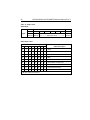
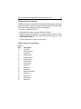
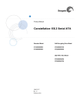
○
○
○
○
○
○
○
○
○
○
○
○
○
○
○
○
○
○
○
○
○
○
○
○
○
○
○
○
○
○
○
○
○
○
○
○
○
○
○
○
○
○
○
○
○
○
○
○
○
○
○
○
○
○
○
○
○
○
○
○
○
○
○
○
○
○
○
○
○
○
○
○
Elite Disc Drive
○
○
○
○
○
○
○
○
○
○
○
○
ST43401N/ND
○
○
○
○
○
○
○
○
○
○
○
○
○
○
○
○
○
○
○
○
○
○
○
○
○
○
○
○
○
○
○
○
○
○
○
○
○
○
○
○
○
○
ST43402ND
○
○
○
○
○
○
○
○
○
○
○
○
○
○
○
○
○
○
○
○
○
○
○
○
○
○
○
○
○
○
○
○
○
○
○
○
○
○
○
○
○
○
○
○
○
○
○
○
○
○
○
○
○
○
○
○
○
○
○
○
○
○
○
○
○
○
○
○
○
○
○
○
○
○
○
○
○
○
○
○
○
○
○
○
○
○
○
○
○
○
○
○
○
○
○
○
○
○
○
○
○
○
○
○
○
○
○
○
○
○
○
Reference Manual
○
○
○
○
○
○
○
○
○
○
○
○
○
○
○
Contents
Preface ...................................................................................................
Electrostatic discharge protection ...........................................................
Important safety information and precautions .........................................
Technical support services .....................................................................
Section 1. General maintenance information .........................................
Section 2. Planning the system ..............................................................
Section 3. Interface functions ................................................................
iii
iii
iv
vi
1
5
19
© 1994 Seagate Technology, Inc. All rights reserved
Publication number: 83327730, Rev. C
December 1994
Seagate®, Seagate Technology®, and the Seagate logo are registered
trademarks of Seagate Technology, Inc. Elite™, SeaFAX™, SeaFONE™,
SeaTDD™, and SeaBOARD™ are trademarks of Seagate Technology, Inc.
Other product names are registered trademarks or trademarks of their
owners.
Seagate reserves the right to change, without notice, product offerings or
specifications. No part of this publication may be reproduced in any form
without written permission from Seagate Technology, Inc.
ST43401N/ND and ST43402ND Reference Manual, Rev. C
iii
Preface
This is a reference manual for users of Seagate® ST43401N/ND and
ST43402ND Elite™ disc drives employing the SCSI interface. It supplements
the information presented in the user’s manual (publication 83327720). It is
intended to aid engineers who design subsystems using the drive and
customer engineers who install and check out the drive. This manual should
be used in conjunction with the user’s manual.
Electrostatic discharge protection
Caution. Removal of circuit boards by personnel not performing depot repair
will damage components and may void the warranty.
All drive electronic assemblies are sensitive to static electricity due to the
electrostatically sensitive devices used within the drive circuitry. Although
some devices such as metal-oxide semiconductors are extremely sensitive,
all semiconductors, as well as some resistors and capacitors, may be
damaged or degraded by exposure to static electricity.
Electrostatic damage to electronic devices may be caused by the direct
discharge of a charged conductor, or by exposure to the static fields surrounding charged objects. To avoid damaging drive electronic assemblies, service
personnel must observe the following precautions when servicing the drive:
• Ground yourself to the drive whenever the drive electronics are or will be
exposed. Connect yourself to ground with a wrist strap (Seagate part
number 12263496). Connection may be made to any grounded metal
assembly. As a general rule, remember that you and the drive electronics
must all be grounded to avoid potentially damaging static discharges.
• Turn off power before removing or installing the DC power cable.
• Do not remove any circuit boards from the drive.
• Never use an ohmmeter on any circuit boards.
iv
ST43401N/ND and ST43402ND Reference Manual, Rev. C
Important safety information and precautions
Caution. Use forced-air ventilation when bench-testing the drive to ensure
proper cooling of drive components.
Use proper safety and repair techniques for safe, reliable operation of this unit.
Service should be done only by qualified persons. We recommend the
procedures in this manual as effective ways of servicing the unit. Some
procedures require the use of special tools. For proper maintenance and
safety, you must use these tools as recommended.
The procedures in this manual contain warnings and cautions that must be
carefully read and followed to minimize or eliminate the risk of personal injury.
The warnings point out conditions or practices that may endanger you or
others. The cautions point out conditions or practices that may damage the
unit, possibly making it unsafe for use.
You must also understand that these warnings and cautions are not exhaustive. We cannot possibly know, evaluate, and advise you of all the ways in
which maintenance might be performed or the possible risk of each technique.
Consequently, we have not completed any such broad evaluation. If you use
a non-approved procedure or tool, first ensure that the method you choose will
not risk either your safety or unit performance.
Always observe the following warnings and precautions:
•
•
•
•
Perform all maintenance by following the procedures in this manual.
Follow all cautions and warnings in the procedures.
Use sound safety practices when operating or repairing the unit.
Use caution when troubleshooting a unit that has voltages present. Remove
power from the unit before servicing it.
• Wear safety shoes when removing or replacing heavy parts.
• Ensure that the internal temperature of the rack or cabinet will not exceed
the limits defined for the drive when the drive is mounted in an equipment
rack or cabinet. When units are stacked vertically, pay special attention to
the top where temperatures are usually highest.
• Follow the precautions listed under “Electrostatic discharge protection”
above.
ST43401N/ND and ST43402ND Reference Manual, Rev. C
v
• Do not remove any circuit boards from the drive chassis. Return the entire
drive for depot repair if any circuit board is defective. Removal of circuit
boards by personnel not performing depot repair will damage components
and may void the warranty.
• Do not remove the head and disc assembly (HDA) from the drive chassis.
Return the entire drive for depot repair if the HDA is defective.
• Do not attempt to disassemble the HDA. It is not field repairable. If the sealed
HDA is opened by personnel not performing depot repair, this will damage
components and void the warranty.
• As a component, this drive is designed to be installed and operated in
accordance with UL1950, IEC950, EN60950, CSA C22.2 950, and VDE0805.
Refer to Section 2 for information about installation.
• Ensure that the power supply meets the specifications in this manual and
is designed to be used in accordance with UL1950, IEC950, EN60950, CSA
C22.2 950, and VDE0805.
Seagate takes all reasonable steps to ensure that its products are certifiable
to currently accepted standards. Typical applications of these disc drives
include customer packaging and subsystem design. Safety agencies conditionally certify component assemblies, such as the Elite disc drive, based on
their final acceptability in the end-use product. The subsystem designers are
responsible for meeting these conditions of acceptability in obtaining safety/
regulatory agency compliance in their end-use products and in certifying
where required by law. A necessary part of meeting safety requirements is the
provision for overcurrent protection on drive SELV supply voltages.
This unit is a component part and as such is not meant to comply with FCC
or similar national requirements as a stand-alone unit. Engineering radiated
and conducted emissions test results are available through the Seagate
Safety Department to assist the subsystem designer.
vi
ST43401N/ND and ST43402ND Reference Manual, Rev. C
Technical support services
Seagate Technology provides technical support literature and diagnostic
utilities to authorized distributors. Please contact your dealer for technical
support and installation troubleshooting. Product technical support is available for all Seagate products by calling the SeaFAX™, SeaFONE™,
SeaTDD™, or SeaBOARD™ services. These are toll calls if you dial from
outside of the number’s local dialing area.
SeaFAX:
USA (408) 438-2620; England 44-62-847-7080
Use a touch-tone telephone to access Seagate’s automated FAX system and
select technical support information by return FAX. This service is available
24 hours a day, 7 days a week.
SeaFONE: (408) 438-8222
Technical support specialists are available from 8:00 A.M. to 5:00 P.M. PST,
Monday through Friday. Recorded technical information for selected Seagate
products is accessible 24 hours a day, 7 days a week.
SeaTDD: (408) 438-5382
TDD is a telecommunication device for the deaf where two people can
communicate using a keyboard connected to the phone line. A TDD device is
required to access this service, which is available from 8:00 A.M. to 5:00 P.M.
PST, Monday through Friday.
SeaBOARD:
The Seagate Technical Support Bulletin Board System (BBS) is available 24
hours a day, 7 days a week. A modem is required to access this service. The
communications software must be set for 8 data bits, no parity, and 1 stop bit
(8N1). All BBS numbers operate at 9600 baud max. With this service you can
access:
• Specifications and jumper configurations for Seagate products
• Reprints of Seagate documentation
• A directory of information and helpful utilities that you can download to your
computer
ST43401N/ND and ST43402ND Reference Manual, Rev. C
Location
USA, Mexico, Latin America
England
Germany
Singapore
Australia
Canada
France
Korea
Telephone number
(408) 438-8771
44-62-847-8011
49-89-140-9331
65-292-6973
61-2-756-2359
(416) 856-5581
33-1-40-67-1034
82-2-556-7294
vii
ST43401N/ND and ST43402ND Reference Manual, Rev. C
1
Section 1. General maintenance information
This section contains general information relating to maintenance of the
drive. You should be familiar with the information in this section and with drive
operation before attempting any maintenance procedures. Information is
divided into the following areas:
• Maintenance tools and materials—lists the tools and materials required to
perform maintenance on the drive
• Testing the drive—provides information concerning testing drive electronics, including a procedure for checking DC voltages supplied to the drive
• Identifying assemblies in the drive—identifies the various parts of the drive
Note. Refer to the user’s manual (publication 83327720) for information
about arranging for depot repair, removing and replacing a drive or
power supply, and packing a drive for shipment.
Maintenance tools and materials
The procedures described in this section require the use of certain special
tools, test equipment, and materials. These are listed below along with the
Seagate part number. Note that the list includes only special tools. We assume
that you have normal maintenance tools.
Description
Seagate part number
Static ground wrist strap 12263496
6 1/2 to 8 inch wrist
Volt/ohmmeter
Ballantine 345 or equivalent digital voltmeter
Testing the drive
During testing and troubleshooting, the drive normally performs various
operations such as reading and writing test data. System software can be
used to control the drive during these operations. Refer to manuals or other
documentation applicable to the specific system or subsystem for information
concerning the system software routines.
The drive also has built-in diagnostic tests. These diagnostic tests may be
performed through the interface as described in Section 3.
2
ST43401N/ND and ST43402ND Reference Manual, Rev. C
The following procedure provides an overall check of the DC voltages used
by the drive. Before performing this procedure, you should be familiar with the
other information in this section and the safety information in the preface.
The illustration to the right shows where
the individual voltages appear on the
drive’s DC power connector (J15).
Insert your test probe into the contact
openings on the back surface of the 4pin DC cable connector.
+12 V
Pin 1
DC Power
Connector
J15
+12 V
Return
Pin 2 +5 V
Return
Pin 3
+5 V
Pin 4
1. Using system software, command Insert
continuous read/write operations Probe
Here
with the drive on a single cylinder.
2. Connect the voltmeter ground lead
to J15 - Pin 3 (+5 V Return [Ground]).
DC
Power
3. Measure at the appropriate connecCable
tion point to check the following
voltages:
Voltage
Connection Specification
+5.0 volts J15 - Pin 4
+4.75 to +5.25 volts
+12 volts
J15 - Pin 1
+11.4 to +12.6 volts
Identifying assemblies in the drive
The drive’s major assemblies and components are shown in Figures 1 and 2.
The components are supported by a chassis, and the head and disc assembly
(HDA) is supported by shock mounts attached to the chassis. The control
board is mounted above the HDA. The power board has a right-angle
connection to one end of the control board. An optional bezel is available.
ST43401N/ND and ST43402ND Reference Manual, Rev. C
Control
Board
3
Power
Board
Optional
Bezel
Option Jumpers and
Spindle Sync
Connector
Option
Jumpers
Option
Jumpers
Option
Jumpers
Pin 1
I/O
Connector
Chassis
Head and Disc
Assembly (HDA)
DC Power
Connector
Figure 1. ST43401N/ND drive components
4
ST43401N/ND and ST43402ND Reference Manual, Rev. C
Power
Board
Control
Board
Remote Operator
Panel Connector
Optional
Bezel
Spindle Sync
Connector
Port B
I/O Connector
I/O Board
Power
Pin 1
DC Power
Connector
Chassis
Option
Jumpers
Port B
Terminator
Power
Port A
Terminator
Power
Head and Disc
Assembly (HDA)
I/O
Board
Port A
I/O Connector
Figure 2. ST43402ND drive components
Option
Jumpers
ST43401N/ND and ST43402ND Reference Manual, Rev. C
5
Section 2. Planning the system
This section supplements the installation instructions presented in the user’s
manual (publication 83327720). To aid in configuring the drive for specific
system requirements, the following subjects are discussed:
•
•
•
•
Guidelines for enclosure design
Guidelines for proper air flow
Guidelines for I/O cabling
Using the sweep cycle function
Guidelines for enclosure design
The drive is a component for installation in an enclosure that you have
designed. The enclosure design must provide for mounting the drive and
power supply, cable routing, and cooling. See the next topic for guidelines on
providing proper cooling.
The system designer is responsible for obtaining any needed agency approvals such as UL, CSA, and VDE.
Figure 3 provides mounting dimensions for ST43401N/ND and ST43402ND
drives without a bezel. Figure 4 provides the same information for ST43401N/
ND drives with the optional bezel attached. As described in the user’s manual,
the drive can be mounted using either side-mounting screws or bottommounting screws.
6
ST43401N/ND and ST43402ND Reference Manual, Rev. C
M4 x .70 Metric Threads (4)
6-32 Threads (4)
Side
A
C.G.
K
B
D
E
C
F
J
Bottom
I
6-32 Threads (4)
G H
C.G.
L
I
mm
in
A
B
C
D
E
F
G
H
I
J
K
L
3.25
0.86
0.39
1.93
3.120
8.60
5.50
5.75
0.12
3.96
1.58
3.13
±
±
±
±
±
±
±
±
±
±
±
±
0.01
0.01
0.01
0.01
0.005
0.03
0.01
0.01
0.01
0.05
0.05
0.05
82.55
21.84
9.91
49.02
79.25
218.44
139.70
146.05
3.05
100.58
40.13
79.50
Figure 3. Mounting dimensions for ST43401N/ND and ST43402ND drives
without a bezel
ST43401N/ND and ST43402ND Reference Manual, Rev. C
7
M4 x .70 Metric Threads (4)
6-32 Threads (4)
K
Side
A
C.G.
O
B
D
E
C
F
N
I
J
6-32 Threads (4)
L
C.G.
Bottom
P H G
M
mm
in
A
B
C
D
E
F
G
in
mm
3.25 ± 0.01
0.86 ± 0.01
0.39 ± 0.01
1.87 ± 0.02
3.120 ± 0.005
8.00 max
5.50 ± 0.01
82.55
21.84
9.91
47.50
79.24
203.20
139.70
H
I
J
K
L
M
N
O
P
5.75
0.12
0.06
3.38
5.88
0.19
3.90
1.58
3.13
±
±
±
±
±
±
±
±
±
0.01
0.01
0.02
0.02
0.01
0.01
0.05
0.05
0.05
146.05
3.05
1.52
85.85
149.35
4.83
99.06
40.13
79.50
Figure 4. Mounting dimensions for ST43401N/ND with a bezel
8
ST43401N/ND and ST43402ND Reference Manual, Rev. C
Guidelines for proper air flow
Your enclosure design must ensure adequate cooling for the drive.
We recommend orienting the drive or directing the air flow in a way that creates
the least amount of air-flow resistance while providing air flow above the circuit
boards and around the head and disc assembly (HDA). Also, choose the
shortest possible path between the air inlet and exit. This minimizes the
distance traveled by air that is heated by the drive and by other nearby heat
sources.
Figure 5 shows the design approach with one or more fans installed. The airflow patterns can be created by the fans either pushing or drawing air. The
overall flow pattern can be directed from front to back, back to front, or side
to side.
ST43401N/ND and ST43402ND Reference Manual, Rev. C
Above unit
Under unit
Note. Air flows in the direction shown (front to back)
or in reverse direction (back to front)
Above unit
Note. Air flows in the direction shown or
in reverse direction (side to side)
Figure 5. Suggested air flow
Under unit
9
10
ST43401N/ND and ST43402ND Reference Manual, Rev. C
To evaluate the air-flow design, place the drive in its final mechanical position
and perform random read and write operations. After the temperatures
stabilize, measure the surface (case) temperatures of the components listed
in the appropriate table below. The mean time between failures (MTBF)
values assume that the drive operates below the specified reliability guidelines.
Table 1. ST43401N/ND air-flow evaluation
Card
Component
S/RYFX PERI-2
S/RYFX Video AMP
S/RYFX RDS
S/RYFX ECLTTL
S/RYFX SCRAM
S/RYFX DRAM
FYEX
Motor control
HDA housing
Reference
Office
environment
MTBF
200k hours
case temp*
D540
F826
G115
D212
C051
B405
U10(A211)
Figure 6
45
55
55
47
44
42
51
Computer
room
MTBF
300k hours
case temp*
35
45
45
37
34
32
41
Max
allowable
case temp*
60
70
70
62
59
57
66
60
*Temperature in oC
Table 2. ST43402ND air-flow evaluation
Card
Component
AYGX
PERI-2
AYGX
Video AMP
AYGX
RDS
AYGX
ECLTTL
AYGX
SCRAM
AYGX
Driver
FYEX
Motor control
BYGX
ECLTTL
HDA housing
*Temperature in oC
Reference
U40 (D540)
U44 (F826)
U56 (G115)
U33 (D709)
U6 (B145)
U26 (B107)
U10 (A211)
U7 (D417)
Figure 6
Office
environment
MTBF
200k hours
case temp*
45
52
56
46
45
45
49
52
Computer
room
MTBF
300k hours
case temp*
35
42
46
36
35
35
39
42
Max
allowable
case temp*
60
67
71
61
60
60
64
67
60
ST43401N/ND and ST43402ND Reference Manual, Rev. C
11
Guidelines for I/O cabling
This topic provides recommendations for I/O cabling and lists the parts that
can be used in various cables. There are three general cabling schemes, as
illustrated in the following figures:
• Figure 7 describes how to design cables when the initiator and all the drives
are located in one cabinet
• Figure 8 describes how to design cables when the initiator is located in one
cabinet and all the drives are located in another cabinet
• Figure 9 describes how to design cables when the initiators and drives are
distributed within three cabinets
Refer to the appropriate figure to determine the types of components required
for your installation. All three figures show how drives inside a cabinet are
connected by continuous unshielded I/O cables that have a connector for
each drive. In some cases, these internal cables connect to a bulkhead that
allows external shielded cables to be connected. Shielded cables must be
used if the cables run between cabinets.
Cumulative cable length in a daisy-chain system cannot exceed 25.0m
(82.0 ft) for drives using differential I/O. With single-ended I/O, cumulative
cable length cannot exceed 3.05m (10.0 ft).
1.75
4.81
Figure 6. Temperature measurement location on the HDA (bottom)
12
ST43401N/ND and ST43402ND Reference Manual, Rev. C
Drives and initiator in one cabinet
Terminator
Drive
0
2 x 34 Pin
Connector
68 Conductor
Flat Cable or
Twisted Pair
Drive
N
Terminator
Initiator
Notes:
1. Cables and terminators shown are unshielded.
2. Flat cable can be used with single-ended drivers.
Twisted-pair flat cable must be used with differential
drivers.
3. Total length of cables and stubs cannot exceed 25m
(82.0 ft) with differential drivers or 3.05m (10.0 ft)
with single-ended drivers.
Figure 7. Cabling with one cabinet
ST43401N/ND and ST43402ND Reference Manual, Rev. C
13
Drives and initiator in separate cabinets
Unshielded
Terminator
Drive
0
2 x 34 Pin
Connector
Drive
1
Drive
2
Initiator
Drive
3
Terminator
Bulkhead
Flat Cable
or
Twisted Pair
Bulkhead
Shielded
Connector
Shielded
Connector
Cabinet A
Cabinet B
Shielded
Cable
Notes:
1. Initiator in one cabinet (A).
2. All drives in another cabinet (B).
3. Both bulkheads have shielded connectors.
4. Flat cable can be used with single-ended drivers. Twisted-pair
flat cable must be used with differential drivers.
5. Total length of cables and stubs cannot exceed 25m (82.0 ft)
with differential drivers or 3.05m (10.0 ft) with single-ended
drivers.
Figure 8. Cabling with two cabinets
14
ST43401N/ND and ST43402ND Reference Manual, Rev. C
Drives in separate cabinets
Drive
0
Drive
1
Drive
4
Drive
2
Initiator
ID 6
Initiator
ID 5
Drive
3
Drive
7
Bulkhead
Shielded
Terminator
Cabinet A
Bulkhead
Shielded Cable
Cabinet B
Figure 9. Cabling with three cabinets
Bulkhead
Shielded Cable
Shielded
Terminator
Cabinet C
ST43401N/ND and ST43402ND Reference Manual, Rev. C
15
Table 3 lists the parts needed to construct unshielded I/O cables. Table 4 lists
part numbers and lengths of synchronized spindle cables. Table 5 provides
part numbers of external terminators and resistor-pak terminators.
ST43402ND (dual port) drives have both I/O connectors (one for Port A and
the other for Port B) located on the I/O board. You must use an adapter (part
number 70935801) to terminate each I/O cable following the last drive in the
daisy chain.
ST43401N/ND (single-ended) drives are shipped with resistor-pak terminators installed on the control board. Each end of the daisy-chain I/O cable must
be terminated. If the resistor-pak terminators are in place on the drive, external
terminators are not needed. Single-ended terminators and differential terminators have different part numbers and electrical characteristics (they cannot
be interchanged).
Table 3. Unshielded I/O cabling components
Vendor
part number
Description
Connectors for cable ends
AMP-786090-7
Connector, unshielded male, straight
Connectors in daisy chain
AMP-786096-7
Connector, shielded male, straight
(two used per cable)
Cable
Hitachi-A3007-51-68T
Flat cable, twisted-pair, 68-conductor, 30 AWG
(for single-ended or differential I/O)
16
ST43401N/ND and ST43402ND Reference Manual, Rev. C
Table 4. Synchronized spindle cables
Length
1.5 feet (0.46 meter)
3 feet (0.91 meter)
5 feet (1.52 meter)
7 feet (2.13 meter)
10 feet (3.05 meter)
20 feet (6.09 meter)
30 feet (9.14 meter)
40 feet (12.19 meter)
50 feet (15.24 meter)
Seagate
part number
70703929
70703921
70703922
70703923
70703924
70703925
70703926
70703927
70703928
Table 5. Terminators
Description
Terminator resistor-pak, single-ended
Terminator resistor-pak, differential
Terminator, external shielded single-ended
Terminator, external shielded differential
Terminator, external unshielded single-ended
Terminator, external unshielded differential
Terminator, adapter for dual-port drives
Seagate
part number
96752447
70906701
89501152
89501030
15387807
15459255
70935801
ST43401N/ND and ST43402ND Reference Manual, Rev. C
17
Using the sweep cycle function
The sweep cycle is a feature that periodically moves the heads to different
locations on the discs during intervals when the drive is idle. The following are
highlights of the sweep cycle function:
• Using the sweep cycle enhances drive reliability. We encourage you either
to enable the drive sweep cycle or to use a sweep cycle controlled by the
host (initiator). Consult with an analyst in making this choice.
• The sweep routine consumes approximately 11 seconds of a 13-hour
period. The drive is available to the system more than 99.98 percent of the
time.
• You may disable the sweep cycle (described below) without affecting the
specified mean time between failures (MTBF) or warranty agreements.
The drive is preset during manufacturing with the sweep cycle option selected.
A jumper on the control board makes the selection, as shown in Figure 10. The
other jumpers on the control board are discussed in the user’s manual.
The jumper is identified as Sweep Cycle Option, which either enables or
disables the sweep cycle function. The jumper can be positioned as follows:
• Jumper disconnected—disables the sweep cycle function
• Jumper connected—enables the sweep cycle function
Sweep movements, if enabled, can occur only in conjunction with seeks
required by the controller or with any SCSI read or write operation having an
implied seek. Each time the drive performs a sweep cycle, it starts a 12-minute
timeout. When the timeout has elapsed, the drive performs another sweep
cycle only when it receives the Seek command. When combining a sweep
cycle with a seek, the drive performs the sweep cycle first and then executes
the Seek command.
If a sweep segment was initiated by the Seek command, the drive performs
the sweep function and then moves the heads to the cylinder requested by the
controller. If about 15 minutes elapse with no disc access commands received
from the SCSI bus, the SCSI I/O logic sends a one-track seek command to the
drive logic. This command causes the drive to perform its sweep cycle.
18
ST43401N/ND and ST43402ND Reference Manual, Rev. C
Sweep Cycle
Option
J4B
ST43401N/ND
Sweep Cycle
Option
J4B
ST43402ND
Figure 10. Control board jumpers
ST43401N/ND and ST43402ND Reference Manual, Rev. C
19
Section 3. Interface functions
This section provides an overview of the small computer system interface
(SCSI) as it is used in the Elite drive. It is beyond the scope of this manual to
provide a detailed description of all the features, capabilities, variations, and
protocol of SCSI-2. This information is provided in the SCSI Interface
Specification for the Elite Product Family (document 64721702).
All communications between drive and controller must pass through the
interface. This communication includes all commands, status, control signals,
and read/write data transfers. The interface consists of the I/O cables and the
logic (on part of the control board) required to process the signals sent
between the drive and controller.
Dual port drive (ST43402ND) considerations
ST43402ND dual port drives have some different operating limits from the
single port drives discussed in this manual. These differences are listed
below.
• Dual port drives have separate sense buffers, synchronous transfer agreements, and unit attention conditions for each initiator on both ports.
• Any initiator may place commands in the queue on either port.
• Data placed in the cache by one port may be used to satisfy a read request
from the other port. A write from one port may cause data cached by a read
request from the other port to be purged from the cache.
SCSI bus configuration
Figure 11 illustrates the SCSI bus configuration. The SCSI bus can have a
maximum of 16 devices connected to it, and communication can occur
between any 2 devices at any given time. The device that originates an
operation is referred to as the initiator and the device that performs the
operation is the target.
The drive uses one unshielded I/O cable to attach it to the SCSI bus. You must
supply all unshielded cables (see “Guidelines for I/O cabling” in Section 2).
Shielded cables are typically used for connections between cabinets where
electromagnetic compatibility (EMC) and electrostatic discharge (ESD) protection are required. The I/O cable carries commands, data, and status
information across the SCSI bus. Figure 12 shows the lines (except those not
used) in the I/O cable. The function of each of these lines is explained in
Table 6.
20
ST43401N/ND and ST43402ND Reference Manual, Rev. C
Initiator
Host
Target
SCSI Bus
Host
Adaptor
Initiator
Host
Drive
(logical
unit)
Embedded
Controller
Target
Host
Adaptor
Drive
(logical
unit)
Embedded
Controller
To same or other SCSI
units. Total must be
16 or less.
Each device must have a unique SCSI
ID, assigned by its SCSI ID bit.
Data Bus Bit
SCSI ID
Data Bus Bit
SCSI ID
DB (7) DB (6) DB (5) DB (4) DB (3) DB (2) DB (1) DB (0)
7
6
5
4
3
2
1
0
DB (15) DB (14) DB (13) DB (12) DB (11) DB (10) DB (9) DB (8)
15
14
Figure 11. SCSI bus configuration
13
12
11
10
9
8
ST43401N/ND and ST43402ND Reference Manual, Rev. C
21
Data Bus Bits 0-15 (plus parity)
Busy (BSY)
Select (SEL)
Reset (RST)
Attention (ATN)
Initiator
Acknowledge (ACK)
Request (REQ)
Message (MSG)
Input/Output (I/O)
Control/Data (C/D)
Figure 12. SCSI bus signal lines
Target
22
ST43401N/ND and ST43402ND Reference Manual, Rev. C
Table 6. SCSI bus signal lines
Signal
Data Bus (DB 15–0+P)
Source
I–T
Function
Sixteen data-bit signals, plus a parity bit signal
that form the Data Bus. DB(15) is the mostsignificant bit and has the highest priority during the Arbitration phase. Bit number, significance, and priority decrease downward to
DB(0). A data bit is defined as 1 when the signal
is true and 0 when false. Data parity DB(P) is
odd. The use of parity is a selectable option and
is not valid during the Arbitration phase.
Busy (BSY)
I–T
An “or-tied” signal that indicates to the initiator
or target that the bus is being used.
Select (SEL)
I–T
Used by an initiator to select a target, or by a
target to reselect an initiator.
Reset (RST)
I–T
An “or-tied” signal that indicates the Reset
condition exists.
Attention (ATN)
I
Driven by the initiator to indicate an Attention
condition.
Acknowledge (ACK)
I
Driven by the initiator to acknowledge a REQ/
ACK data transfer handshake.
Request (REQ)
T
Driven by the target to indicate a request for a
REQ/ACK data transfer handshake.
Message (MSG)
T
Driven by target during the Message phase.
Input/Output (I/O)
T
Driven by the target to control the direction of
data movement on the data bus with respect to
the initiator. True indicates input to the initiator.
Also used to distinguish between Selection
and Reselection phases.
Control/Data (C/D)
T
Driven by the target to indicate whether control
or data information is on the data bus. True
indicates control.
T = target and I = initiator
ST43401N/ND and ST43402ND Reference Manual, Rev. C
23
I/O signal processing
The following paragraphs describe the basic SCSI bus communication
process. They describe the bus phases, a typical command sequence,
command set, and message codes. The Request Sense command and the
Receive Diagnostic Results command provide information to the initiator
about drive functions. The coding of this information is explained later in this
section.
SCSI bus phases
Communication on the SCSI bus occurs in eight phases depending on the
type of operation or information transfer being performed. The bus phases
pertain to the condition or state of the lines at a given time. The SCSI bus can
never be in more than one phase at any given time.
The information phases are defined by the MSG, C/D, and I/O signals as
shown in Table 7. The SCSI bus phases are listed and described in Table 8.
Table 7. Information transfer phases
MSG C/D
I/O
0
0
0
0
0
1
0
1
0
0
1
1
1
0
0
1
0
1
1
1
0
1
1
1
0 = false, 1 = true
Phase Name
Data Out
Data In
Command
Status
Reserved
Reserved
Message Out
Message In
Direction of Transfer
Initiator------> Target
Target-------> Initiator
Initiator------> Target
Target-------> Initiator
Initiator------> Target
Target-------> Initiator
24
ST43401N/ND and ST43402ND Reference Manual, Rev. C
Table 8. SCSI bus phase descriptions
Phase
Bus Free
Description
No SCSI device asserts Busy or Select for at least one bus
settle delay.
Arbitration
Allows one SCSI device to gain access to the bus based on its
priority ID bit.
Selection
Allows an initiator to select a target. The I/O line must not be
asserted in this phase.
Reselection Allows a target to reconnect to an initiator so it can continue an
operation started by an initiator but suspended by the target
before it was complete. The I/O line must be asserted during this
phase.
Command
Allows the target to request command information from the
initiator.
Data
The Data In phase allows the target to request that data be sent
to the initiator from the target.
The Data Out phase allows the target to request that data be
sent from the initiator to the target.
Status
Allows the target to request that status information be sent from
the target to the initiator.
Message
The Message In phase allows the target to request that messages be sent to the initiator from the target.
The Message Out phase allows the target to request that
messages be sent from the initiator to the target. The target can
invoke this phase at its convenience in response to an Attention
signal created by the initiator.
ST43401N/ND and ST43402ND Reference Manual, Rev. C
25
SCSI command execution
Figure 13 illustrates the basic flow of a command sequence. The sequence
illustrated cannot and does not represent all variations. Refer to the SCSI
Interface Specification for the Elite Product Family (document 64721702) for
command descriptions, execution details, and timing constraints. The following information appears at the end of this topic:
• Table 9 describes the command set for the drive
• Table 10 lists the message codes and shows the direction of flow for each
• Table 11 describes the status codes
As shown in Figure 13, the communication sequence starts with the SCSI bus
in the Bus Free phase. This phase indicates that no other SCSI devices are
using the bus and it is free for use by other devices. Each device detects the
Bus Free phase when the Select and Busy lines are both false.
The Bus Free phase is followed by an Arbitration phase where the initiator
attempts to gain access to the bus. Access to the bus is based on the device
priority ID bit. Arbitration occurs when the device asserts Busy and its ID on
the data bus. This ID bit is a single bit on the data bus that corresponds to the
unique SCSI address assigned to each device when it was installed. The other
15 bits are released by the SCSI device. The SCSI device examines the data
bus. If a higher priority SCSI ID bit is true (data bus bit 15 is the highest) the
SCSI device loses arbitration and the device releases its signals. If no higher
priority bit is true, the device wins arbitration.
After winning the Arbitration, the initiator selects the target (Selection phase).
The initiator places the SCSI ID of the target on the bus (asserts the data bus
bit), as well as its own ID. After a delay, the initiator asserts the Select line. The
target determines it is selected when its SCSI bus ID bit and the Select line are
true, and the Busy and I/O lines are false. Selection with Attention informs the
target that the initiator has a message ready.
Note. For dual port drives, a SCSI hard reset causes a unit attention condition
for all initiators on the port receiving the reset. Commands, reservations, wide negotiations, and synchronous negotiation agreements
associated with the alternate port are not affected.
26
ST43401N/ND and ST43402ND Reference Manual, Rev. C
The selected device responds to the initiator by entering the Message Out
phase if the initiator has Attention asserted. In this phase, the target
requests that the initiator send messages to it. The Message, Control/
Data, and Input/Output lines are used in combinations to indicate the
various information transfer phases. The state of the three signal lines is
controlled by the target, and the phase selected by the state of these three
signal lines is shown earlier in Table 7.
In this example, the Identify message is the first message sent by the initiator
after the Selection phase. This message identifies the physical path for the
logical unit (only logical unit 0 is supported) specified by the initiator. The
Identify message is also the first message sent by the target following the
Reselection phase. The initiator can request a Message Out phase by
asserting Attention.
Following the Message Out phase, the initiator responds to the Command
phase and, in this example, issues a Read command to the drive. The
Message In phase is entered (Disconnect message) followed by the Bus Free
phase. The Arbitration phase is again entered, followed by the Reselection
and the Message In (Identify message) phases. Reselection is a phase that
allows the target to reconnect to the initiator so it can continue an operation
that was started by an initiator but suspended by the target before it was
complete. The requested read data is then transferred to the initiator.
Following the Data In phase, the target enters the Message In phase and, in
this example, requests the initiator to Save Data Pointer. There are current
(also called active) pointers that represent the state of the interface and point
to the next command, data, or status byte to be transferred between the
initiator’s memory and the target. Current pointers are used with the target
currently connected to the initiator.
Another set of pointers called saved pointers is provided for each active
command, whether or not it is currently connected. The command pointer
points to the start of the command descriptor block for that command. The
saved data pointer points to the start of the data area at the beginning of each
command and it remains at this value until the target sends the Save Data
Pointer message to the initiator. In response to this message, the initiator
stores the value of the current data pointer into the saved data pointer. Only
the saved pointer values are retained when a device disconnects from the
bus. The current pointer values are restored from the saved values at the next
reconnection.
ST43401N/ND and ST43402ND Reference Manual, Rev. C
27
At this point, the Message In phase is entered with a Disconnect message
code. Following the disconnect, the bus is in the Bus Free phase in preparation
for the Arbitration and Reselection phases.
After Reselection, the process continues with the Message In and Data In
phases previously described. The Status phase occurs at the end of the
operation. It allows the target to send status information to the initiator.
Status codes are contained in bits 5 to 1 of the status byte. The various
codes are shown in Table 11. The process ends with the Message In
phase and a Command Complete message followed by the Bus Free
phase.
Bus
Free
Message
In
(disconnect)
Data
In
Reselection
Arbitration
Bus
Free
Message
In
(save
pointer)
Message
In
(identify)
Selection
with
Attention
Arbitration
Message
In
(disconnect)
Data
In
Message
Out
(identify)
Reselection
Bus
Free
Status
Command
(read)
Message
In
(identify)
Arbitration
Message
In
(command
complete)
Bus
Free
Figure 13. Sequence of a typical command
28
ST43401N/ND and ST43402ND Reference Manual, Rev. C
Table 9. Command set
Group 0 commands for direct access devices
Op code Command name
00
Test Unit Ready
01
Rezero Unit
02
03
Request Sense
04
05–06
Format Unit
07
Reassign Blocks
08
Read
09
0A
Write
0B
0C–10
Seek
11
Port Status (0 dual port only)
12
Inquiry
13–14
15
16
Mode Select
Reserve (see note 1)
17
Release
18–19
1A
Mode Sense (see note 2)
1B
Start/Stop Unit
1C
1D
Receive Diagnostic Results
Send Diagnostic
1E–1F
Note 1. For dual port drives, when a reservation is granted to an initiator on
one port, all initiators on both ports receive reservation conflict status.
Note 2. Dual port drives do not support Mode Sense. Dual port drives support
Expanded Mode Sense (page 08h), which includes all previous
functions supported by Mode Sense (page 38h).
continued
ST43401N/ND and ST43402ND Reference Manual, Rev. C
continued from previous page
Group 1 and 2 Commands for Direct Access Devices
Op Code
Command Name
20–24
25
Read Capacity
26–27
28
Read Extended
29
2A
Write Extended
2B
Seek Extended
2C–2D
2E
Write and Verify
2F
Verify
30–36
37
Read Defect Data
38–3A
3B
Write Buffer
3C
Read Buffer
3D
3E
Read Long
3F
Write Long
40
Change Definition
29
30
ST43401N/ND and ST43402ND Reference Manual, Rev. C
Table 10. Message code descriptions
Code
(Hex)
Initiator Target
Description
Direction of Transfer
00
M
Command complete
Target ------> Initiator
M
01//00
O
O
Modify data pointer
Target ------> Initiator
01//01
O
O
Sync data transfer request
Target <-----> Initiator
02
O
O
Save data pointer
Target ------> Initiator
03
O
O
Restore pointers
Target ------> Initiator
04
O
O
Disconnect
Target ------> Initiator
05
O
M
Initiator detected error
Initiator ------> Target
06
O
M
Abort
Initiator ------> Target
07
M
M
Message reject
Target <-----> Initiator
08
M
M
No operation
Initiator ------> Target
09
M
M
Message parity error
Initiator ------> Target
0A
O
O
Linked command complete
Target ------> Initiator
0B
O
O
Linked command complete
with flag
Target ------> Initiator
0C
O
M
Bus device reset (see note 1)
Initiator ------> Target
0D
O
M
Abort tag
Initiator ------> Target
0E
O
O
Clear queue (see note 2)
Initiator ------> Target
Reserved
—
0F-13
14
O
O
15-1F
—
Reset other port message
Initiator ------> Target
Reserved
—
—
20
O
O
Simple queue tag (two bytes)
Target <-----> Initiator
21
O
O
Head of queue tag (two bytes)
Initiator ------> Target
22
O
O
Ordered queue tag (two bytes)
Initiator ------> Target
Reserved
—
Identify (establishes the
communication path between
an initiator and target for a
logical unit)
Target <-----> Initiator
23-7F
80-FF
M
continued
M
—
ST43401N/ND and ST43402ND Reference Manual, Rev. C
31
continued from previous page
Bit 7 = 1:
Indicates an Identify message
Bit 6 = 1:
Indicates the initiator allows disconnection and reselection
Bit 6 = 0:
Indicates that disconnection is not allowed
Bit 5 = 0:
Indicates the I/O is directed to or from a logical unit
Bit 5 = 1:
Indicates the I/O is directed to or from a target routine
Bits 4 to 3: Reserved
Bits 2 to 0: Specify a logical unit number or target routine number,
depending on bit 5
M = Mandatory for SCSI-2
O = Optional for SCSI-2
Note 1. For dual port drives, a bus device reset message from either port causes a
unit attention condition for all initiators on both ports. Commands, reservations, wide negotiations, and synchronous negotiation agreements associated with the alternate port are not affected.
Note 2. For dual port drives, a clear queue message from either port causes all
commands from that port to be cleared. A unit attention condition is set for
all initiators on that port except the one that sent the Clear Queue message.
Commands for the other port are not affected.
32
ST43401N/ND and ST43402ND Reference Manual, Rev. C
Table 11. Status codes
Status Byte:
Bit
7
6
5
RESVD
RESVD
4
3
2
1
0
Byte
<<---------- Status Byte Code ---------->>
Status Byte Codes:
Bits of the Status Byte*
7
6
5
4
3
2
1
0
0
0
0
0
0
0
0
0
Good
0
0
0
0
0
0
1
0
Check condition
0
0
0
0
0
1
0
0
Condition met
0
0
0
0
1
0
0
0
Busy
0
0
0
1
0
0
0
0
Intermediate
0
0
0
1
0
1
0
0
Intermediate-condition met
0
0
0
1
1
0
0
0
Reservation conflict
0
0
1
0
0
0
1
0
Command terminated
0
0
1
0
1
0
0
0
Queue full
*All other codes are reserved
Status Description
RESVD
ST43401N/ND and ST43402ND Reference Manual, Rev. C
33
The Request Sense command
The Request Sense command (03H) requests that the target transfer sense
data to the initiator. This data is returned in the extended sense format. Within
this format are the following three levels of information:
• Sense key—defined in Table 12.
• Additional Sense Code—see byte 12 listing in Table 13.
• Additional Sense Code qualifiers—see byte 13 listing in Table 13. These
qualifiers differentiate between related definitions all having the same
Additional Sense Code.
All codes not shown in Table 13 are reserved.
Table 12. Sense key descriptions
Sense
Key
0H
1H
2H
3H
4H
5H
6H
7H
8H
9H
AH
BH
CH
DH
EH
FH
Description
No sense
Recovered error
Not ready
Medium error
Hardware error
Illegal request
Unit attention
Data protect
Reserved
Reserved
Reserved
Aborted command
Reserved
Reserved
Miscompare
Reserved
34
ST43401N/ND and ST43402ND Reference Manual, Rev. C
Table 13. Additional sense codes and their qualifiers
Byte 12
00
01
02
03
04
04
04
04
04
05
06
08
08
08
09
0A
0C
0C
10
11
11
11
11
11
11
12
13
14
14
15
15
15
16
17
17
continued
Byte 13
00
00
00
00
00
01
02
03
04
00
00
00
01
02
00
00
01
02
00
00
01
02
03
04
0A
00
00
00
01
00
01
02
00
00
01
Description
No additional sense information
No index/sector signal
No seek complete
Peripheral device write fault
Logical unit not ready—cause not reportable
Logical unit is in process of becoming ready
Logical unit not ready—initializing command required
Logical unit not ready—mutual intervention required
Logical unit not ready—format in progress
Logical unit does not respond to selection
No reference position found (track zero or equivalent)
Logical unit communication failure
Logical unit communication time-out
Logical unit communication parity error
Track-following error
Error log overflow
Write error recovered with auto reallocation
Write error—auto reallocation failed
ID CRC or ECC error
Unrecovered read error
Read retries exhausted
Error too long to correct
Multiple read errors
Unrecovered read error—auto reallocate failed
Miscorrected error
Address mark not found for ID field
Address mark not found for data field
Recorded entity not found
Record not found
Random positioning error
Mechanical positioning error
Positioning error detected by read of medium
Data synchronization mark error
Recovered data with no error correction applied
Recovered data with retries
ST43401N/ND and ST43402ND Reference Manual, Rev. C
35
continued from previous page
Byte 12
17
17
17
17
18
18
18
19
19
19
19
1A
1B
1C
1C
1C
1D
1E
20
21
24
25
26
26
26
26
27
28
29
29
29
2A
2A
2A
2B
2C
continued
Byte 13
02
03
05
06
00
01
02
00
01
02
03
00
00
00
01
02
00
00
00
00
00
00
00
01
02
03
00
00
00
00
01
00
01
02
00
00
Description
Recovered data with positive head offset
Recovered data with negative head offset
Recovered data with previous sector ID
Recovered data without ECC—data auto-reallocated
Recovered data with error correction applied
Recovered data with error correction and retries applied
Recovered data with ECC and/or retries—data auto-reallocated
Defect list error
Defect list not available
Defect list error in primary list
Defect list error in grown list
Parameter list length error
Synchronous data transfer error
Defect list not found
Primary defect list not found
Grown defect list not found
Miscompare during verify operation
Recovered ID with ECC correction
Invalid command operation code
Logical block address out of range
Invalid field in CDB—check field pointer in sense data
Logical unit not supported
Invalid field in parameter list—check field pointer in sense data
Parameter not supported—check field pointer in sense data
Parameter value invalid—check field pointer in sense data
Threshold parameters not supported
Write protected
Not ready to ready transition—medium may have changed
Power on, reset, or bus device reset occurred
Device reset message, bus reset (dual port only)
Power on, reset (dual port only)
Parameters changed
Mode parameters changed
Log parameters changed
Copy cannot execute since host cannot disconnect
Command sequence error
36
ST43401N/ND and ST43402ND Reference Manual, Rev. C
continued from previous page
Byte 12
2F
30
30
31
31
32
32
37
39
3A
3D
3E
3F
3F
3F
3F
40
Byte 13
00
01
02
00
01
00
01
00
00
00
00
00
00
01
02
03
NN
40
41
42
43
44
45
46
47
48
49
4A
4B
4C
4E
53
5A
5A
5A
continued
00
00
00
00
00
00
00
00
00
00
00
00
00
00
02
00
01
02
Description
Commands cleared by another initiator
Cannot read medium—unknown format
Cannot read medium—incompatible format
Medium format corrupted
Format command failed
No defect spare location available
Defect list update failure
Rounded parameter
Saving parameters not supported
Medium not present
Invalid bits in identify message
Logical unit has not self-configured yet
Target operating conditions have changed
Microcode has been changed
Changed operating definition
Inquiry data has changed
Diagnostic failure—more description in ASCQ (Byte 13
codes 80H–FFH)
RAM failure (should use 40 NN)
Data path failure (should use 40 NN)
Power on or self-test failure (should use 40 NN)
Message error
Internal target failure
Select/reselect failure
Unsuccessful soft reset
SCSI parity error
Initiator detected error message received
Invalid message error
Command phase error
Data phase error
Logical unit failed self-configuration
Overlapped commands attempted
Medium removal prevented
Operator request or state change input (unspecified)
Operator medium removal request
Operator selected write protect
ST43401N/ND and ST43402ND Reference Manual, Rev. C
37
continued from previous page
Byte 12
5A
5B
5B
5B
5B
5C
5C
5C
XX
Byte 13
03
00
01
02
03
00
01
02
XX
Description
Operator selected write permit
Log exception
Threshold condition met
Log counter at maximum
Log list codes exhausted
RPL status change
Spindles synchronized
Spindles not synchronized
Additional Sense Codes in the range of 80H–FFH are
vendor unique
Additional Sense Code Qualifiers in the range of 80H–FFH
are vendor unique
The Receive Diagnostic Results command
The Receive Diagnostic Results command (1CH) requests that analysis
data be sent to the initiator after completion of a Send Diagnostic
command. The results of power on initialization tests are available through
the Request Sense command as well as this command. Diagnostic data
return bytes are shown in Table 14.
Table 14. Diagnostic data return bytes
Byte
0
1
2
3
4
5
6
7
Description
Additional length (bit 7 = most significant bit)
Additional length (bit 0 = least significant bit)
FRU code (most probable)
FRU code
FRU code
FRU code (least probable)
Error code (bit 7 = most significant bit)
Error code (bit 0 = least significant bit)
Additional length field
This two-byte field indicates the number of additional bytes included in the
diagnostic data list. This value will always be 0006H. This means there are six
additional bytes (bytes 2–7).
38
ST43401N/ND and ST43402ND Reference Manual, Rev. C
Field replaceable unit (FRU) code
In the event of a failure, the FRU code byte identifies the assembly that may
have failed. The codes are listed in probability order with the most probable
assembly listed first and the least probable listed last. FRU codes are shown
in Table 15.
Table 15. SCSI online FRU codes
Code
00H
01H
02H
03H
Description
No information or unknown
Replace entire drive
Undefined
Undefined
ST43401N/ND and ST43402ND Reference Manual, Rev. C
39
Error code
This two-byte value provides information about what part of the diagnostic
operation has failed. The error codes are shown in Table 16.
Table 16. Error codes
Code
0001H
0002H
0004H
0008H
0009H
000CH
0010H
0014H
0018H
0020H
0030H
0034H
0040H
0041H
0042H
0043H
0044H
0045H
0060H
0070H
0080H
0081H
00C1H
00F0H
00F1H
00F2H
00F3H
Description
Formatter diagnostic error
Microprocessor RAM diagnostic error
No drive ready
No sector or index detected
Fatal hardware error while doing drive diagnostics
No drive command complete
Unable to set drive sector size
Unable to clear drive attention
Unable to start spindle motor
Unable to recalibrate drive
Unable to send write current data to drive
Unable to issue drive seek command
Unable to read user table from drive
Ran out of sectors while doing drive diagnostics
Unable to read reallocation table
Unable to read ETF log
Unable to read firmware stored on disc
Firmware read from disc or sent by host has an invalid checksum
Thermal calibration failure
Microprocessor internal timer error
Buffer controller diagnostic error
Buffer RAM diagnostic error
Data miscompare while doing drive diagnostics
PROM checksum error
CPU error
SCSI protocol chip error
ECC subsystem error
Seagate Technology, Inc.
920 Disc Drive, Scotts Valley, CA 95066-4544, USA
Publication Number: 83327730, Rev. C, Printed in USA