1
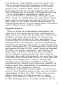
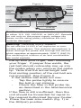
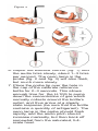
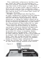
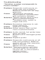
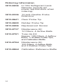
H-10G
Refrigerant
Leak Detector
Congratulations! You have just
purchased the most versatile,
high performance service leak
detector available in the industry today. It will detect refrigerants with a sensitivity that will
effectively pinpoint both small
and large leaks quickly and
efficiently. We encourage your
review of this manual to assure
satisfactory performance and a
long service life.
Condensed Instructions
1. Plug power cord into an appropriate AC
outlet and let unit warm up for 2 minutes.
2. Check flotation of airflow ball in probe tip.
3. Set Leak Size switch to SM(cal) position.
4. Adjust Balance Control until unit ticks
slowly (1–3 ticks per second).
5. Place probe tip over Calibrate Reference
Bottle (remove cap disc from bottle) and
check for faster audio and flashing lamp.
6. Probe for leaks.
7. For other sensitivity ranges, set Leak
Size switch and readjust Balance
Control for 1–3 ticks per second.
WARNING: This deviceis not to be
used in any application that is beyond
its intended purpose or beyond the
scope of its specifications. For details
on appropriate use, refer to the general model description, application, and
operation discussions in this manual.
Before risking equipment damage or
personal injury, contact Bacharach if you
are unsure of the validity of a particular
combustion analyzer application.
Model Description
The H-10G Halogen Leak Detector
consists of a control unit, a probe with
4-1/2 ft of hose, and an 8 ft power cord,
all housed in a shock-resistant case.
The control unit contains a printed circuit board amplifier, plug-in sensor, air
pump, power transformer, and speaker
housed beneath the chassis cover. A
calibrate reference leak bottle, leak size
switch, balance control, and power switch
are located on the top of the control
chassis. An AC power cord is attached
on the inside left of the control chassis. A
2
screwdriver adjustable sensor heat control is located on the bottom of the unit.
The probe nozzle consists of a transparent tip, airflow ball, filter, and neon
leak-signal lamp, connected to the control chassis by a length of flexible tubing.
The calibrated reference leak is a
removal bottle containing halogen gas
R11, and is calibrated to provide a leak
equivalent to approximately 0.5 ounce
per year of R134a. As an accessory, a
maintenance kit is provided that contains
extra filters and airflow balls.
Application
The H-10G is intended principally for
use as a serviceman’s tool, although it
also can be used for production line leak
testing. It was developed in response
to an industry that is in the process of
converting to more environmentally safe
refrigerants worldwide. Ozone depleting
chlorine is being reduced or eliminated in
most refrigerants. To adequately leak test
refrigerants like R123 and fluorine based
R134a, a higher detector sensitivity is
required. The H-10G has the capability to detect small leaks for all current
chlorine based refrigerants as well as the
new fluorine based R134a or new blends
under development. When using the
H-10G you can be confident it has the
sensitivity to meet your service needs of
today and the capability of meeting your
needs in the years to come.
Please note that heavy gas contamination in the testing area may cause erratic
operation of the H-10G. This can occur
when the leak in the system is very
large and there is little or no ventilation
in the testing area. Contamination of an
3
area may also occur where excessive
amounts of refrigerants are vented.
The H-10G cannot differentiate
between atmospheric contamination and
an actual leak because it will respond to
any halogen gas passing over the heated sensor. However, a large leak often
still can be located and the background
contamination discriminated against by
switching to the LG leak range.
A contaminated condition can be
improved greatly by ventilating or isolating the leak-check area.
Important: Avoid placing the probe directly
in a stream of concentrated halogen, as this
will drastically shorten the sensor life.
Operating Instructions
1. Before using the H-10G for the first
time, remove the paper disc from the
cap on the calibrate reference bottle
(fig. 1) and allow a few minutes for the
leak rate to stabilize. This disc is used
to avoid evaporation and should be
replaced after calibration. Be certain that
the bottle contains a quantity of halogen
R11. The liquid level can be observed
by pulling the bottle up from its spring
retainer clip and out of the panel. Initially
this bottle is filled with enough halogen
to last approximately 6 months.
2. Plug the power cord (fig. 1) into a
50/60 Hz AC outlet of the nominal voltage as listed on the unit’s rating plate.
3. The H-10G will start to warm up when
the power cord is plugged into an AC
outlet and the power switch is turned on.
Allow 2 minutes for warm-up.
4. Check for sufficient airflow by pointing
the probe tip toward the floor, covering
4
Figure 1
sensor
cover
power cord
calibrate
reference
bottle
flexible
hose
power
switch
leak size
switch
speaker
control unit chassis
balance control
probe tip
Caution: The H-10G is available for operation
on either 110, 120, 220/230, or 240V AC. Operate
the unit only on the proper supply voltage (as
shown on the rating plate); otherwise the unit
could be damaged.
Warning! Personal Injury Hazard
Do not use the H-10G in an explosive or combustible atmosphere. The ambient atmosphere is
drawn through the probe and through the sensor,
which operates at approximately 1000°F (540°C).
The resulting hot mixture of air and combustible
gas could explode.
the tip with your finger, then releasing
your finger. If proper flow exists, the
red ball should noticeably rise up into
the probe when you uncover the probe
tip. Note that the actual height and
final resting position of the red ball are
not important. See Figure 2.
If the airflow ball does not rise:
Tap the probe lightly to ensure
the ball is not sticking.
Check the filter in the probe tip,
as described in the Maintenance
section.
If the flow is still insufficient, then the
unit should be forwarded for repair to
the nearest Authorized Service Center.
5. Place the leak size switch (fig. 1) in
the SM(cal) position.
5
Figure 2
6. Adjust the balance control (fig. 1) until
the audio ticks slowly, about 1–3 ticks
per second. The neon lamp in the
probe (fig. 2 and fig. 3) will also flash,
but much more slowly.
7. Place the probe tip over the hole in
the cap of the calibrate reference
bottle for 2–3 seconds. This allows
enough time for the H-10G to pump
down the concentration of gas which
normally collects around the bottle’s
outlet, and thus arrive at a steady
state response (be sure that the bottle
contains a quantity of refrigerant). The
neon lamp in the probe should flash
rapidly, and the audio pitch should
increase markedly, but then back off
somewhat from the saturated, fullscale howl.
6
The calibrate reference bottle may
be used as often as necessary to
assure proper operation of determining the size of the leak. A leak that
causes an audio pitch about equal to
that produced by the calibrate reference has a leak rate of approximately
the same size, 0.5 ounce per year of
halogen R134a.
Proper unit response during the
R134a calibration reference test above
verifies proper sensitivity and operation for all three test positions: small,
medium, or large for either chlorine or
fluorine based refrigerants. Please refer
to the Product Sensitivity Levels chart
on the pocket of the inside lid, or see
this manual’s Specifications section.
The term R12 sensitivity is used to
represent chlorine based refrigerants
such as R12, R22, R123, etc. Use
the medium sensitivity switch position
to locate 0.5 oz/yr or greater leaks
of these type refrigerants. The term
R134a ratings apply to the most difficult
to detect, like fluorine based R134a or
SF6. Use the small sensitivity switch
position to locate 0.5 oz/yr or greater
leaks of these type refrigerants.
8. Hold the probe as close as possible
to the area being tested and move
Figure 3
neon lamp
airflow ball
filter
calibrate reference
bottle
7
the tip at about one inch per second
along seams or joints suspected of
leaking. When the probe encounters a leak, both the audio pitch and
the flashing rate of the neon lamp
will increase. Both will continue to
respond at the faster rate as long as
the probe is held at the leak.
9. For detecting much larger or smaller
leaks, set the leak size switch to the
appropriate range LG or MED, readjust
the balance control for slow ticking
(1–3 ticks per second), and probe
for leaks as in the previous step. The
calibrate reference cannot be used to
calibrate these two ranges. The factory,
however, can supply leak standards
of any value required for verification of
capability to specific leak rates.
Sensor Life Extension
The H-10G provides a sensor adjustment that substantially extends sensor
life. This procedure also provides for a
more accurately calibrated sensitivity
throughout the sensor life, and allows
compensation for abnormally high or low
line voltages (see Maintenance section).
The sensor heat control is a screwdriver adjustment accessible through a
hole on the bottom of the case. As the
H-10G is used and the sensor ages, its
sensitivity will gradually decrease.
The overall sensitivity and calibration of the H-10G may be restored by
gradually adjusting the sensor heat
control clockwise until finally, with a fully
aged sensor, the control knob will be
turned clockwise to indicate 2 o’clock
(fig. 4). After that, when the sensor
fails to respond properly, replace the
sensor following the procedure in the
Maintenance section and readjust the
sensor heat control back to 7 o’clock
8
(fig. 4) and perform calibration.
When making sensor adjustments,
move the sensor heat control in small
increments, either up or down, as appropriate. After each adjustment wait about
30 seconds for the sensor temperature
to stabilize, then check the sensitivity
as described in steps 5, 6, and 7, in the
Operating Instructions section.
Note: For best sensor life, avoid excessive sensitivity and excessive clockwise
setting.
Maintenance
The H-10G is designed for long life
with very little maintenance. A kit that
contains the necessary expendable
replacement parts is supplied with each
unit. Instructions for replacing these
items are described in the following sections.
Replacing the Filter
To protect the air pump from damage of foreign particles and moisture,
replace the filter (fig. 3) often. With
moderate use (15–30 minutes per day),
once a month should be sufficient.
To replace the filter, pick out the old
filter with a pin or tweezers. The fine
screen will remain in the tip. Insert the
new filter in the tip and make sure it is
firmly seated against the fine screen.
Figure 4
indicates sensor
adjustment range
12
7
2
3
9
6
sensor heat adjustment
9
Replacing the Sensor
The sensor is a plug-in unit that can
be discarded when expended. It needs
replacing when the H-10G no longer
responds to the calibrate reference
bottle, even with the sensor heat control
fully clockwise. Make sure that the calibrate reference bottle contains fluid.
1. Unplug the AC power cord and open
the sensor cover (fig. 1). The sensor
is now visible.
2. Allow the sensor to cool before touching it (approximately 15 minutes).
WARNING! Personal Injury Hazard
Sensor surface temperature may reach
390°F (200°C) during operation, and may
cause a burn if not allowed to cool.
3. Unplug and discard the sensor.
4. Insert a new sensor and close the
cover.
5. Set the sensor heat control (fig. 4) to
its 7 o’clock position.
6. Place the unit in operation and
check its sensitivity by following the
procedure in steps 5, 6, and 7 in
the Operating Instructions section.
Gradually adjust the sensor heat control more clockwise until the proper
response is obtained. Each time the
sensor heat control is adjusted, make
only small adjustments either up
or down as appropriate. After each
adjustment: wait about 30 seconds
for the sensor temperature to stabilize; adjust balance knob to 1–3 ticks;
and then re-check the sensitivity.
10
Troubleshooting
**Solution number corresponds to
Cause number**
Problem Responds continuously on
small leak size positions.
Balance control will not stop
response.
Cause 1Excessive sensitivity
2Atmosphere contaminated
with excessive halogen
Solution 1Reset sensor heat control
more counterclockwise.
2Ventilate area, switch to
larger leak size.
Problem Excessive response to calibrate reference
Cause High line voltage
Solution Reset sensor heat control
more counterclockwise
Problem Audio normal, but probe lamp
does not flash
Cause Burned out or damaged probe
lamp
Solution Replace probe
Problem Responds continuously on all
leak size positions. Balance
control will not stop response.
Cause 1Dirt in sensor
2Short circuit in sensor
Solution 1Remove sensor and blow
out with clean air (5 psi) to
remove dirt. If unsuccessful,
replace sensor.
2Replace sensor
11
Troubleshooting (continued)
**Solution number corresponds to Cause
number**
Problem No response to calibrate reference
Cause 1Calibrate reference empty
2No air flow. Probe ball does
not float
3Sensor exposed to excessive
amounts of halogen
4Water in probe
5Low line voltage
Solution 1Replace with part#3015-0864
2Replace filter in probe tip.
Check operation of pump.
3Place probe to clean air
and allow unit to run several
minutes while sensor purges
itself.
4While unit is operating, blow
clean air (5 psi) into the probe
tip for approximately 1 minute.
5Reset sensor heat control
more clockwise.
12
Specifications
Product Sensitivity (moving probe)
(Movement not to exceed 2 in/sec, not
greater than 0.25 inches from leak.)
Switch
Position
LG
MD
SM
R134a
R12
5.0
3.0
1.0
0.5
0.5
0.1
Product Sensitivity (stationary probe)
(Probe directly on leak source, no
movement.)
Switch
Position
LG
MD
SM
R134a
R12
5.0
3.0
0.5
0.1
0.1
.05
Power Supply
±10% (100, 120, 220,
240 volts) 50/60 Hz
20 watts, in accordance with rating plate
Response Time Approx. 1 second
Reference Leak Approx. 0.5 oz/yr R134a.
Approx. 6 months life,
refillable with R11.
Warm-up Time
Approx. 2 minutes
Temperature
Operating 0°C to 45°C
(32°F to 113°F)
Storage
60°C (140°F) max.
Dimensions
8.7 x 5.5 x 1.4 inches
(22 x 14 x 7.5 cm)
Weight
3.2 pounds
(1.4kg)
13
Ordering Informaion
3015-0456 H-10G Refrigerant Leak
Detector (specify AC
power requirements when
ordering)
3015-0326 14 inch Flexible Probe
Extension
3015-0641 Clear Probe Tip
3015-0680 Rubber Probe Tip
3015-0486 Replacement Sensor
3015-0737 Maintenance Kit:
12 Filters, 4 Airflow Balls
3015-0781 Tune-Up Kit:
Sensor, 100 Filters, 4 Airflow
Balls, 3 Rubber Probe Tips,
and Calibration Bottle
3015-0784 Maintenance Kit:
100 Filters, 4 Airflow Balls,
and 3 Rubber Probe Tips
3015-0864 Calibration Reference Bottle
14
Repair Information
Should it become necessary to
repair your H-10G, please contact an
Authorized Service Center. Units should
be carefully packed to prevent shipping
damage and shipped prepaid.
Warranty
Send units under warranty and a copy
of the purchase receipt to an Authorized
Service Center for repairs. Please
include your company name, telephone
number including area code, and a contact name.
Non-Warranty
Units that are no longer under warranty
will be repaired to factory specifications
for a nominal fee. Please include your
company name, telephone number including area code, and a contact name.
Limited Warranty
The purchaser is warranted that this leak
detector will be free of defects in material
and workmanship for 3 years from date of
purchase. This warranty does not cover
sensors, reference leaks, filters, airflow
balls, lamps, or probe tips. Damages
caused by the user will not be covered. If
any defects are discovered during the warranty period, an Authorized Service Center
will repair or replace the unit at their option.
The foregoing limited warranty is exclusive
and in lieu of all other warranties, whether
written or implied, and no warranty of merchantability or fitness for purpose will apply.
15
Authorized Service Centers
United States
Bacharach Sales/Service Center
621 Hunt Valley Circle
New Kensington, PA 15068
Phone: 724-334-5051
Fax: 724-334-5723
E-mail: [email protected]
Canada
Bacharach of Canada, Inc.
20 Amber St. Unit #7
Markham, Ontario L3R 5P4
Canada
Phone: 905-470-8985
Fax: 905-470-8963
E-mail: [email protected]
16
Notes:
17
Notes:
18
Notes:
19
621 Hunt Valley Circle
New Kensington, PA 15068
Ph: 724-334-5000 • Fax: 724-334-5001 • Toll Free: 1-800-736-4666
Website: http://www.MyBacharach.com • E-mail: [email protected]
3015-0846
REV. 8 - 9/2012