1
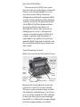
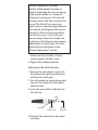
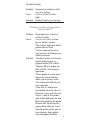
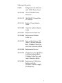
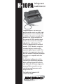
H-10PA
Refrigerant
LeakDetector
Congratulations! You have just
purchased the most versatile, high
performance service leak detector
available in the industry today. This
product has all the capability of
the proven H10PM model except
it does not contain the rechargeable battery and charger. The
H10PA is powered by an external
mobile 12 VDC battery using the
included battery clamp and/or
cigarette lighter power cable. This
provides for ongoing testing without the need for frequent overnight
recharge as is required with the
H10PM.
It will detect refrigerants with a
sensitivity to effectively pinpoint
both small and large leaks quickly
and efficiently. We encourage your
review of this manual to assure
satisfactory performance and a
long service life.
For technical support call:
1-800-736-4666
How the H10PA Works
The sensor in the H10PA uses a positive ion emission technology, commonly
known as the heated diode. It is very
sensitive to only halon substances
(refrigerants) making this product highly
resistive to false alarming, while retaining
superior sensitivity for pinpointing the
most difficult to find refrigerant leaks.
A pump inside the unit draws air
through the sensor. Any presence of
halogen gases (such as refrigerants)
causes an ionized current to flow that
sounds a speaker and illuminates a
neon light in the probe. Sensitivity to
pinpoint both large and small leaks can
be controlled by adjusting a three-position switch.
Panel Operating Controls
Before you use the unit for the first time:
Sensor Heat
Adjustment
(turn clockwise
to increase heat)
Power
Plug
Sensor
Power
Switch
Calibration
Reference
Bottle
Mode
Switch
Sensitivity Switch
Sensor “Set”
Indicators
Remove the sticky-label disc from the
cap of the CALIBRATION REFERENCE bottle.
This disc can be reused to help seal the
vial when the leak detector is not in use
or it can be discarded. DO NOT attempt
to unscrew the cap; you may damage
the bottle! It is filled with enough refrigerant to last approximately six months.
2
Operating Instructions
1. Using the included cables, connect
to the 12VDC Battery and plug cable
into the unit.
2. Slide LEAK SIZE switch to its SM (small)
position.
3. Slide POWER switch to its ON position.
4. Check for sufficient airflow by pointing the probe tip toward the floor and
observing the red airflow ball in the
probe tip. It should be floating inside
the probe tip.
5. Allow two minutes for the sensor to
warm up; the flashing probe light and
sound indicator will idle at 2–3 clicks
per second.
6. Test operation by quickly touching
the top of the CALIBRATION REFERENCE bottle (make sure sticky label is
removed). The unit should respond
with a rapid flash rate and sound verifying correct operation and optimum
sensitivity for detecting all refrigerant
leaks. During product life, if unit does
not respond correctly, see Section
Sensor Heater Adjustment.
Setting the Sensitivity
Small (SM) switch position is the
highest sensitivity. The unit will indicate 0.1 ounce or greater leak rates
and is used for fluorine based gases
like R134a and SF6. This position also
assures highest repeatability for locating
0.5 ounce or greater R134a leaks (per
SAE Std. J1627 moving probe test
conditions). It must always be used to
verify performance and calibration when
using the CALIBRATION REFERENCE bottle.
3
Medium (MED) position sensitivity is
used for chlorine and chlorine based
gases like R12, R22, R123, etc. and will
indicate a 0.1 ounce per year or greater
leak rate. This position supports finding
a 0.5 ounce or greater leak during the
moving probe test as defined in SAE
J1627. It is also useful for locating larger
R134a leaks of one ounce or greater.
Large (LARGE) position is used to zero
in on gross leaks of any refrigerant. If
a large leak is suspected, set mode
switch to MANUAL. Adjust BALANCE knob
for a sound of 2–3 ticks per second
and slowly approach the test equipment/area. Continue to turn the BALANCE
knob counterclockwise as necessary to
maintain 2–3 ticks per second. As you
approach the vehicle or equipment, the
gas concentration will increase, causing
an alarm condition. Each time an alarm
occurs, re-adjust the BALANCE control.
Continue this process until the leak is
located. Blowing out the test site with
shop air may enable you to locate the
leak more quickly.
Note: After a large leak is located and
repaired, blow out the area again with
shop air, set the unit on the small leak
sensitivity and double check equipment
for small leaks.
Warning! Personal Injury Hazard.
Do not use the H10PA in an explosive or combustible atmosphere. The
ambient atmosphere is drawn through
the probe and through the sensor,
which operates at approximately
1472°F (800°C). The resulting hot
mixture of air and combustible gas
could explode.
4
NOW…
YOU’RE READY TO FIND THE LEAK!
(You have a choice of two modes)
Auto Mode
This mode is preferred because the
unit effectively auto zeros to block out
background levels of refrigerants and
changes in background contamination.
This greatly reduces and/or eliminates
false alarms while retaining sensitivity
to quickly locate small or medium size
leaks. Pinpointing leaks in this mode
requires continuous probe movement.
(We recommend 2 inches per second
as specified in SAE J1627 and J1628).
If the probe remains on the leak the
unit will zero out the leak, going into
the idle 2–3 ticks/second condition.
Briefly moving the probe away from the
leak for 1–2 seconds permits the fast
auto recovery to re-establish sensitivity.
Returning to the leak site, the unit will
alarm again. The unit will reliably and
repeatedly pinpoint the leak with each
pass over the leak site.
If a large gross leak is present, the
auto zero circuit may reduce sensitivity
to an unacceptable level to find small
and medium sized leaks. If this condition
exists, the manual mode will enable you
to pinpoint the large leak. The manual
mode is also an effective means to
determine if a gross leak of any refrigerant exists prior to searching for leaks
(see Section Setting the Sensitivity).
Manual Mode
In the Manual Mode the auto zero
function is disabled, causing the unit
not to zero out the leak if the probe is
5
held at the leak site. This mode may
require frequent re-adjustment of the
BALANCE control to maintain the required
2–3 ticks per second that indicates
proper adjustment and calibration for
all three sensitivity switch positions. In
this mode you may notice sensitivity
is slightly greater (10–20%) than the
100% auto zero mode. This is normal.
Sensor Heater Adjustment
The sensor’s HEATER ADJUSTMENT controls the sensitivity of the unit. A heat
setting that is too high causes instability
due to excessive sensitivity and shortens sensor life. The Low, OK, and High
LED indicators in conjunction with the
HEATER ADJUSTMENT and the CALIBRATION
REFERENCE bottle, is a unique system
for setting the correct sensor heat (sensitivity) for optimum calibrated performance and long sensor life.
The unit is preset for optimum initial
operation. To check the setting, slide
the LEAK SIZE switch to its SM (small)
position, turn ON the unit and allow it
to stabilize (approximately 2 minutes).
When stabilized, at 2–3 clicks per second, briefly touch the CALIBRATION REFERENCE bottle with the probe (after removing the sticky label disc from the top of
the bottle). If adjusted properly, the red
Low LED light will go out and the green
OK LED will briefly light. This indicates
the sensor heat/sensitivity is adjusted
for optimum performance.
If the red LED Low light remains on
when you briefly touch the bottle, the
HEATER ADJUSTMENT is set too low and
must be turned slightly clockwise; afterwhich, allow the unit to stabilize about
6
one minute and retest. If necessary,
continue to rotate the HEATER ADJUSTMENT
clockwise and retest until the green OK
LED briefly comes on. If during this test
the red High LED comes on, the heat is
set too high and the HEATER ADJUSTMENT
should be turned slightly counterclockwise. Allow the unit to stabilize and then
repeat the test. Continue this procedure
until proper green OK LED operation
has been achieved.
NOTES:
A. After initial check for correct adjustment, disregard Low, OK, High LED
indication. Their indication is meaningless during subsequent leak testing
activity.
B. Check for proper heat adjustment
the first time the unit is turned on and
repeat on a daily basis. This assures the
product is calibrated for the correct sensitivity in all leak size switch positions
for your daily test activity.
C. Frequency of sensor heat adjustment
is a function of how much exposure the
sensor has to refrigerant. Adjustment
may be required every 2 weeks for
heavy duty service and once every few
months for light duty service. The sensor LED status indicators will accurately
tell you when adjustment is necessary
during the daily check.
D. It is time to replace the sensor when
the HEATER ADJUSTMENT is fully clockwise
and the green OK LED will not come
on. Before replacing the sensor, turn the
HEATER ADJUSTMENT fully counterclockwise; plug in a new sensor; then test
and adjust as previously described to
correctly calibrate the instrument.
7
Application Notes
1. Conduct a leak check in a logical progression through the entire system to
locate all leaks. If surfaces are particularly dirty, or wet, wipe them off with a
clean, dry cloth to reduce filter clogging and extend sensor life. DO NOT
allow the unit to ingest moisture. Use
of the supplied rubber probe tip helps
prevent moisture from being drawn
into the unit. Check ports for moisture
before inserting the probe.
2. After locating and repairing any leaks
requiring the use of the LARGE setting,
switch to the MEDIUM setting and verify
the system is free of leaks. For HFC
refrigerants only (such as R134a), you
also must verify the system is leak free
using the SMALL setting. For CFC and
HCFC systems (such as R11, R12,
R22, R123), the MEDIUM setting is
sufficient to verify that the system is
free of leaks that require repairing.
Maintenance
To protect the air pump from damage
due to foreign particles and moisture,
replace the filter as it becomes dirty. With
moderate use (15 to 30 minutes a day),
it is recommended that the filter be
replaced once a month. In dirty environments or with heavy use, replace the
filter more often. Always replace the filter
when it is visibly dirty or wet.
Replacing the Filter:
1. Remove the black rubber probe tip.
2. Pick out the filter with a pin or tweezers.
A fine screen will remain in the tip of
the probe.
3. Insert the new filter in the probe tip.
8
Caution: Equipment Damage
Hazard. Submerging the probe in
liquid will damage the vacuum pump.
Exposing the probe to a stream of
refrigerant coming out of a tank will
severely reduce the life or destroy the
sensor. The life of this unique rare
earth sensor is directly proportional to
the amount of refrigerant that passes
through it. With normal intermittent
service, the sensor can last for one
year or longer. Exposure to high concentrations of refrigerant may require
adjustment of sensor heat. To check,
repeat the test procedure in the
“Heater Adjustment” section.
Make sure that the filter is firmly
seated against the fine screen.
4. Replace the rubber probe tip.
Replacing Airflow Ball Indicator:
1. Remove the clear plastic section of
the probe tip by gently pulling and
twisting the white grip.
2. Turn the probe tip upside-down and
tap on it to remove the old airflow
indicator ball.
3. Insert the new airflow indicator bal
into the tip.
Filter
Probe Tip
Airflow
Indicator Ball
Rubber
Probe Tip
4. Reattach the probe tip to the probe
assembly.
9
Replacing the Sensor:
The sensor is a disposble plug-in unit.
Replace it when the H10PA no longer
responds to the CALIBRATION REFERENCE
bottle, even with the sensor HEATER
ADJUSTMENT turned fully clockwise
(make sure the CALIBRATION REFERENCE
bottle contains some refrigerant).
1. Set the POWER switch to OFF.
2. Unplug the power cord if the unit
is plugged in and open the sensor
cover.
3. Allow the sensor to cool before handling.
Warning! Personal Injury Hazard.
Sensor surface temperature may reach
390°F (200°C) during operation, and may
cause a burn if not allowed to cool.
4. Unplug and discard the sensor.
5. Insert a new sensor and close the
sensor cover.
6. Turn the sensor HEATER ADJUSTMENT to
its full counterclockwise position.
7. Apply power to the unit and reset
the HEATER ADJUSTMENT (see Section
Sensor Heater Adjustment).
10
Troubleshooting
Problem
Cause
Solution
Responds to reference leak
on LARGE setting.
HEATER ADJUSTMENT set too
high.
Readjust heater (see section
Sensor Heater Adjustment).
**Solution number corresponds to
Cause number**
Problem
Cause
Solution
No response to CALIBRATION
REFERENCE bottle.
1HEATER ADJUSTMENT set too
low or bottle is empty.
2No air flow (indicator ball in
probe doesn’t float).
3Sensor exposed to excessive amounts of halogen gas.
4Water in probe.
1Readjust heater (see Sensor
Heater Adjustment) or
replace bottle (3015-0864).
2Replace filter in probe tip
(3015-0784). Check pump
operation.
3Move probe to clean atmosphere for several minutes
while sensor purges itself.
Test reference bottle for correct operation.
4Turn unit OFF and disconnect probe from the chassis.
Remove screws and take out
chassis. Look at the underside of the leak detector and
follow the probe to the pump.
Remove this hose from the
pump. Blow clean air (5 psi)
into the probe tip for one or
two minutes. Reassemble
unit and replace the filter
11
(3015-0864).
Troubleshooting (continued)
Problem
Cause
Solution
Problem
Cause
Solution
12
Erratic response in all leak
positions.
1Filter is clogged.
2Dirt in sensor.
3Short circuit in sensor.
4Atmosphere contaminated
with excessive refrigerant
gas.
1Replace filter (3015-0784).
2Remove sensor and blow it
out with clean air (not over
10 psi). If unsuccessful,
replace sensor (3015-0486).
Replace filter (3015-0784).
3Replace sensor (3015-0486).
4Ventilate Area.
Responds continuously only
in small leak position.
Excessive sensitivity.
Readjust heater (see Sensor
Heater Adjustment).
Ordering Information
H10PA
Refrigerant Leak Detector
with 12VDC Power Cord
3015-0326 14 inch Flexible Probe
Extension
3015-0119 100-240VAC Charge/Run
AC Adapter
3015-4161 Battery Clamp Adapter
Cable
3015-0868 Cigarette Lighter Adapter
Cable
3015-0641 Replacement Probe Tip
3015-0680 Replacement Rubber
Probe Tip
3015-0781 Tune-up kit; (Sensor, 100
Filters, 3 Airflow Indicator
Balls, 3 Rubber Probe Tips,
and Leak Calibration Bottle
3015-0486 Replacement Sensor
3015-0784 Maintenance kit; (100 filters,
3 Airflow Indicator Balls,
3 Rubber Probe Tips, and
Leak Calibration Bottle
3015-0864 Replacement Calibration
Reference Bottle
(contains 6 month supply
of refrigerant)
13
Repair Information
Should it become necessary to repair
your H-10PA, please contact an authorized service center. Units should be
carefully packed to prevent shipping damage and shipped prepaid.
Warranty
Send units under warranty and a copy
of the purchase receipt to an authorized
service center for repairs. Repairs will
be completed and the unit(s) returned
to you with the same priority of shipment that it was received. Please include
your company name, telephone number
including area code, and a contact name.
Non-Warranty
Units that are no longer under warranty
will be repaired to factory specifications for a nominal fee. The unit will be
returned to you with the same priority
of shipment that it was received. Please
include your company name, telephone
number including area code, and a contact name.
Limited Warranty
The purchaser is warranted that this leak
detector will be free of defects in material and workmanship for 5 years from
date of purchase. This warranty does not
cover sensors, reference leaks, filters, airflow balls, lamps, or probe tips. Damages
caused by the user will not be covered. If
any defects are discovered during the warranty period, an authorized service center
will repair or replace the unit at their option.
The foregoing limited warranty is exclusive and in lieu of all
other warranties, whether written or implied, and no warranty of merchantability or fitness for purpose will apply.
14
Authorized Service Centers
United States
Bacharach, Inc.
621 Hunt Valley Circle
New Kensington, PA 15068
Phone: 724-334-5000
Fax: 724-334-5001
E-mail: [email protected]
Canada
Bacharach of Canada, Inc.
20 Amber St. Unit #7
Markham, Ontario L3R SP4
Canada
Phone: 905-470-8985
Fax: 905-470-8963
E-mail: [email protected]
15
SAE J1627
621 Hunt Valley Cirlce
New Kensington, PA 15068
WEBSITE: http://www.mybacharach.com
PH: 724-334-5000 FAX: 724-334-5001
3015-0952
REV. 3 – 11/2009