1
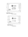
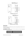
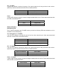
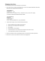
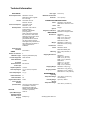
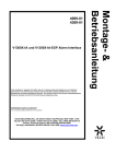
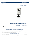
XX164-10
MODEL VF-404 SERIES
FOUR-CHANNEL FIBER-OPTIC VIDEO
TRANSMISSION SYSTEM
Copyright © 2007 Vicon Industries Inc. All rights reserved.
Product specifications subject to change without notice.
Vicon and its logo are registered trademarks of Vicon Industries Inc.
VICON INDUSTRIES INC., 89 ARKAY DRIVE, HAUPPAUGE, NEW YORK 11788
TEL: 631-952-CCTV (2288) FAX: 631-951-CCTV (2288) TOLL FREE: 800-645-9116
24-Hour Technical Support: 800-34-VICON (800-348-4266)
UK: 44/(0) 1489-566300 WEB: www.vicon-cctv.com
Vicon part number 8009-8164-10-00
Rev 607 Section 11
FCC Notice
Note: Complies with Federal Communications Commission Rules & Regulations Part 15, Subpart B for a
Class A digital device.
WARNING
This equipment generates and uses radio frequency energy and if not installed and used
properly, that is, in strict accordance with the manufacturer’s instruction, may cause interference
to radio and television reception. It has been type tested and found to comply with the limits for
a Class A computing device in accordance with the specification in subpart B of part 15 of the
FCC rules, which are designed to provide reasonable protection against such interference in a
commercial installation. However, there is no guarantee that interference will not occur in a
particular installation. If this equipment does cause interference to radio and television
reception, which can be determined by turning equipment off and on, the user is encouraged to
try and correct the interference by one or more of the following measures:
•
Reorient the receiving antenna.
•
Relocate the equipment with respect to the receiver.
•
Relocate the equipment away from the receiver.
•
Plug the equipment into a different electrical outlet so that the equipment and
receiver are on different branch circuits.
If necessary, the user should consult the dealer or an experienced radio/television technician for
additional suggestions.
The user may find the following booklet prepared by the Federal Communications Commission
helpful:
“Interference Handbook, Bulletin CIB-2”
This booklet is available from the U.S. Government Printing Office, Superintendent of
Documents, Mailstop SSOP, Washington, D.C. 20402-9328, ISBN 0-16-045542-1.
Warning: Power must be removed from this unit before removing circuit modules or ribbon cables.
Caution: This unit contains circuit cards with integrated circuit devices that can be damaged by static
discharge. Take all necessary precautions to prevent static discharge
Important Safeguards
GRAPHIC SYMBOL EXPLANATION
The lightening bolt symbol alerts the user to the presence of
dangerous voltage that may present the risk of electric
shock.
1984, provides information on proper grounding of the leadin wire to an antenna discharge unit, size of grounding
conductors and the requirements of grounding electrodes.
14. Lightning - Disconnect the product from its power
source and cable system when possible to prevent damage
due to lightning and power-line surges.
15. Power Lines - Do not locate outside cables over power
or utility lines where they can fall and make direct contact.
Contact with power lines can be fatal.
16. Overloading - Do not overload wall outlets and
extension cords to prevent risk of fire and electric shock.
17. Object and Liquid Entry - Never probe through, or spill
liquid into, enclosure openings to prevent risk of fire or
electric shock.
18. Servicing - Refer all servicing to qualified service
personnel.
The exclamation point symbol alerts the user to the presence
19. Damage Requiring Service - Obtain service when:
of important operating and maintenance instructions.
1. Read Instructions - Read all safety and operating
a)
The power-supply cord or plug is damaged.
b)
Objects have fallen or liquid has been spilled into the
product.
c)
The product is not designed for outdoor use and has
been exposed to water or moisture.
d)
The product does not operate per the operating
instructions. Perform Vicon recommended adjustments,
modifications and troubleshooting only to avoid unit
damage and personal injury.
e)
The product has been dropped.
f)
The product
performance.
instructions before the product is operated.
2. Retain Instructions - Retain all safety and operating
instructions for future reference.
3. Heed Warnings - Pay attention to all product warnings.
4. Follow Instructions - Follow all operating instructions.
5. Cleaning -(Do not use caustic, abrasive or aerosol
cleaners)
a)
b)
For units that CAN BE DISCONNECTED from the
power source, use a damp cloth for cleaning.
For units that CANNOT BE DISCONNECTED from the
power source, use a damp cloth for cleaning and do not
allow moisture or liquids to enter vents.
6. Attachments - Use only UL Listed Vicon recommended
attachments to prevent unit damage and personal injury.
7. Water and Moisture - Use only products designed for
outdoor environments where they will be exposed to water or
moisture.
8. Accessories - Do not place the unit on an unstable
surface to avoid falling. Use only UL Listed Vicon recommended
mounting accessories.
9. Ventilation - Do not block ventilating slots and openings
as they ensure reliable operation. Do not place the unit near
a heat source or into an enclosure unless recommended by
Vicon.
2 indoor/dry or Class 3 outdoor/wet power supply.
11. Grounding - Only products equipped with a 3-prong
grounded plug should be inserted into a grounded power
outlet. Contact an electrician to replace an obsolete outlet.
Do not force a plug into a non-grounded outlet.
12. Power Cord Protection - Power supply cords should not
be routed in trafficked areas or in tight spaces where they
will be pinched or used to bear weight. Allow some slack in
the cord where it enters the unit.
13. Outdoor Cable Grounding - Use only grounded outdoor
cables to protect against voltage surges and static charges.
Section 810 of the National Electrical Code, ANSI/NFPA 70-
a
significant
change
in
20. Replacement Parts - Use only Vicon specified
replacement parts or an approved equivalent to prevent unit
damage and injury.
21. Safety Check - Request safety checks to be performed
following repair or maintenance to verify proper operation.
22. ESD Precaution - Take all normal electrostatic
discharge precautions to avoid component damage during
installation and operation.
23. For 230 VAC Devices Only - When the disconnect
device is not incorporated in the equipment or when the plug
on the power supply is intended to serve as the disconnect
device, follow the guidelines below:
a)
For permanently connected 230 VAC units, a readily
accessible disconnect device must be incorporated into
10. Power Sources - The product should only be operated
from the recommended power source. Use only a UL Class
shows
the site wiring.
b)
For 230 VAC units with a plug, the outlet must be
installed near the unit and be easily accessible.
Introduction
The information in this manual covers the installation of the VF-404 Fiber-Optic Video Transmission
System. This system should only be installed by a qualified technician using approved materials and
wiring practices in accordance with the National Electrical Code ANSI/NFPA 70, state, and local electrical
codes. Read these instructions thoroughly before beginning an installation.
Functional Description
The VF-404 system operates as a transmitter/receiver pair for the transmission of four simultaneous, realtime, baseband NTSC, PAL, RS170, or RS343 video signals. The standalone transmitter is Model VF404T; the rack-mount version is VF-404TR. The standalone receiver is model VF-404R; the rack-mount
version is model VF-404RR. The transmitter operates with the receiver over one multimode fiber optic
cable.
The transmitter accepts up to four video inputs. Each video input modulates a separate FM carrier
frequency to allow the total of four video signals to be combined onto one fiber. The VF-404 Series is
designed to operate over an optical loss budget range of 0 to 6 dB and a maximum distance of 2.5 km
when used on 62.5 um multimode fiber. The system will also operate on 50 um multimode fiber at a
reduced loss budget range.
The standalone modular units are contained in a compact and rugged extruded aluminum housing with
internal DC voltage regulation. The detachable terminal block and LED indicators provide for easy
installation and monitoring of video and power supply. The rack-mount units are designed for rack
mounting in the VF-SR-20/2 card cage. Slide in rack mounting and a LED indicator provide for easy
installation and monitoring of video and power.
Installation
Standalone Modules
Mount the unit to a secure surface using #8 (3mm) hardware in four places. See the drawing on the next
page for mounting dimensions. Be sure to allow sufficient room for the required minimum bend radius of
the fiber cable used.
Rack-Mount Cards
The unit slides into any open slot in the VF-SR-20/2 card cage. Use a small screwdriver to push and lock
the two ¼-turn fasteners into place. Please note that when installing this card in the position directly next
to the power supply in the card cage, it may be necessary to make the signal connections at the rear of
the card before fully seating the card into its slot.
Power Source
Note: This product (standalone unit) should be powered by a listed Class 2 power supply only.
For the standalone units, power to the unit must be within the specifications listed. A 24 VAC center tap
transformer rated at 400 mA is required. For the standalone units, an appropriate power supply is
included with the unit.
For the rack-mount models, power is supplied by the card cage. Please refer to the VF-SR-20/2 and VFPSR-2 instruction manual XX164-60 for further details.
Power Connection
On standalone units, power is supplied to the unit via a three-pin Phoenix connector. The ground wire
from the center tap supply must be connected to the center pin of the Phoenix connector. When installed
properly, the nominal voltage measured from the center pin to either of the outside pins will be 12 volts
AC and the nominal voltage measured from one outside pin to the other outside pin will be 24 volts AC.
For rack-mount units, power is supplied to the unit via a four finger backplane connector. The VF-404TR
and VF-404RR can be inserted into the card cage or removed from the card cage with power applied to
the backplane.
Input/Output Connections
The fiber optic connection is made via a ST connector located on the left side of the standalone units and
the back of the rack-mount units.
Video input connections are located on the right side of the standalone units and the back of the rackmount units. A BNC connector is provided for each channel. The video inputs are connected to an
appropriate 75Ω baseband video source such as a camera or a video recorder output. For optimum
performance, the video cables should be the shortest length of coax practical.
VF-404T Transmitter
VF-404R Receiver
VF-404RR Rack-Mount Receiver
VF-404TR Rack-Mount Transmitter
Status Indicators
Standalone Units
The VF-404T transmitter and VF-404R receiver provide the following LED status indicators to aid in
installation and troubleshooting:
VLI 1 through VLI 4 – VF-404T
A green LED indicator is provided for each of the four video channel inputs. Video status associated with
each of these LEDs is summarized below.
Video Level Indicator
Video Status
Green
Proper Input Video Present
Off
Input Video not Detected
XX164-10 VF-404 Transmission System
Status Indicators • 5
OLI – VF-404R
A green LED indicator monitors the power of the optical signal that is being received at the receiver.
Optical input status associated with this LED is summarized below.
Optical Level Indicator
Optical Status
Green
Proper Optical Input Power Present
Off
Optical Input not Detected
Power
A green LED indicator monitors the internal voltages created within the unit. Power status associated with
this LED is summarized below.
Power Indicator
Power Status
Green
Voltage Present
Off
Voltage not Present
Status Indicators
Rack-Mount Units
The VF-404TR transmitter and VF-404RR receiver provide the following LED status indicators to aid in
installation and troubleshooting:
VLI 1 through VLI 4 – VF-404TR
A bi-color LED indicator is provided for each of the four video channel inputs. Video status associated
with each of these LEDs is summarized below.
Video Level Indicator
Video Status
Green
Proper Input Video Present
Red
Input Video Not Detected
Off
Check Power Supply
OLI – VF-404RR
A bi-color LED indicator monitors the power of the optical signal that is being received at the receiver.
Optical input status associated with this LED is summarized below.
Optical Level Indicator
Optical Status
Green
Proper Optical Input Power Present
Red
Optical Input Not Detected
Power – VF-404R
A green LED indicator monitors the internal voltages created within the receiver. Power status associated
with this LED is summarized below.
Power Indicator
Power Status
Green
Voltage Present
Off
Check Power Supply
Shipping Instructions
Use the following procedure when returning a unit to the factory:
1. Call or write Vicon for a Return Authorization (R.A.) at one of the locations listed below. Record the
name of the Vicon employee who issued the R.A.
Vicon Industries Inc.
89 Arkay Drive
Hauppauge, NY 11788
Phone: 631-952-CCTV (2288); Toll-Free: 1-800-645-9116; Fax: 631-951-CCTV (2288)
For service or returns from countries in Europe, contact:
Vicon Industries Ltd
Brunel Way
Fareham, PO15 5TX
United Kingdom
Phone: +44 (0) 1489 566300; Fax: +44 (0) 1489 566322
2.
Attach a sheet of paper to the unit with the following information:
a.
Name and address of the company returning the unit
b.
Name of the Vicon employee who issued the R.A.
c.
R. A. number
d.
Brief description of the installation
e.
Complete description of the problem and circumstances under which it occurs
f.
Unit’s original date of purchase, if still under warranty
3. Pack the unit carefully. Use the original shipping carton or its equivalent for maximum protection.
4. Mark the R.A. number on the outside of the carton on the shipping label.
Technical Information
ELECTRICAL
Power Requirements:
Current:
Power Consumption:
Heat Equivalent:
Radio Emission
Standard:
Fiber Type:
Standalone: 24 VAC.
Rack Mount: power supplied
from card cage.
Transmitter: 375 mA.
Receiver: 330 mA.
Transmitter: 5.6 W.
Receiver: 5.0 W.
Transmitter: 0.321 btu/min
(0.08 kg-cal/min).
Receiver: 0.282 btu/min
(0.07 kg-cal/min).
Note: These figures represent
the conversion of 100% of the
electrical energy to heat. Actual
percentage of the heat
generated will be less and will
vary from product to product.
These figures are provided as an
aid in determining the extent of
cooling required for an
installation.
FCC Class A.
VIDEO
Number of Channels:
Modulation Type:
Formats Supported:
4.
Frequency Modulation (FM).
10 MHz.
Horizontal
Video Resolution:
800 TV lines.
Video Input Signal:
Video Output Signal:
Differential Phase:
Differential Gain:
Signal-to-Noise Ratio:
Interconnection
Distance
(recommended):
OPTICAL
Optical Wavelength:
Maximum Optical
Attenuation (Loss
Budget):
50 or 62.5 μ.
1.6 mi (2.5 km).
CONNECTORS AND INDICATORS
Power:
Video:
Optical:
Diagnostics Indicators:
MECHANICAL
Dimensions:
Weight:
Construction:
Standalone: 3-pin Phoenix.
Rack Mount: connector in rack.
BNC.
ST type.
Video, power and optical
presence bi-color/green LEDs.
Standalone
Height: 1.1 in. (28 mm).
Width: 5.5 in. (139.7 mm).
Depth: 8.9 in. (226 mm).
Rack Mount: 2 slots.
Standalone: 1.5 lb (0.7 kg).
Rack Mount: 0.8 lb (0.4 kg).
Aluminum.
Finish:
Standalone: Silver.
Rack Mount: Black paint.
Mounting:
No. 8 (3 mm) hardware, 4
places.
Shipping Dimensions:
Standalone
Height: 3.5 in. (89 mm).
Width: 8.3 in. (211 mm).
Depth: 14.5 in. (368 mm).
Rack Mount
Height: 3.1 in. (77 mm).
Width: 7 in. (178 mm).
Depth: 10.2 in. (259 mm).
NTSC and PAL
Video Bandwidth:
Video Input/
Output Impedance:
Maximum Transmission
Distance*:
75 ohms.
Shipping Weight:
1 V p-p nominal, composite
video.
Standalone: 3 lb (1.4 kg).
Rack Mount: 1.2 lb (0.5 kg).
Shipping Volume:
Standalone: 0.2 ft (0.006 m ).
3
3
Rack Mount: 0.13 ft (0.004 m ).
1 V p-p.
3°.
5%.
55 dB.
100 ft (30 m) (video equipment
to transmitter or receiver).
Recommended cable type:
RG59/U coaxial cable (Belden
no. 9259 or equivalent).
ENVIRONMENTAL
Operating
Temperature Range:
Humidity Range:
Storage
Temperature Range:
1300 nm.
6 dB (62.5 μ).
3
*Pending optical cable loss.
-40 to 165° F (-40 to 74° C),
noncondensing.
Up to 95%, relative.
-40 to 185° F (-40 to 85° C)
3
Vicon Standard Equipment Warranty
Vicon Industries Inc. (the “Company”) warrants your equipment to be free from defects in material and
workmanship under Normal Use from the date of original retail purchase for a period of three years, with the
following exceptions:
1.
2.
3.
4.
5.
VCRs, all models: Labor and video heads warranted for 120 days from date of original retail
purchase. All other parts warranted for one year from date of original retail purchase.
Video monitor CRT (cathode ray tube) and LCD monitors, all models: One year from date of original
retail purchase.
Uninterruptible Power Supplies: Two years from date of original retail purchase.
VDR-204 and VDR-208 Recorder Series: One year from date of original retail purchase.
Normal Use excludes prolonged use of lens and pan-and-tilt motors, gear heads, and gears due to
continuous use of “autopan” or “tour” modes of operation. Such continuous operation is outside the
scope of this warranty.
Date of retail purchase is the date original end-user takes possession of the equipment, or, at the sole
discretion of the Company, the date the equipment first becomes operational by the original end-user.
The sole remedy under this Warranty is that defective equipment be repaired or (at the Company’s option)
replaced, at Company repair centers, provided the equipment has been authorized for return by the
Company, and the return shipment is prepaid in accordance with policy.
The Company will not be obligated to repair or replace equipment showing abuse or damage, or to parts
which in the judgment of the Company are not defective, or any equipment which may have been tampered
with, altered, misused, or been subject to unauthorized repair.
Software supplied either separately or in hardware is furnished on an “As Is” basis. Vicon does not
warrant that such software shall be error (bug) free. Software support via telephone, if provided at
no cost, may be discontinued at any time without notice at Vicon’s sole discretion. Vicon reserves
the right to make changes to its software in any of its products at any time and without notice.
This Warranty is in lieu of all other conditions and warranties express or implied as to the Goods,
including any warranty of merchantability or fitness and the remedy specified in this Warranty is in
lieu of all other remedies available to the Purchaser.
No one is authorized to assume any liability on behalf of the Company, or impose any obligations on it in
connection with the sale of any Goods, other than that which is specified above. In no event will the
Company be liable for indirect, special, incidental, consequential, or other damages, whether arising from
interrupted equipment operation, loss of data, replacement of equipment or software, costs or repairs
undertaken by the Purchaser, or other causes.
This warranty applies to all sales made by the Company or its dealers and shall be governed by the laws of
New York State without regard to its conflict of laws principles. This Warranty shall be enforceable against
the Company only in the courts located in the State of New York.
The form of this Warranty is effective August 2, 2006.
THE TERMS OF THIS WARRANTY APPLY ONLY TO SALES MADE WHILE THIS WARRANTY IS IN
EFFECT. THIS WARRANTY SHALL BE OF NO EFFECT IF AT THE TIME OF SALE A DIFFERENT
WARRANTY IS POSTED ON THE COMPANY’S WEBSITE, WWW.VICON-CCTV.COM. IN THAT EVENT,
THE TERMS OF THE POSTED WARRANTY SHALL APPLY EXCLUSIVELY.
Vicon Part Number: 8006-9010-03-02 Rev 806
XX164-10 VF-404 Transmission System
Vicon Standard Equipment Warranty • 9
Vicon Industries Inc.
Corporate Headquarters
89 Arkay Drive
Hauppauge, New York 11788
631-952-CCTV (2288) 800-645-9116
Fax: 631-951-CCTV (2288)
Vicon Europe
Headquarters
Brunel Way
Fareham, PO15 5TX
United Kingdom
+44 (0) 1489 566300
Fax: +44 (0) 1489 566322
Germany
vin-videotronic infosystems gmbh
Lahnstrasse 1
D-24539 Neumuenster
Phone: +49 (0) 4321 8790
Fax: +49 (0) 4321 879 47
Far East Office
Unit 5, 17/F, Metropole Square
2 On Yiu Street, Shatin
New Territories,
Hong Kong
(852) 2145-7118
Fax: (852) 2145-7117
Internet Address: www.vicon-cctv.com