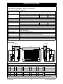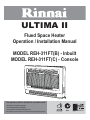
1
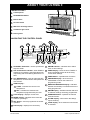
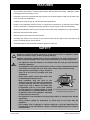
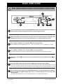
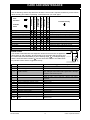
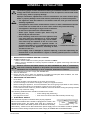
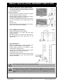
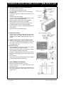
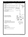
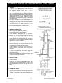
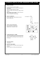
ULTIMA II
Flued Space Heater
Operation / Installation Manual
MODEL REH-311FT(B) - Inbuilt
MODEL REH-311FT(C) - Console
This appliance shall be installed in accordance with:
• Manufacturer’s Installation Instructions
• Current AS/NZS 3000 and AS/NZS 5601
• Local Regulations and Municipal Building Codes
This appliance must be installed, serviced and removed by an authorised person.
All Rinnai gas products
are A.G.A. certified.
Distributed and serviced in Australia under a Quality
System certified as complying with ISO 9001 by
SAI Global
INSTALLATION REQUIREMENTS
This heater must be installed by an authorised person. The installation must conform to local regulations.
The installation must also comply with the instructions supplied by Rinnai.
Service and removal must be carried out by an authorised person.
CERTIFICATION
The Rinnai REH311FT has been certified by the Australian Gas Association.
The AGA Certification Number is shown on the appliance dataplate.
No parts or functions should be modified or permanently removed from the heater.
Please keep these instructions in a safe place for future reference.
Rinnai Australia
i
Ultima II Operation Manual
OPERATION
INSTALLER: Go to page 15 for Installation Instructions
NOTE
ABOUT YOUR ULTIMA II ...........................................................................................1
DESIGN LAYOUT......................................................................................................................... 1
NAVIGATING THE CONTROL PANEL ........................................................................................ 1
FEATURES ..................................................................................................................2
SAFETY .......................................................................................................................2
IMPORTANT POINTS .................................................................................................3
BASIC USER GUIDE...................................................................................................5
HOW TO OPERATE THE HEATER ............................................................................6
TO TURN THE HEATER ON........................................................................................................ 6
TO ADJUST SET TEMPERATURE.............................................................................................. 6
TO TURN THE HEATER OFF...................................................................................................... 6
MODES TO DELIVER COMFORT AND ECONOMY................................................................... 7
GAS MODE .................................................................................................................................. 7
GAS / ECON MODE (ECONOMY MODE) ................................................................................... 7
GAS / ECON / AUTO OFF MODE................................................................................................ 7
SELECTING MODES ................................................................................................................... 7
TIMER OPERATION....................................................................................................8
CLOCK AND DUAL TIMERS........................................................................................................ 8
SETTING THE CLOCK................................................................................................................. 8
PROGRAMMING TIMERS ........................................................................................................... 9
OPERATING TIMERS ................................................................................................................ 10
PREHEAT................................................................................................................................... 10
LOCK AND OTHER SAFETY DEVICES...................................................................11
USING THE OVERRIDE FUNCTION ........................................................................................ 11
USING THE LOCK FUNCTION.................................................................................................. 11
SAFETY DEVICES ..................................................................................................................... 11
CARE AND MAINTENANCE.....................................................................................12
CLEANING FILTERS, GRILLES AND LOUVRES...................................................................... 12
SERVICE .................................................................................................................................... 12
TROUBLE SHOOTING CHECKLIST ......................................................................................... 13
ERROR CODES ......................................................................................................................... 13
INSTALLATION .........................................................................................................15
SPECIFICATIONS .....................................................................................................28
PRODUCT SPECIFICATIONS ................................................................................................... 28
DIMENSIONS ............................................................................................................................. 28
CONTACT INFORMATION ......................................................................................29
Rinnai Australia
ii
Ultima II Operation/Installation Manual
ABOUT YOUR ULTIMA II
DESIGN LAYOUT
4
1
Control panel
2
STANDBY/ON button
3
Burner filter
4
Air inlet louvre
5
Warm air discharge louvre
6
Thermistor grill cover
1
2
7
3
6
5
7
Dress guard
NAVIGATING THE CONTROL PANEL
25
15
19
16
14
20
10
18
8
timer
su
GAS ECON
23
24
22
9
i0:30am
AM PM
AUTO OFF
13
21
12
17
2
11
2
STANDBY / ON button - used to operate and
stop the heater.
17
AM/PM indicator - indicates AM or PM of
clock or timer settings.
8
ON / Combustion indicator - when GREEN
appliance is in standby, when RED the burner
is operating and when flashing RED there is a
fault.
18
TIMER display - when the word ‘TIMER’ is
shown the display panel will be showing
current timer settings.
19
TIMER button - operates timer functions.
9
UP / DOWN button - used to adjust the SET
temperature, clock and timers and operate the
lock function.
20
PROGRAM display - when the word
‘PROGRAM’ is shown the heater is in
programming mode.
10
TEMP display -
21
WEEKDAY/WEEKEND display - Indicates
whether the weekday or weekend timers are
being programmed.
22
AM/PM display - indicates whether AM and/
or PM timer settings are being programmed.
11
CURR - indicates the current room
temperature.
12
SET - indicates the desired room
temperature programmed by the user.
13
Clock display - displays current time.
23
14
MODE display - indicates which mode the
heater is operating in.
OVERRIDE button - operates the manual
override function.
24
SET button - used to programme the heater
operation.
FILTER display - when shown the filter(s)
require cleaning.
25
LOCK display - when shown the lock function
is activated.
15
16
DAY display - displays the current day.
Rinnai Australia
1
Ultima II Operation Manual
FEATURES
•
The Rinnai Ultima II is one of the most efficient gas space heaters available in Australia.
This has been achieved by combining good design with the latest technology, making the heater
both highly efficient and easy to use.
•
Downflow Convection operation and large capacity fan ensures effective heating to all parts of the
room and reduces stratification.
•
30 MJ/h input, large enough to suit most domestic applications.
•
Ignition is fully automatic and the burner is continuously monitored by an electronic flame failure
system. If the flame is extinguished during operation, the gas supply is shut off immediately.
•
Electronic temperature controls ensure that the room stays at the temperature you have selected.
•
Electronic dual ON and OFF timers.
•
Filters to protect the burner from dust and lint.
•
Automatic fan switch to turn the fan on and off and match the fan speed to the heat input at all
times, increasing efficiency and comfort.
•
Overheat switches avoid hazards should the appliance overheat.
SAFETY
Failure to comply with these instructions could result in a fire or explosion, which
could cause serious injury, death or property damage.
CAUTION
IMPORTANT
Improper installation, adjustments, service or maintenance can cause serious injury,
death or property damage. Such work must be performed by an authorised person.
• The appliance must be installed in accordance with the local gas and electrical
authority regulations.
• This appliance must not be installed where curtains or other combustible materials
could come into contact with it. In some cases curtains may need restraining.
• This appliance discharges a large volume of
warm air at low level to provided even heat
distribution.
150mm
• Some nylon carpets contain dyes which may
be affected by the warm air flow.
• Heat emanating from the front of this
appliance may over time affect the appearance
of some materials used for flooring such as
carpet, vinyl, cork or timber. This effect may
be amplified if the air in the room contains
cooking vapours or cigarette smoke. To avoid
this possibility, it is recommended that a mat
be placed in front of the appliance, extending
at least 750 mm in front of it.
150mm
150mm
1000mm
The above diagram shows the clearances required
around this heater whilst in operation
• The appliance is not intended for use by young children or infirm persons without
supervision.
• Young children should be supervised to ensure they do not play with the
appliance.
• If the supply cord is damaged or requires replacing, it must be replaced by the
manufacturer or the manufacturer's agent or similarly qualified person in order to
avoid a hazard.
Rinnai Australia
2
Ultima II Operation Manual
IMPORTANT POINTS
The appliance is not intended for use by young children or infirm persons without supervision.
Young children should always be supervised to ensure that they DO NOT play with the appliance.
DO NOT allow children or elderly persons to sleep in the warm air discharge from the heater.
DO NOT sit on this heater.
DO NOT post or allow children to post articles into the louvres of the heater.
DO NOT cover or place articles on this heater.
DO NOT place articles in front of the louvres
.
Keep heater away from flammable materials. Combustible materials must not be placed where the
heater could ignite them.
DO NOT place containers of liquid on top of the heater. Water spillage can cause extensive damage to
the appliance and create an electrocution hazard.
DO NOT spray aerosols near this heater while it is in use. Most aerosols contain butane gas which can
be a fire hazard if used near this heater when it is in use.
Use of aerosols, paint, polishes etc. whilst this heater is in use may also cause unpleasant smells.
Rinnai Australia
3
Ultima II Operation Manual
IMPORTANT POINTS
It is recommended that a dedicated 240V 10 Amp earthed power point be used with this appliance.
DO NOT use power boards or double adaptors to operate this appliance. Heater MUST NOT be
located below a power socket-outlet.
DO NOT remove the Dress Guard.
The dress guard is fitted to this appliance to reduce the risk of fire injury from burns and no part of it
should be permanently removed. It does not give full protection to young children or the infirm.
For protection of children or the infirm, a secondary guard is recommended.
When the heater is unplugged the for an extended period the clock will stop and will
need to be reset. However programmed ON/OFF times will remain in the memory.
NOTE
Turn the heater to Standby after use. DO NOT unplug the heater while it is in operation or while the
fans are still cycling.
2
Heat emanating from the front of this appliance may over time affect the appearance of some materials
used for flooring such as carpet, vinyl, cork or timber. This effect may be amplified if the air in the room
contains cooking vapours or cigarette smoke. To avoid this possibility, it is recommended that a mat be
placed in front of the appliance, extending at least 750 mm in front of it.
When the heater is operated for the first time or after long periods of non use a slight odour may be
emitted, this is normal. However if odours persist switch off the appliance and contact Rinnai.
During periods of frequent operation periods the filters should be cleaned weekly, however if the Filter
warning indicator illuminates, turn off the appliance immediately and clean filters before further use.
weehen0
AM PM
AUTO OFF
Rinnai Australia
4
Ultima II Operation Manual
BASIC USER GUIDE
Below is a guide to the basic operation of the Ultima II heater. For details on how to
use the advanced features of this appliance please read pages 6 to 11 of this manual.
NOTE
2
time
GAS ECON weehen0
AM PM
AUTO OFF
5
--:--
6
3
4
1
7
1
To turn on the heater press the STANDBY/ON button, the On/Combustion indicator
will illuminate Green (steady illumination) until the heater starts.
2
When the heater has started to heat the room the On/Combustion indicator will
change from Green to Red (steady illumination) to confirm heater operation.
3
This number indicates the selected (SET) room temperature.
(The available SET temperatures are: L = low, 16°C to 30°C in [ 1°C steps ], H = high)
4
This number indicates the current (CURR) room temperature.
(The SET temperature must be higher than this temperature for the heater to start)
5
Use the up arrow
lower it .
6
Press the SET button until the desired mode(s) are shown in the display.
(For best comfort and economy press the SET button until GAS, ECON & AUTO OFF are
all shown. The last mode(s) sellected become the default the next time the heater is used)
7
To turn off the heater press the STANDBY/ON button, the On/Combustion indicator
will go out and the digital display will revert to a CLOCK display for 10 seconds and
then go blank.
(The fan will continue to cycle for several minutes to cool the heater down)
Rinnai Australia
to raise the room temperature and use the down arrow
5
to
Ultima II Operation Manual
HOW TO OPERATE THE HEATER
TO TURN THE HEATER ON
14
18
10
Before you begin ensure that the Gas and Power
have been connected and turned on.
8
time
GAS ECON weehen0
AM PM
AUTO OFF
9
--:-13
12
11
2
The combustion chamber of this appliance requires
purging before gas flows and the burner sequence
begins. As a result the combustion fan starts several
seconds before there are any signs of ignition.
Press the STANDBY/ON button 2 once to begin the ignition sequence. The On/Combustion indicator
8 will glow green and the combustion fan will cycle to purge the combustion chamber. Once purged
burner ignition will take 5 ~ 10 seconds. The ON/Combustion indicator 8 will change to Red (steady)
after ignition has been achieved.
After ignition the appliance will begin to operate in the following factory preset manner:
• The TIME 13 / 18 will display - - : - -, to set the time see page 8.
• The temperature displays TEMP 10 and will show the current room temperature CURR 11 . The
default set temperature SET 12 will be 22°C. See below on how to adjust set temperature.
• The default operating mode is GAS 14 , see page 7 for modes of operation.
NOTE
To save energy, during standby the digital display will de-activate (go blank) after 10
seconds. Pressing the STANDBY/ON button
overrides this feature and will initiate
the ignition sequence, pressing any other button once re-activates the digital display.
When using the appliance for the first time or after long periods of non use, ignition
may not occur the first time it is operated as there may be air within the pipes. If
ignition does not occur after approximately 30 seconds the heater will cease operation
automatically. If this occurs press the STANDBY/ON button
twice to restart.
This heater may make noises after ignition/extinction. This is due to expansion and
contraction of the heater components and is normal.
The heater will not immediately ignite if the STANDBY/ON button
is pressed
straight after extinction. After approximately 20 seconds has passed, the heater will
automatically go into ignition mode.
TO ADJUST SET TEMPERATURE
The set temperature may be raised or lowered by use of the Up and Down buttons
temperature will be displayed under the SET 12 icon of the TEMP display 18 .
9
. The selected
The following set temperatures can be selected.
• 'L' for continuous combustion on the lowest burner setting, without thermostatic control.
• Thermostatic control between 16°C to 30°C in 1°C steps
• 'H' for continuous combustion on the highest burner setting, without thermostatic control.
The current room temperature 11 will display temperatures between 1°C to 30°C.
Once the temperature is set it will be stored in the memory of the microcomputer. If the temperature
is not adjusted further it will be the default setting when the appliance is next used.
Rooms may not arrive at the SET temperature due to the size and construction of the
room, location of the appliance or external temperatures.
NOTE
If the appliance does not ignite then the actual room temperature may already be
higher than the pre-set temperature.
TO TURN THE HEATER OFF
To turn the heater off while it is in operation press the STANDBY/ON button 2 located on the control
panel. The On/Combustion indicator 8 will go out and the digital display will revert to the CLOCK
display.
NOTE
After the On/Combustion indicator 8 has gone out, the appliance fan will continue to
cycle for several minutes. This is to lower the temperature within the appliance and is
normal. DO NOT disconnect the power during this time.
Rinnai Australia
6
Ultima II Operation Manual
HOW TO OPERATE THE HEATER
MODES TO DELIVER COMFORT AND ECONOMY
Your appliance has several MODE settings to choose from. The factory default mode is GAS. If the
mode is not adjusted this will be the default setting the next time the appliance is used.
As a room is warmed, the walls and ceilings are also warmed, making one feel a little warmer than
when the ceilings and walls were cold, even though the room temperature is the same. The economy
mode prevents discomfort from overheating and saves energy.
GAS MODE
Gas combustion in this mode is continuous and will adjust automatically to maintain the set
temperature. This is the factory default mode for the appliance.
GAS / ECON MODE (ECONOMY MODE)
In this mode, once the set temperature has been maintained for a period of 30 minutes, the comfort
control system will progressively lower the set temperature by 2°C over a period of 60 minutes. When
GAS / ECON mode is selected, gas combustion is continuous and will adjust automatically to maintain
the set temperature minus 2°C.
NOTE
During operation in GAS / ECON mode the current room
temperature (CURR 11 ) may be lower than the set temperature 12
(SET 12 ), however this is normal.
11
GAS / ECON / AUTO OFF MODE
In this mode, once the set temperature has been maintained for a period of 30 minutes, the comfort
control system will progressively lower the set temperature by 2°C over a period of 60 minutes. When
GAS / ECON / AUTO OFF mode is selected, gas combustion will start and stop automatically to
maintain the set temperature minus 2°C.
NOTE
During operation in GAS / ECON / AUTO OFF mode the current room
temperature (CURR 11 ) may be lower than the set temperature 12
(SET 12 ), however this is normal.
11
SELECTING MODES
The current operation mode is displayed on the digital display
select which mode the heater will use during operation.
14
and the SET button
15
is used to
15
14
GAS ECON weehen0
AM PM
AUTO OFF
timeroff
su
--:--am
The select a different mode press the SET button 15 whilst the appliance is in operation, this will cycle
the heater through the available modes as follows:
GAS ECON
AUTO OFF
NOTE
GAS ECON
AUTO OFF
GAS ECON
AUTO OFF
The MODE selected will be stored in the memory of the microcomputer. if the MODE
is not changed further it will be available as the initial setting when the appliance is
next used.
Rinnai Australia
7
Ultima II Operation Manual
TIMER OPERATION
CLOCK AND DUAL TIMERS
The setting of the Clock and programming of the Timers is done via the SET button 15 . Each press
of this button will cycle the appliance through the available clock setting and timer programming
modes.
SETTING THE CLOCK
1
2
With the heater in the STANDBY condition press the
SET button 15 once (if the digital display is blank
press the SET button 15 twice) to enter the TIME
function. The factory default clock display is SU
12:00 AM. The day indicator 16 will be flashing.
The following example will show how to set the clock
to Wednesday 8:53 pm.
16
15
GAS ECON weehen0
AM PM
AUTO OFF
After setting the day, press the SET button 15 once.
The day indicator 16 will cease flashing and the
hour digits 13 will begin to flash.
GAS ECON weehen0
AM PM
After setting the hour, press the SET button 15
once. The hour digits 13 will cease flashing and the
minute digits 13 will begin to flash.
GAS ECON weehen0
AM PM
AUTO OFF
5
After setting minutes, press the SET button 15
once. The minute digits 13 will cease flashing and
the AM/PM indicators 17 will begin to flash.
Press up or down buttons 9 to set AM or PM. For
this example PM is selected.
6
After setting AM or PM, press the SET button 9
once and then press the STANDBY/ON button 2
twice to save the new time setting. The Hour/Minute
delineator 13 will begin to flash to show that the
clock is now in operation.
NOTE
9
time
WE
9
18:00am
13
15
GAS ECON weehen0
AM PM
AUTO OFF
Press up or down buttons 9 to scroll the numbers
to set minutes. For this example 53 is selected.
timeroff
WE
i2:00am
13
15
Press up or down buttons 9 to scroll the numbers
to set the hour. For this example 8 is selected.
4
i2:00am
16
Press up or down buttons 9 to scroll to the desired
day of the week. For this example WE (Wednesday)
is selected.
AUTO OFF
3
timeroff
su
time
WE
9
18:53am
17
15
GAS ECON weehen0
AM PM
AUTO OFF
time
WE
18:53pm
9
13
GAS ECON weehen0
AM PM
AUTO OFF
time
WE
18:53pm
2
It is recommended that the electric power supply to the heater is disconnected
(unplugged) only if the heater is not going to be in use for an extended period. When
the appliance is unplugged for an extended period the clock will stop and will need to
be reset. However, timer programming will remain in the memory.
Rinnai Australia
8
Ultima II Operation Manual
TIMER OPERATION
PROGRAMMING TIMERS
1
With the heater in the STANDBY condition press the
SET button 15 until the PROGRAM indicator 20 is
shown in the display and the hour digits 13 are
flashing. The WEEKDAY 21 AM 22 timer is the
initial timer that is made available for programming.
15
22 21 20
GAS ECON weehen0
AM PM
AUTO OFF
timer on
su
i2:00am
13
2
3
4
TIMER ON - Hour. Press the up or down buttons 9
to scroll through and select the hour that the heater
timer program will start. Press the SET button 15
once to lock in the hour. The minute digits 13 will
begin to flash.
15
TIMER ON - Minutes. Press the up or down buttons
9 to scroll through and select the minutes past the
hour that the heater timer program will start. Press
the SET button 15 once to lock in the minutes. The
AM/PM digits 17 will begin to flash.
15
TIMER ON - AM/PM. Press the up or down buttons
9 to select either AM or PM. Press the SET button
15 once to lock in the AM or PM setting. The hour
digits 13 will begin to flash again.
15
13
timer on
GAS ECON weehen0
AM PM
AUTO OFF
9
16:00am
17
GAS ECON weehen0
AM PM
AUTO OFF
GAS ECON weehen0
AM PM
AUTO OFF
timer on
WE
9
16:53am
timer0ff
WE
9
10:00am
13
5
6
7
TIMER OFF - Hour. Press the up or down buttons 9
to scroll through and select the hour that the heater
timer program will finish. Press the SET button 15
once to lock in the hour. The minute digits 13 will
begin to flash.
15
TIMER OFF - Minutes. Press the up or down buttons
9 to scroll through and select the minutes past the
hour that the heater timer program will finish. Press
the SET button 15 once to lock in the minutes. The
AM/PM digits 17 will begin to flash.
15
TIMER OFF - AM/PM. Press the up or down buttons
9 to select either AM or PM. Press the SET button
15 once to lock in the AM or PM setting. The hour
digits 13 will begin to flash again.
15
13
GAS ECON weehen0
AM PM
AUTO OFF
timer0ff
WE
9
19:00am
17
GAS ECON weehen0
AM PM
AUTO OFF
timer0ff
WE
9
18:53Am
2
GAS ECON weehen0
AM PM
AUTO OFF
timer on
su
i2:00am
9
13
NOTE
Repeat steps 2 through 7 above for the setting of the WEEKDAY PM, WEEKEND AM
and WEEKEND PM timer programs as required or press the STANDBY/ON button
twice to exit.
Rinnai Australia
9
Ultima II Operation Manual
TIMER OPERATION
OPERATING TIMERS
Before a timer program can be used the heater must
be turned ON with the desired set temperature 12 and
mode of operation 14 selected. To scroll through the
available timers press the TIMER button 19 . When
the heater is awaiting timer operations to begin the
Combustion indicator 8 is illuminated Green.
1
2
3
4
5
14
GAS ECON weehen0
AM PM
AUTO OFF
To select the WEEKDAY Timer, press the TIMER
button 19 until the WEEKDAY indicator 21 is
shown. The programmed on and off times for the
timer will then appear briefly, before the display
reverts back to the clock.
19
To select the WEEKEND Timer, press the TIMER
button 19 until the WEEKEND indicator 21 is
shown. The programmed on and off times for the
timer will then appear briefly, before the display
reverts back to the clock.
19
To select both the WEEKDAY and WEEKEND
Timers, press the TIMER button 19 until the
WEEKDAY-END indicator 21 is shown. The
programmed on and off times for the timers will then
appear briefly, before the display reverts back to the
clock.
19
To return the appliance to the STANDBY condition,
press the TIMER button 19 until no timer indicators
are displayed, the On/Combustion indicator 8 will
be extinguished and the clock will be displayed to
confirm that the heater is now in the STANDBY
condition and that no timer programs are selected.
19
When the heater is operating under the control of a
timer program, the timer 21 that is in use is
displayed and the relevant AM or PM indicator 22
for the timer flashes. The clock is also displayed.
12
8
timer on
su
ii:2ipm
21
GAS ECON weehen0
AM PM
AUTO OFF
timer on
WE
ii:2ipm
21
GAS ECON weehen0
AM PM
AUTO OFF
timer on
WE
ii:2ipm
21
GAS ECON weehen0
AM PM
AUTO OFF
timer on
WE
ii:2ipm
8
timer on
WE
GAS ECON
AM PM
AUTO OFF
1ii:2ipm
2
22 21
timer on
TH
GAS ECON
AM PM
AUTO OFF
1 9:42pm
The heater continues to operate under control of the timers until timers are cancelled.
NOTE
If the STANDBY/ON button
is pressed whilst under control of the timers the heater
will be turned off and the timer programs will not operate.
PREHEAT
This function operates automatically in conjunction with the Timers.
When a Timer is selected, the heater may operate anywhere within
an hour prior to the programmed starting time of a Timer.
This function is called Pre-heat since it ensures the room reaches
the desired temperature by the On Time programmed into the
Timer(s). The room temperature is sensed one hour before the
programmed On Time.
The actual room temperature one hour prior to the programmed
starting time of a timer combined with the data from previous
operation governs exactly how long before the programmed On
Time the micro-computer will ignite the burner.
Rinnai Australia
10
Ultima II Operation Manual
LOCK AND OTHER SAFETY DEVICES
USING THE OVERRIDE FUNCTION
18
23
This function is used to manually override the current
timer controlled operation of the heater.
12
8
2
OUERI E
su
GAS ECON
AM PM
AUTO OFF
9
ii:22pm
For example:
If the heater is between the finishing and starting times of a timer program and the Override button is
pressed 23 the OVERRIDE indicator 18 will illuminate (if the digital display is blank press the
Override button 23 twice) and the heater will begin to operate and heat the room until the next timer
off operation is reached.
If the heater is between the starting and finishing times of a timer program and the Override button is
pressed 23 the OVERRIDE indicator 18 will illuminate and the heater will stop heating the room until
the next timer on operation is reached.
To cancel override and to return to Timer operation press the Override button
indicator 18 will go out.
If the STANDBY/ON button
programs will not operate.
23
again. The Override
is pressed the heater will be turned off and the timer
NOTE
USING THE LOCK FUNCTION
25
The Lock function avoids accidental operation and
prevents small children from altering settings.
GAS ECON weehen0
AM PM
AUTO OFF
timer on
su
ii:2ipm
2
9
To Activate the Lock
To activate the Lock function press both the Up and Down buttons 9 simultaneously for 3 seconds.
The function is activated immediately and the Lock indicator 25 will be illuminated.
To Deactivate the Lock
To deactivate the Lock function press both the Up and Down buttons 9 simultaneously for 3 seconds.
The Lock indicator 25 will go out to show that the Lock function is no longer active. The Lock function
can be deactivated at any time in this manner.
NOTE
If the Lock function is activated whilst the heater is in operation or in Timer mode, all
controls other than the ability to switch the appliance OFF with the STANDBY/ON
button
will be locked until the Lock is deactivated. Timer operation will not be
affected.
If the lock function is activated whilst the appliance is in the off position, all controls
will be locked until the Lock function is de-activated.
If the appliance is switched off whilst the Lock function is activated, all controls will
be locked until the Lock function is de-activated.
Lock programming (activated or de-activated) is stored in the appliance memory.
Unplugging the appliance from the power supply has no effect on Lock programming.
SAFETY DEVICES
Overheat switches
If various critical components of the heater get too hot during operation these devices turn the gas off
automatically.
Electrical fuse
The electrical circuits are protected by a fuse.
Flame failure sensor
This device automatically cuts off the gas supply to the heater in the event of a gas failure.
Power failure
In the event of a power failure or power cut, the gas valves will automatically close.
Rinnai Australia
11
Ultima II Operation Manual
CARE AND MAINTENANCE
Your heater needs very little maintenance, but the following information will help you to keep it looking
good and working efficiently.
Unplug before cleaning.
IMPORTANT
All parts of the heater can be cleaned using a soft, damp cloth.
DO NOT use solvents to clean any parts.
DO NOT spray aerosols in the vicinity of the heater whilst in operation.
DO NOT place articles on or against this heater.
DO NOT store flammable materials near this heater.
CLEANING FILTERS, GRILLES AND LOUVRES
The burner filter 3 , air inlet louvre 4 , warm air discharge louvre
be kept clear of dust or other obstructions.
4
5
and thermistor grill cover
6
must
1
7
3
6
5
Dust contamination of these parts reduces the heating effectiveness of the appliance and may require
cleaning at least once a week during the heating season to prevent blockages.
IMPORTANT
DO NOT wait for FILTER indicator 24 to
illuminate on the display of the control panel
1 on before cleaning these areas.
GAS ECON weehen0
AM PM
AUTO OFF
DO NOT use the heater with the FILTER
indicator 24 illuminated. This may cause
the appliance to overheat.
timeroff
su
i0:30am
24
SERVICE
Rinnai recommend that this appliance and installation be inspected and serviced every 2 years.
If the power supply cord or any other component of the heater are damaged, they must be replaced
by Rinnai or a suitably qualified person.
Any service or repair work should only be carried out by an authorised person. Rinnai has service and
spare parts departments nationally see back cover for contact details.
Service calls for general cleaning, maintenance and wear and tear are not necessarily
covered under the warranty. Service calls of this nature may be chargeable.
NOTE
Rinnai Australia
12
Ultima II Operation Manual
CARE AND MAINTENANCE
TROUBLE SHOOTING CHECKLIST
Not plugged in or turned off.
Mains power failure.
(Initial Install) Air in gas pipe.
Dust on air filters.
Room too large.
Air filter blocked.
Louvre obstructed.
Gas supply turned off.
Gas escape.
On Timer is set.
Lock set.
Takes a long time to
warm the room
Smell of gas
Probable
Cause
Filter Indicator
is illuminated
Combustion stops
during operation
No Display
Fault
Condition
Burners fail to ignite
Use the following chart to help determine whether a service call is required, however if you are unsure
about the way your heater is operating, contact Rinnai or your local agent.
Possible Remedy
Plug in power cord and turn power on.
Re-ignition, when power restored, page 5.
Installer to purge air from gas supply.
Clean the air filters (Weekly).
Check with retailer.
Clean the air filters (Weekly).
Remove obstruction
Turn gas supply on at the meter or cylinder.
Isolate gas supply, call Rinnai service.
Cancel timer by using the override page 11.
Cancel Lock as described on page 11.
ERROR CODES
11
8
Your heater is also fitted with self diagnostic electronics that monitor the appliance
during start-up and operation. Should a fault occur the heater will shut down and
the cause fault will be indicated by a pair of flashing digits 11 in the Digital display
and the On/Combustion indicator 8 will also flash Red. Refer to the table below
for probable cause and the suggested remedy.
Code
Probable Cause
-:- 00
Power Failure
Power Outage
11
Ignition Failure
12
Flame Failure
14
Overheat
16
31
33
35
53
61
70
71
72
Room Overheat
Room temperature Sensor Faulty
Overheat Temperature Sensor Faulty
Flue Temperature Sensor Faulty
Sparker Failure
Combustion Fan Failure
ON/OFF Switch Faulty
Solenoids Faulty
Flame Rod Faulty
Flue Blockage / Exhaust temperature
high
90
Rinnai Australia
Suggested Remedy
Press the ON/OFF button 2 twice to reset the heater.
As above.
Check gas supply is turned on, turn the heater OFF and
then ON again. If the heater fails to ignite after 4 attempts
a Service Call will be required.
As above.
Clean air inlet. If error continues a Service Call will be
required.
Lower room temperature to below 40°C.
Service Call.
Service Call.
Service Call.
Service Call.
Service Call.
Service Call.
Service Call.
Service Call.
Service Call.
13
Ultima II Operation Manual
NOTES
Rinnai Australia
14
Ultima II
INSTALLATION
GENERAL - INSTALLATION .............................................................................................................. 16
MAIN POINTS GOVERNING HEATER LOCATION............................................................................................. 16
UNPACKING THE APPLIANCE ........................................................................................................................... 16
ELECTRICAL SUPPLY......................................................................................................................................... 16
INBUILT INSTALLATION, MASONRY FIRE PLACE ......................................................................... 17
CHECK FLUEWAY ............................................................................................................................................... 17
FIT FLUE SPIGOT ................................................................................................................................................ 17
GAS INLET UNION............................................................................................................................................... 17
REMOVE GAS INLET UNION FROM HEATER ................................................................................................... 18
GAS CONNECTION POSITION ........................................................................................................................... 18
RUN GAS SUPPLY............................................................................................................................................... 18
INSTALL THE HEATER........................................................................................................................................ 19
INSTALL RADIANTS ............................................................................................................................................ 19
CHECK FOR GAS ESCAPES ............................................................................................................................. 19
CLOSE GAS SUPPLY COVER ........................................................................................................................... 19
INSTALL COWL ................................................................................................................................................... 19
TEST APPLIANCE ............................................................................................................................................... 19
INSTRUCT CUSTOMER ..................................................................................................................................... 19
CONSOLE INSTALLATION, CAVITY TWIN SKIN FLUE .................................................................. 20
CUT OPENING IN WALL...................................................................................................................................... 20
RUN GAS SUPPLY............................................................................................................................................... 20
CUT AWAY THE TOP PLATE AND ANY NOGGINS BETWEEN STUDS ........................................................... 20
LOWER TWIN SKIN FLUE DOWN CAVITY......................................................................................................... 20
INSTALL FLUE SUPPORT ................................................................................................................................... 20
FIT SEALING PLATE............................................................................................................................................ 20
FIT RECTANGULAR TO ROUND ADAPTOR ...................................................................................................... 21
GAS INLET UNION............................................................................................................................................... 21
REMOVE GAS INLET UNION FROM HEATER .................................................................................................. 21
GAS CONNECTION POSITION .......................................................................................................................... 21
INSTALL HEATER ............................................................................................................................................... 22
INSTALL RADIANTS ........................................................................................................................................... 22
CHECK FOR GAS ESCAPES ............................................................................................................................. 22
CLOSE GAS SUPPLY COVER ........................................................................................................................... 22
TEST APPLIANCE ............................................................................................................................................... 22
INSTRUCT CUSTOMER ..................................................................................................................................... 22
CONSOLE INSTALLATION, MASONRY FIRE PLACE ..................................................................... 23
PREPARE FIREPLACE ........................................................................................................................................ 23
INSTALL COWL.................................................................................................................................................... 23
GAS INLET UNION............................................................................................................................................... 23
REMOVE GAS INLET UNION FROM HEATER ................................................................................................... 24
GAS CONNECTION POSITION ........................................................................................................................... 24
RUN GAS SUPPLY............................................................................................................................................... 24
INSTALL HEATER ................................................................................................................................................ 25
INSTALL RADIANTS ............................................................................................................................................ 25
CHECK FOR GAS ESCAPES ............................................................................................................................. 25
CLOSE GAS SUPPLY COVER ........................................................................................................................... 25
TEST APPLIANCE ............................................................................................................................................... 25
INSTRUCT CUSTOMER ..................................................................................................................................... 25
INBUILT / CONSOLE COMMISSIONING ........................................................................................... 26
INBUILT / CONSOLE BURNER PRESSURE SETTING .................................................................... 27
PRODUCT SPECIFICATIONS ............................................................................................................................ 28
DIMENSIONS ...................................................................................................................................................... 28
CONTACT INFORMATION ................................................................................................................. 29
Rinnai Australia
15
Ultima II Installation Manual
GENERAL - INSTALLATION
WARNING
The following pages contain information relating to Installation and Service. Failure to
comply with these instructions could result in a fire or explosion, which could cause
serious injury, death or property damage.
Improper installation, adjustments, service or maintenance can cause serious injury,
death or property damage. Such work must be performed by an authorised person.
• The appliance must be installed in accordance with the local gas and electrical
authority regulations.
IMPORTANT
• This appliance must not be installed where curtains or other combustible materials
could come into contact with it. In some cases curtains may need restraining.
• This appliance discharges a large volume of warm air
at low level to provided even heat distribution.
150mm
• Some nylon carpets contain dyes which may be
affected by the warm air flow.
• Heat emanating from the front of this appliance may
over time affect the appearance of some materials
used for flooring such as carpet, vinyl, cork or timber.
This effect may be amplified if the air in the room
contains cooking vapours or cigarette smoke. To
avoid this possibility, it is recommended that a mat be
placed in front of the appliance, extending at least
750 mm in front of it.
150mm
150mm
1000mm
The above diagram shows the clearances required
around this heater whilst in operation
• If the supply cord is damaged or requires replacing, it must be replaced by the
manufacturer or the manufacturer's agent or similarly qualified person in order to
avoid a hazard.
1. MAIN POINTS GOVERNING HEATER LOCATION
i. Suitable Installation Type
• Ultima II Inbuilt: Suitable for masonry fireplace installations ONLY!
• Ultima II Console: Suitable for a masonry fireplace installation, or against a wall using a twin skin flue
in the wall cavity.
IMPORTANT
Ultima II Console and Inbuilt models are NOT SUITABLE for ‘built in’ installations
other than a masonry fireplace as described in this manual. They are not suitable for
installation into non masonry or ‘false’ fireplaces, bookcases or shelves.
ii. Flue connection and cowl to comply with AS/NZS 5601.
iii. Warm air distribution.
iv. Ensure that the area in which the appliance is installed has adequate fixed ventilation, this fixed
ventilation must be provided in accordance with AS/NZS 5601.
2.
•
•
•
•
•
UNPACKING THE APPLIANCE
Undo straps.
Lift carton off heater, never lift heater out of carton by top louvres.
Check for damage. If the heater is damaged, contact your supplier for advice.
Before installing this appliance, check it is labelled for the correct gas type (see label on rear of heater).
Refer to local gas authority for confirmation of gas type if you are in doubt.
For the Ultima II Inbuilt model only, before installation, remove & discard the triangular packing brackets
from rear top of the front casing.
The following additional items should be included in the carton:
•
•
Radiants (2 packs of 3)
Flue spigot and screws
•
•
Foam sealing strip (Inbuilt only)
Rear Cover and screws with wall brackets (Console only).
3. ELECTRICAL SUPPLY
The heater has a power cord with a three pin plug supplied.
Wall
Rinnai recommends that the heater be plugged into a 240V, 10A
Power
Heater
1500mm
Point
earthed power point. The power point must be a minimum of
(300mm Min)
300mm to the side of the heater (it must not be above the heater).
Alternatively - heater can be direct wired if the power supply is to be concealed. Consult a qualified
electrician if direct wiring is required as it must comply to AS/NZS 5601 and AS/NZS 3000.
Rinnai Australia
16
Ultima II Installation Manual
INBUILT INSTALLATION, MASONRY FIRE PLACE
1. CHECK DIMENSIONS OF FIREPLACE
Masonry Fireplace Dimensions
710 mm minimum
Width
w
805 mm maximum
605 mm minimum
h
Height
635 mm maximum
d
Depth
330 mm minimum
w
h
d
2. CHECK FLUEWAY
• Remove damper plate/baffle - Any damper plate or
baffle which has been installed in the chimney shall
be removed.
• Check flueway is clear of obstructions.
• Check dimensions of fireplace and if necessary
remove any protruding brickwork to give 75 mm
minimum clearance from flue spigot.
• Provide a firm, flat and sealed base for heater. A
rough base may cause rattles and affect
performance.
• Check that there are no unwanted holes or
openings in fireplace. If so these must be sealed.
• The chimney must be confirmed free of soot and
creosote that may have built up if previously used
for a solid fuel fire. Before installing the heater,
inspect the chimney, flue piping and/or solid fuel
burning fire place and remove any combustible
materials.
• A gas appliance must not be connected to a
chimney flue serving a separate solid-fuel burning
appliance.
• Peel protective backing off the foam strips supplied
with the heater.
• Attach strips supplied with the heater. The strip is
intended to form a seal between the heater and
fireplace. If an adequate seal cannot be formed
with this strip another means of sealing must be
used (e.g. fibreglass batts), between the fireplace
and the heater body.
3. FIT FLUE SPIGOT
• The flue spigot is packed separately in the carton.
• It must be fitted to all models, inbuilt and console.
4. GAS INLET UNION
• For ease of connection a combined gas inlet union/
copper elbow is provided with every heater. It is
situated at the bottom right hand side below the
control.
Rinnai Australia
17
Ultima II Installation Manual
INBUILT INSTALLATION, MASONRY FIRE PLACE
5. REMOVE GAS INLET UNION FROM HEATER
• The inlet union/elbow should be fitted to the end of
the copper supply tube before installing the heater
in the fireplace opening.
For access to union:
• Remove bottom louvre panel, 2 screws in the lower
right and left hand corners of louvres.
• Remove upper front panel, 2 screws at the bottom
right and left hand edges of the panel.
• Lift panel to disengage top and remove from heater.
• Do not lift the panel by the dress guard or top
louvres.
• Remove union.
• Ensure that removal and replacement of the bottom
panel is not obstructed by carpet etc.
6. GAS CONNECTION POSITION
• Drawing is viewed from rear of heater.
• Actual connection is on right hand side when
viewed from front.
• Dimensions are to the centre of the flare fitting on
the inlet elbow/union. Flare fitting suits 15 mm
copper tube.
7. RUN GAS SUPPLY
• Refer to AS/NZS 5601 or other approved pipe
sizing chart if in doubt about size of gas line.
• Copper supply should be run leaving a flare
connection the position shown.
• Connect the union/elbow fitting to the copper
supply with the union nut facing upwards.
• Purge supply of air and swarf.
• All foreign materials such as filings must be purged
from the gas supply, as they could cause the gas
valve to malfunction.
Don’t forget to put flare nut on tube before flaring.
NOTE
IMPORTANT
Gas pipe sizing must consider the gas input to this appliance as well as all other
gas appliances in the premises. The gas meter and regulator must be specified for
the total gas rate. Suitable sizing chart such as the one in AS/NZS 5601 should be
used.
Rinnai Australia
18
Ultima II Installation Manual
INBUILT INSTALLATION, MASONRY FIRE PLACE
8. INSTALL THE HEATER
• Feed the copper tube through the supply access
opening.
• Connect and tighten gas supply union.
• Secure heater to fireplace, there are pre-drilled
holes in the heater flanges.
• Drill additional holes if the existing ones are not in
suitable positions.
9. INSTALL RADIANTS
• Remove glass panel, install radiants as shown.
• Replace glass panel.
10. CHECK FOR GAS ESCAPES
• Use a manometer or soapy water.
• DO NOT USE A NAKED FLAME.
11. CLOSE GAS SUPPLY COVER
• This seals the heater from the chimney and prevents
chimney draughts affecting the performance of the
heater, as well as preventing the entry of debris from
the chimney.
12. INSTALL COWL
• A cowl certified for gas appliances must be installed
on all chimneys.
• Clearances to conform with AS/NZS 5601. The
minimum clearance between top of chimney and
the lowest opening in the flue cowl is 200 mm as
shown.
• Size:100 mm.
13.
•
14.
•
•
TEST APPLIANCE
See page 26.
INSTRUCT CUSTOMER
Instruct customer on operation and servicing of the
appliance.
Remind customer of dress guard requirements.
Rinnai Australia
19
Ultima II Installation Manual
CONSOLE INSTALLATION, CAVITY TWIN SKIN FLUE
1. GENERAL
• Depth of cavity wall must be at least 75 mm.
• Select position of heater and locate studs. There
must be a minimum distance of 345 mm and a
maximum distance of 550 mm between studs.
• Ensure ceiling and roof structure will not obstruct
flue.
2. CUT OPENING IN WALL
• The wall box measures 330 mm x 100 mm but the
opening required is 335 mm x 160 mm. This is to
allow for ventilation around the wall box.
• Failure to cut the correct sized hole may lead to
excessively high wall temperatures.
3. RUN GAS SUPPLY
• The gas supply should be run before installing the
heater. The easiest way is to run the supply, leaving
the end of the copper flare as shown in the
diagrams, then attach the elbow / union to the
copper supply when the heater is installed.
• Refer to an approved pipe sizing chart such as the
one in AS/NZS 5601 ‘Gas Installations’ if in doubt
about size of supply pipe.
4. CUT AWAY THE TOP PLATE AND ANY NOGGINS BETWEEN STUDS
Fit flue housing into prepared opening:
• Tabs should be fitted tightly against the plaster
board.
• Drill through flanges at stud centres and fix to wall
with 4 screws.
• The housing must be secured to the studs to allow
the outlet to protrude back into the cavity, giving the
twin skin flue a minimum clearance from plaster
board of 10 mm, excluding spacers.
5. LOWER TWIN SKIN FLUE DOWN CAVITY
• Straighten tabs at bottom of twin skin flue assembly
and lower down wall cavity to housing.
• Insert tabs in slots in housing then bend tabs to
secure flue to housing.
6. INSTALL FLUE SUPPORT
• Drop top plate flue support over top of flue, position
centrally in space between studs and secure
support in position.
7. FIT SEALING PLATE
• If flue protrudes more than 65 mm above top plate,
adaptor supports must be screwed to the flue, and
positioned so that when the sealing plate is fitted it
is 50 mm from the top of the flue.
Rinnai Australia
20
Ultima II Installation Manual
CONSOLE INSTALLATION, CAVITY TWIN SKIN FLUE
8.
•
•
•
•
•
•
•
•
•
•
•
•
FIT RECTANGULAR TO ROUND ADAPTOR
Fit adaptor to top of twin skin.
Fit 100 mm flue and approved cowl.
Flue termination above the roof must comply with
AS/NZS 5601.
Locate the longer end inside the aluminium liner of
twin skin.
Position elbow into housing.
The flue must be supported independently of the
heater to comply with AS/NZS 5601.
Attach loosely to housing with screw provided.
Measure distance from floor to flue outlet.
Adjust elbow to these dimensions, tighten screw.
Fit right and left hand rear covers to Heater.
Place top spacer (cover) in position temporarily for
wall marking.
Remove front cover and inlet union.
9. GAS INLET UNION
• For ease of connection a combined gas inlet union/
copper elbow is provided with every heater. It is
situated at the bottom right hand side below the
control.
10. REMOVE GAS INLET UNION FROM HEATER
• The inlet union/elbow should be fitted to the end of
the copper supply tube fore installing the heater in
the fireplace opening.
For access to union:
• Remove bottom louvre panel, 2 screws in the lower
right and left hand corners of louvres.
• Remove upper front panel, 2 screws at the bottom
right and left hand edges of the panel.
• Lift panel to disengage top and remove from heater.
• Do not lift the panel by the dress guard or top
louvres.
• Remove union.
• Ensure that removal and replacement of the bottom
panel is not obstructed by carpet etc.
11. GAS CONNECTION POSITION
• Drawing is viewed from rear of heater.
• Actual connection is on right hand side when
viewed from front.
• Dimensions are to the centre of the flare fitting on
the inlet elbow/union. Flare fitting suits 15 mm
copper tube.
Rinnai Australia
21
Ultima II Installation Manual
CONSOLE INSTALLATION, CAVITY TWIN SKIN FLUE
12.
•
•
•
•
•
•
•
INSTALL HEATER
Mark position of top of spacer on wall.
Fit wall clips.
Feed the copper tube through the supply access
opening.
Install heater, ensure spigot is correctly engaged
into elbow.
Replace top spacer, clipping the spacer into the
wall brackets at the same time as attaching it to the
heater.
Secure top spacer with the four screws provided.
The heater is now secured to the wall.
13. INSTALL RADIANTS
• Remove glass panel, install radiants as shown.
• Replace glass panel.
14. CHECK FOR GAS ESCAPES
• Use a manometer or soapy water.
• DO NOT USE A NAKED FLAME.
15. CLOSE GAS SUPPLY COVER
• This seals the heater from the chimney and prevents
chimney draughts affecting the performance of the
heater, as well as preventing the entry of debris from
the chimney.
16. TEST APPLIANCE
• See page 26.
17. INSTRUCT CUSTOMER
• Instruct customer on operation and servicing of the
appliance.
• Remind customer of dress guard requirements.
Rinnai Australia
22
Ultima II Installation Manual
CONSOLE INSTALLATION, MASONRY FIRE PLACE
1. GENERAL
•
•
•
•
2.
•
•
•
•
•
•
•
•
In this type of installation the fireplace is closed off
with fireproof material. The heater is placed against
the fireproof material and a hole is cut for
penetration of the flue spigot into the fireplace.
The flue spigot must have an extension added to
extend beyond overhead brickwork.The extension
must be constructed so that it prevents falling
debris entering the flue spigot. Cutting the end of
the spigot at a 45 degree angle facing downwards
will achieve this.
The spigot extension must not be extended so far
into the chimney as to cause an obstruction to the
discharge of flue gases. The minimum clearance
from the end of the spigot extension to any
obstruction is 75 mm.
Do not install heater below a wooden shelf.
PREPARE FIREPLACE
Remove any damper plates or baffles.
Check flueway is clear of obstructions.
Check fireplace dimensions and, if necessary,
remove any brickwork to provide 75mm clearance
between the end of the spigot extension and any
obstruction.
Check there are no unwanted holes or openings in
the fireplace. If so these must be sealed, so that the
fireplace is in a sound condition.
The chimney shall be confirmed free of soot and
creosote that may have built up if previously used
for a solid fuel fire. Remove combustible materials
or substances before installing the heater.
A gas appliance must not be connected to a
chimney serving a separate solid fuel burning
appliance.
Provide a firm, flat and sealed base for the heater.
A rough or uneven base may cause rattles and
affect performance.
Close off the fireplace with a fireproof material and
cut hole for flue spigot as shown.
3. INSTALL COWL
• A cowl certified for gas appliances must be installed
on all chimneys.
• Clearances to conform with AS/NZS 5601. The
minimum clearance between top of chimney and
the lowest opening in the flue cowl is 200 mm as
shown.
• Size:100 mm.
4. GAS INLET UNION
• For ease of connection a combined gas inlet union/
copper elbow is provided with every heater. It is
situated at the bottom right hand side below the
control.
Rinnai Australia
23
Ultima II Installation Manual
CONSOLE INSTALLATION, MASONRY FIRE PLACE
5. REMOVE GAS INLET UNION FROM HEATER
• The inlet union/elbow should be fitted to the end of
the copper supply tube fore installing the heater in
the fireplace opening.
For access to union:
• Remove bottom louvre panel, 2 screws in the lower
right and left hand corners of louvres.
• Remove upper front panel, 2 screws at the bottom
right and left hand edges of the panel.
• Lift panel to disengage top and remove from heater.
• Do not lift the panel by the dress guard or top
louvres.
• Remove union.
• Ensure that removal and replacement of the bottom
panel is not obstructed by carpet etc.
6. GAS CONNECTION POSITION
• Drawing is viewed from rear of heater.
• Actual connection is on right hand side when
viewed from front.
• Dimensions are to the centre of the flare fitting on
the inlet elbow/union. Flare fitting suits 15 mm
copper tube.
7. RUN GAS SUPPLY
• Refer to AS/NZS 5601 or other approved pipe
sizing chart if in doubt about size of gas line.
• Copper supply should be run leaving a flare
connection the position shown.
• Connect the union/elbow fitting to the copper
supply with the union nut facing upwards.
• Purge supply of air and swarf.
• All foreign materials such as filings must be purged
from the gas supply, as they could cause the gas
valve to malfunction.
Don’t forget to put flare nut on tube before flaring.
NOTE
IMPORTANT
Gas pipe sizing must consider the gas input to this appliance as well as all other
gas appliances in the premises. The gas meter and regulator must be specified for
the total gas rate. Suitable sizing chart such as the one in AS/NZS 5601 should be
used.
Rinnai Australia
24
Ultima II Installation Manual
CONSOLE INSTALLATION, MASONRY FIRE PLACE
8. INSTALL HEATER
•
•
•
•
•
•
Fit right and left rear covers to heater.
Place top spacer (covers) in position temporarily for
wall marking.
Attach flue spigot extension to heater.
Feed the copper tube through the supply access
opening.
Secure heater to the fireproof material using the
clips in the top spacer (covers).
Connect and tighten the gas supply.
9. INSTALL RADIANTS
• Remove glass panel, install radiants as shown.
• Replace glass panel.
10. CHECK FOR GAS ESCAPES
• Use a manometer or soapy water.
• DO NOT USE A NAKED FLAME.
11. CLOSE GAS SUPPLY COVER
• This seals the heater from the chimney and prevents
chimney draughts affecting the performance of the
heater, as well as preventing the entry of debris from
the chimney.
12. TEST APPLIANCE
•
See page 26.
13. INSTRUCT CUSTOMER
• Instruct customer on operation and servicing of the
appliance.
• Remind customer of dress guard requirements.
Rinnai Australia
25
Ultima II Installation Manual
INBUILT / CONSOLE COMMISSIONING
240V inside heater, risk of electrical shock.
CAUTION
Commissioning
1. After purging and clearing supply, connecting gas and testing for escapes, plug the heater into the
power point.
2. Remove test point screw, situated just above the barrel union on the inlet gas connection.
3. Attach manometer to test point.
4. Light the burner (See Customers Instructions page 6).
5. Check the appearance of the flame on high and low settings, there should be no flame lift or yellow
flames.
6. With the appliance operating on high confirm that incoming pressure is a least 1.13 kPa for Natural
gas or 2.75 kPa for Propane Gas.
7. Turn the heater off.
8. Remove manometer to test point and replace test point screw.
9. Carefully check for gas escapes around the test point screw.
10. Re-assemble front panels.
11. It is the responsibility of the installer to check that under normal operating conditions of the
appliance, all flue gases are exhausted to the outside atmosphere and that there is no spillage of
combustion gases into the room. Please refer to AS/NZS 5601.
12. If you are unable to get the heater to work correctly, contact Rinnai or your agent. Check “ERROR
CODES” on page 13.
13. Explain the operation and features of this appliance to the customer.
14. Explain the requirement to have the secondary guard fitted at all times to minimise the risk of injury
from burns.
15. Also explain that a secondary guard is recommended for additional protection to the young or the
infirm.
16. Explain the requirement for regular cleaning of air filters and regular servicing by an authorised
person in accordance with these instructions.
Rinnai Australia
26
Ultima II Installation Manual
INBUILT / CONSOLE BURNER PRESSURE SETTING
CAUTION
240V inside heater, caution
must be taken to avoid the risk
of electrical shock.
IMPORTANT
The gas regulator is factory pre-set. Before
making any adjustments to the appliance
regulator, check the supply pressure.
1. With the heater Turned OFF.
2. Remove test point screw
B
, of the gas control
3. Attach manometer to test point
C
A
.
.
A
4. Operate the appliance. (Start combustion).
5. Push red test button located on the top right hand side of
printed circuit board (PCB) three times. This will force the
burner to the maximum gas rate.
6. Display window should display "PH" (Forced High)
IMPORTANT
Wait for 70 seconds before proceeding as this
will allow time for the combustion of the
appliance to stabilise.
C
B
7. Check high burner pressure on manometer, for Natural Gas 0.98 kPa and for Propane Gas 2.15
kPa.
8. If burner pressure requires adjustment, alter burner pressure by pressing the "UP" button on the
display panel to increase the gas pressure, or press the "DOWN" button on the control panel to
decrease the gas pressure.
9. Push the red test button on the PCB twice.
10. Burner will modulate down to a forced low pressure (Low setting mode. 'PL' will be indicated on
the display panel
11. Check low burner pressure on manometer, for Natural Gas 0.26 kPa and for Propane Gas 0.56
kPa.
12. If burner pressure requires adjustment, alter burner pressure by pressing the "UP" button on the
display panel to increase the gas pressure, or press the "DOWN" button on the control panel to
decrease the gas pressure.
13. After checking pressure, turn the heater OFF, remove manometer and replace test point screw.
14. Carefully check for gas escapes around the test point screw.
15. Re-assemble front panels.
16. It is the responsibility of the installer to check that under normal operating conditions of the
appliance, all flue gases are exhausted to the outside atmosphere and that there is no spillage of
combustion gases into the room. Please refer to AS/NZS 5601.
17. If you are unable to get the heater to work correctly, contact Rinnai or your agent. Check “ERROR
CODES” on page 13.
18. Explain the operation and features of this appliance to the customer.
19. Explain the requirement to have the secondary guard fitted at all times to minimise the risk of injury
from burns.
20. Also explain that a secondary guard is recommended for additional protection to the young or the
infirm.
21. Explain the requirement for regular cleaning of air filters and regular servicing by an authorised
person in accordance with these instructions.
Rinnai Australia
27
Ultima II Installation Manual
SPECIFICATIONS
PRODUCT SPECIFICATIONS
Model: REH-311FTB INBUILT / REH-311FTC CONSOLE
Name: Ultima II INBUILT / CONSOLE
General description:
Gas input rate:
Gas control:
Burners
Gas Inlet:
Test Point Pressure:
Flue System:
Fan:
Flue Termination:
Combustion Fan:
Ignition system:
Power Supply:
Data Plate:
Installation type:
Weight:
Rinnai Ultima II
Radiant / Convector, Forced Exhaust, Fully Automatic Space Heater.
Natural Gas
Propane
High (MJ/hr):
30
30
Low (MJ/hr):
15
15
Rinnai Electronic control with Rinnai Solenoid Valves
Stainless Steel Ribbon Type
Barrel Union / Flare Fitting (15 mm flare connection)
High (kPa)
0.98
2.15
Low (kPa)
0.26
0.56
Forced exhaust, for twin skin flue or fireplace installation
Tangential 3 speed 32 Watt rating
An approved 100 mm cowl must be fitted to all installations.
2 - pole shaded pole induction motor (with revolution detection)
Sirocco fan (240 V)
Electronic automatic ignition
240 V / 50 Hz. Heater is fitted with a supply lead and 3 pin plug.
Replace only with Rinnai Part Number 90192303.
Bottom left hand side, behind front panel.
Console or Inbuilt
Console: 41 Kg. / Inbuilt: 38 Kg.
Rinnai reserves the right to change or modify specifications without notice.
DIMENSIONS
CONSOLE
IN B U ILT
K
K
C
A
E
I
C
D
F
G J
E
D
I
F
B
H
J
G
H
Legend
CONSOLE
A 910 mm C
265 mm
E
13.6 mm
G
600 mm
I
114 mm
B 653 mm D
24 mm
F
93 mm
H
280 mm
J 393 mm
A 910 mm C
140 mm
E
138.6 mm
G
600 mm
I
B 653 mm D
24 mm
F
93 mm
H
280 mm
J 393 mm
K
Total Installed Depth*
404 mm
INBUILT
114 mm
K
Total Installed Depth*
164 mm
*The total installation depth includes the dress guard and where applicable the rear cover kit.
Rinnai Australia
28
Ultima II Installation Manual
CONTACT INFORMATION
Australia Pty. Ltd.
Internet: www.rinnai.com.au E-mail: [email protected]
ABN 74 005 138 769
Head Office
National Help Line
10-11 Walker Street,
Braeside, Victoria 3195
P.O. Box 460
Tel: (03) 9271 6625
Fax: (03) 9271 6622
Tel: 1300 555 545*
Fax: 1300 555 655*
*Cost of a local call Higher from mobile or public phones.
Rinnai has a Service and Spare Parts network with personnel who are fully trained
and equipped to give the best service on your Rinnai appliance. If your appliance
requires service, please call Rinnai. Rinnai recommends that this appliance be
serviced every 3 years.
29
REH311-114x05 (00)
Ultima II OPINST Manual, Issue No.4 / RA 05.013 1/10/12