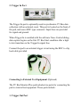
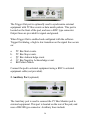
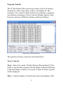
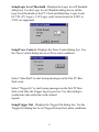
1
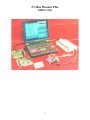
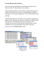
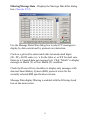
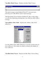
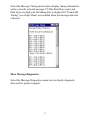
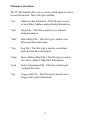
User’s Guide
MIIC-102 / PCIe / PCI / PC-CARD / ISA
I2C Bus Monitor Plus
Version 2.4
Micro Computer Control Corporation
www.mcc-us.com
The MCC I2C Bus Monitor Plus™ (#MIIC-102) I2C Bus Monitor is a
laboratory grade instrument that allows a Windows PC to monitor,
analyze, log, and display I2C Bus and derived bus protocol activity.
What is new for Version 2.4:
C
C
Windows 7 x64 - Add Windows 7 x64 support.
PCI Express (PCIe) Interface - Add PCI Express (PCIe)
Interface support.
What is new for Version 2.3:
C
C
C
C
C
C
C
Match/Non-Match Message Data Filter - Message data filter can
now display matching, or non-matching, message data.
Slave Address Map R/W/A/N Filter - Read, Write,
Acknowledgment, and Negative Acknowledgment Slave Address
Display Filter Options are now supported.
Slave Address Map Activity Monitor - Slave Address message
activity is now visible even if the Slave Address is disabled.
Message Display File - All messages displayed in the main
message window can now be logged to an ASCII text file.
Binary Data Display Option - The Binary display of message
data is now supported.
Comma-Delimited Display Option - Comma-Delimited display
of message data is now supported. Used with the Message Display
File feature (above) to generate spreadsheet compatible import
files for additional analysis.
Auto-Retry - Auto-retry on pod communication loss (CE
Support).
This user’s guide describes the installation and operation of the I2C Bus
Monitor Plus hardware and software.
I²C is a trademark of NXP (Philips) Corporation.
13-DEC-2010
Copyright© 2010 by Micro Computer Control Corporation. All rights
are reserved. No part of this publication may be reproduced by any
means without the prior written permission of Micro Computer Control
Corporation, PO Box 275, Hopewell, New Jersey 08525 USA.
DISCLAIMER: Micro Computer Control Corporation makes no
representations or warranties with respect to the contents hereof and
specifically disclaims any implied warranties of merchantability or
fitness for any particular purpose. Further, Micro Computer Control
Corporation reserves the right to revise the product described in this
publication and to make changes from time to time in the content hereof
without the obligation to notify any person of such revisions or changes.
WARNING - Life Support Applications: MCC products are not
designed for use in life support appliances, devices, or systems where
the malfunction of the product can reasonably be expected to result in a
personal injury.
WARNING - Radio Frequency Emissions: This equipment can radiate
levels of radio frequency energy that may cause interference to
communications equipment. Operation of this equipment may cause
interference with radio, television, or other communications equipment.
The user is responsible for correcting such interference at the expense of
the user.
WARNING - Electrostatic Discharge (ESD) Precautions: Any
damage caused by Electrostatic Discharge (ESD) through inadequate
earth grounding is NOT covered under the warranty of this product. See
the “Electrostatic (ESD) Precautions” section of this guide for more
information.
Printed in the United States of America
Table of Contents
System Requirements . . . . . . . . . . . . . . . . . . . . . . . . . . . . . . . . . 1
System Components . . . . . . . . . . . . . . . . . . . . . . . . . . . . . . . . . . 1
Introduction . . . . . . . . . . . . . . . . . . . . . . . . . . . . . . . . . . . . . . . 3
Features . . . . . . . . . . . . . . . . . . . . . . . . . . . . . . . . . . . . . . . . . . . 3
I2C Bus Monitor Plus Software . . . . . . . . . . . . . . . . . . . . . . . . . 4
Installation . . . . . . . . . . . . . . . . . . . . . . . . . . . . . . . . . . . . . . . . 5
ESD (Electrostatic Discharge) Precautions . . . . . . . . . . . . . . 5
Host Computer Grounding . . . . . . . . . . . . . . . . . . . . . . . . . . . . . 6
Grounding Solutions . . . . . . . . . . . . . . . . . . . . . . . . . . . . . . . . . 6
Installation - PCI Express (PCIe) Interface Card Version . 7
1. Installing the PCIe Card Driver Software . . . . . . . . . . . . . . . 8
2. Installing the PCIe Card and Driver . . . . . . . . . . . . . . . . . . . . 8
3. Configuring the PCIe Card . . . . . . . . . . . . . . . . . . . . . . . . . . 9
Installation - PCI Interface Card Version . . . . . . . . . . . . . . . 9
1. Installing the PCI Card Driver Software . . . . . . . . . . . . . . . 10
2. Installing the PCI Card and Driver . . . . . . . . . . . . . . . . . . . 10
3. Configuring the PCI Card . . . . . . . . . . . . . . . . . . . . . . . . . . 11
Installation - PC-CARD Interface Version . . . . . . . . . . . . . 11
1. Installing the PC-CARD Driver Software . . . . . . . . . . . . . . 12
2. Installing the PC-CARD and Driver . . . . . . . . . . . . . . . . . . 12
3. Configuring the PC-CARD . . . . . . . . . . . . . . . . . . . . . . . . . 12
Installation - ISA Interface Card Version . . . . . . . . . . . . . . 13
1. Installing the ISA Card Configuration Software . . . . . . . . . 13
2. Setting ISA Card Address . . . . . . . . . . . . . . . . . . . . . . . . . . 14
3. Installing the ISA Card . . . . . . . . . . . . . . . . . . . . . . . . . . . . 15
4. Configuring the ISA Card . . . . . . . . . . . . . . . . . . . . . . . . . . 15
Installing - I2C Bus Monitor Plus Software . . . . . . . . . . . . . 16
Installing - Distribution Edition . . . . . . . . . . . . . . . . . . . . . . . . 16
Installing - Demonstration/Viewer Edition . . . . . . . . . . . . . . . 16
Connecting Your PC to the Pod . . . . . . . . . . . . . . . . . . . . . . 17
Connecting to the System Under Test . . . . . . . . . . . . . . . . . 18
I2C Bus Port . . . . . . . . . . . . . . . . . . . . . . . . . . . . . . . . . . . . . . . 18
Trigger In Port . . . . . . . . . . . . . . . . . . . . . . . . . . . . . . . . . . . . . 19
Connecting to External Test Equipment . . . . . . . . . . . . . . . . . 19
Trigger Out Port . . . . . . . . . . . . . . . . . . . . . . . . . . . . . . . . . . . . 20
Auxiliary Port . . . . . . . . . . . . . . . . . . . . . . . . . . . . . . . . . . . . . . 20
Starting the I2C Bus Monitor Plus Software . . . . . . . . . . . . 22
Viewing Sample Log Files . . . . . . . . . . . . . . . . . . . . . . . . . . . . 22
Viewing Live Messages . . . . . . . . . . . . . . . . . . . . . . . . . . . . . . 22
Program Controls . . . . . . . . . . . . . . . . . . . . . . . . . . . . . . . . . 23
Trace Controls: . . . . . . . . . . . . . . . . . . . . . . . . . . . . . . . . . . . 23
Trace . . . . . . . . . . . . . . . . . . . . . . . . . . . . . . . . . . . . . . . . . . . . 23
More . . . . . . . . . . . . . . . . . . . . . . . . . . . . . . . . . . . . . . . . . . . . . 24
Halt . . . . . . . . . . . . . . . . . . . . . . . . . . . . . . . . . . . . . . . . . . . . . . 24
Clear . . . . . . . . . . . . . . . . . . . . . . . . . . . . . . . . . . . . . . . . . . . . . 24
Display [Options] . . . . . . . . . . . . . . . . . . . . . . . . . . . . . . . . . . 24
None . . . . . . . . . . . . . . . . . . . . . . . . . . . . . . . . . . . . . . . . . . . . . 24
Start, Stop, Ack, NAck and R/W . . . . . . . . . . . . . . . . . . . . . . . 24
Start Time, Byte Time, and Bit Rate . . . . . . . . . . . . . . . . . . . . 24
Filtering . . . . . . . . . . . . . . . . . . . . . . . . . . . . . . . . . . . . . . . . . . 24
Abs Time . . . . . . . . . . . . . . . . . . . . . . . . . . . . . . . . . . . . . . . . . 24
Relative Time Mode . . . . . . . . . . . . . . . . . . . . . . . . . . . . . . . . 24
Absolute Time Mode . . . . . . . . . . . . . . . . . . . . . . . . . . . . . . . . 25
Data Protocols . . . . . . . . . . . . . . . . . . . . . . . . . . . . . . . . . . . . 25
ASCII . . . . . . . . . . . . . . . . . . . . . . . . . . . . . . . . . . . . . . . . . . . . 25
HEX . . . . . . . . . . . . . . . . . . . . . . . . . . . . . . . . . . . . . . . . . . . . . 25
BIN . . . . . . . . . . . . . . . . . . . . . . . . . . . . . . . . . . . . . . . . . . . . . . 25
CD . . . . . . . . . . . . . . . . . . . . . . . . . . . . . . . . . . . . . . . . . . . . . . 25
SBS . . . . . . . . . . . . . . . . . . . . . . . . . . . . . . . . . . . . . . . . . . . . . 25
Pull-Down Menu Controls: . . . . . . . . . . . . . . . . . . . . . . . . . . 26
File|Print Setup . . . . . . . . . . . . . . . . . . . . . . . . . . . . . . . . . . . . . 26
File|Print . . . . . . . . . . . . . . . . . . . . . . . . . . . . . . . . . . . . . . . . . . 26
File|Exit . . . . . . . . . . . . . . . . . . . . . . . . . . . . . . . . . . . . . . . . . . 26
Setup|Interface Board . . . . . . . . . . . . . . . . . . . . . . . . . . . . . . . . 26
Setup|Logic Level Threshold . . . . . . . . . . . . . . . . . . . . . . . . . . 27
Setup|Trace Control . . . . . . . . . . . . . . . . . . . . . . . . . . . . . . . . . 27
Setup|Trigger Out . . . . . . . . . . . . . . . . . . . . . . . . . . . . . . . . . . . 27
Setup|Enable Bit Timing . . . . . . . . . . . . . . . . . . . . . . . . . . . . . 29
Setup|Select SBS Revision . . . . . . . . . . . . . . . . . . . . . . . . . . . 29
Setup|Open Log File for Write . . . . . . . . . . . . . . . . . . . . . . . . . 30
Setup|Open Log File for Read . . . . . . . . . . . . . . . . . . . . . . . . . 30
Setup|Open Display File for Write . . . . . . . . . . . . . . . . . . . . . . 30
Setup|Initialize External Pod . . . . . . . . . . . . . . . . . . . . . . . . . . 30
Setup|Program Settings|Save/Load/Restore . . . . . . . . . . . . . . . 31
Setup|System Diagnostics . . . . . . . . . . . . . . . . . . . . . . . . . . . . 31
Options|Show Hints . . . . . . . . . . . . . . . . . . . . . . . . . . . . . . . . . 31
Options|Set Line Length . . . . . . . . . . . . . . . . . . . . . . . . . . . . . 31
Options|Set Font . . . . . . . . . . . . . . . . . . . . . . . . . . . . . . . . . . . . 31
Filtering|Slave Address . . . . . . . . . . . . . . . . . . . . . . . . . . . . . . 32
Filtering|Message Data . . . . . . . . . . . . . . . . . . . . . . . . . . . . . . 33
View|Activity Chart . . . . . . . . . . . . . . . . . . . . . . . . . . . . . . . . . 34
View|Message Detail . . . . . . . . . . . . . . . . . . . . . . . . . . . . . . . . 34
View|Byte Mode Viewer . . . . . . . . . . . . . . . . . . . . . . . . . . . . . 35
View|Address Alias Table . . . . . . . . . . . . . . . . . . . . . . . . . . . . 35
View|Bus Status Viewer . . . . . . . . . . . . . . . . . . . . . . . . . . . . . 36
Pop-Up Menu Controls: . . . . . . . . . . . . . . . . . . . . . . . . . . . . 36
Show Message Timing . . . . . . . . . . . . . . . . . . . . . . . . . . . . . . . 37
Show Message Diagnostics . . . . . . . . . . . . . . . . . . . . . . . . . . . 37
Filename Convention: . . . . . . . . . . . . . . . . . . . . . . . . . . . . . . 38
Limited Warranty
Micro Computer Control (MCC) Corporation warrants this
product against defects in material and workmanship for a
period of ninety (90) days from the original date of purchase.
This limited warranty is not applicable to:
1.
2.
3.
4.
Normal wear and tear.
Abuse, unreasonable use, mistreatment or neglect.
Damage caused by the equipment or system with which the
product is used, or
Damage caused by modifications or repair not authorized
by MCC.
THIS WARRANTY IS EXTENDED TO THE ORIGINAL
PURCHASER ONLY AND IS IN LIEU OF ALL OTHER
WARRANTIES, INCLUDING IMPLIED WARRANTIES
OF MERCHANTABILITY AND FITNESS FOR A
PARTICULAR PURPOSE.
In no event will MCC be liable for any incidental or
consequential damages.
During the warranty period, MCC will repair, replace or refund
the purchase price of any product found defective at its option.
Returned items require an RMA (Return Material Authorization)
issued by MCC, must be carefully packaged, insured for the full
replacement value, with shipping charges prepaid, before the
return will be accepted.
System Requirements
To use the I2C Bus Monitor Plus, your PC must meet the
following requirements:
C
C
C
C
C
C
C
C
C
Windows-based PC System.
Pentium or compatible processor.
4 MB of RAM.
20 MB Free Hard Disk Space.
CD Drive.
Microsoft Windows (XP (x86), Vista and 7 (x86/x64)).
Mouse.
VGA or Better Monitor.
Interface Card Slot (PCIe 1x, PCI, PC-CARD, or ISA).
System Components
The I2C Bus Monitor Plus package includes the following
components:
1.
2.
3.
4.
5.
6.
7.
8.
9.
I2C Bus Monitor Plus Pod.
Interface Card* (PCIe 1x, PCI, or PC-CARD, or ISA).
Computer Interface Cable.
I2C Bus Clip Lead Cable (2 foot) (#CABCL).
I2C Bus Cable (4 foot) (#CAB4).
BNC to Clip Lead Trigger Cable.
International Power Supply (#MWT-5VAG).
Interface Card Driver CD (InstaCal).
I2C Bus Monitor Plus Software CD.
*NOTE: PC-CARD and ISA not supported on Vista or 7.
1
I2C Bus Monitor Plus
(#MIIC-102)
2
Introduction
The I2C Bus Monitor Plus (#MIIC-102) is a laboratory grade
troubleshooting instrument for the Inter-Integrated Circuit (I2C)
Bus developed by Philips Semiconductors. When connected to
an I2C Bus and a host computer, the I2C Bus Monitor Plus
captures and displays I2C Bus or derived bus protocol
communications.
The complete I2C Bus Monitor Plus package consists of an
external pod, interface card, connecting cables, and Windows
based software.
Features
The I2C Bus Monitor Plus includes the following features:
C
C
C
C
C
C
C
C
C
C
Non-intrusive trace of bus traffic to 400KHz.
Compatible with low voltage logic.
Microsecond time stamping on bus events and bit, byte, or
message data.
Captures Start/Stop events, device addresses, read/write
requests, acknowledgments, and data.
Display filtering on message Slave Address, R/W Access,
Acknowledgment, and up to 8 data bytes.
Log all bus activity to file.
Log all displayed messages to a file.
Trigger Input for synchronization with external event.
Trigger Output on bus events or pattern match for
triggering external test equipment.
Smart Battery System (SBS) protocol display and violation
detection.
3
I2C Bus Monitor Plus Software
MCC provides both Distribution and Demonstration/Viewer
Editions of the I2C Bus Monitor Plus software.
The Distribution Edition of the software includes full support to
capture and display bus messages. The Distribution Edition is
distributed as an integral component of the I2C Bus Monitor Plus
package.
The Demonstration/Viewer Edition of the software supports the
display of bus messages previously recorded in I2C Bus Monitor
Plus log files. The Demonstration/Viewer Edition of the
software can be used to share log files with associates, and is
available for free downloading from the MCC Web Site
(www.mcc-us.com/BMPlusDemo.htm).
4
Installation
WARNING - The instructions that follow require
certain technical skills in the field of computer
electronics. If you feel that you are not qualified to
perform the required setup and installation
procedures, we recommend the you seek assistance
from a qualified technician.
ESD (Electrostatic Discharge) Precautions
Electrostatic discharge is defined as the transfer of charge
between bodies at different electrical potentials. Electrostatic
discharge can change the electrical characteristics of a
semiconductor device, degrading or destroying it. Electrostatic
discharge also may upset the normal operation of an electronic
system, causing equipment malfunction or failure.
When connecting the I2C Bus Monitor to a host computer and a
target system, extreme care must be taken to avoid electrostatic
discharge. Failure to follow ESD protection procedures when
using the I2C Bus Monitor could damage the host computer, I2C
Bus Monitor, or the target system, and void product warranty
coverage.
5
Host Computer Grounding
Case 1 - Desktop and Single-board Computers. The chassis on a
desktop or single-board host computer must be connected to
earth ground to comply with safety regulations. If the computer
chassis is NOT connected to earth ground for some reason (i.e.,
use of a two-prong power mains plug), the host computer power
supply ground will float to some unknown voltage potential.
Case 2 - Laptop Computers. Laptop computers present special
ESD problems. Most laptop computers use an external
double-insulated mains power supply which is NOT connected
to the mains earth ground. This means that the laptop chassis is
floating at some unknown voltage potential.
In either case, upon connection to the I2C Bus Monitor and the
target system, the host computer can discharge energy through
its interface card to the I2C adapter, and on to the target system.
This discharge could damage the host computer, I2C Bus
Monitor, and the target system.
Grounding Solutions
To avoid damage to the host computer, I2C Bus Monitor, or
target system, follow these instructions:
C
C
Wear an earth grounded wrist strap, or discharge any static
charge build-up, when handling the I2C Bus Monitor or any
target system devices.
Ensure that both the host computer and target system are
connected to a common earth ground point.
6
C
C
C
C
C
Make sure that all interconnections are made BEFORE
applying power to the host computer, I2C Bus Monitor, and
target system.
If you are using a laptop computer or host computer that is
NOT connected to mains earth ground, make a hard-wired
connection from the host computer (i.e., port connector
shell) and the target system ground connector to a common
earth ground point.
Avoid plugging and unplugging system components while
the host computer or target system is powered.
Ensure that any devices connected to the target system are
properly grounded to the common earth ground point.
If unsure how to properly ground system components, seek
electrical expert help.
WARNING: Any damage caused by Electrostatic Discharge
(ESD) through inadequate earth grounding is NOT covered
under the warranty of this product.
Installation - PCI Express (PCIe) Interface Card Version
The following instructions apply to installing and configuring
the PCI Express (PCIe) version of the I2C Bus Plus interface
card in most PCs. Refer to the manual that accompanied your
PC for detailed instructions on installing cards in your PC.
The I2C Bus Monitor Plus uses a PCIe-DIO24 PCI interface
7
board and InstaCal driver software to access the external pod.
1. Installing the PCIe Card Driver Software
Insert the InstaCal CD you received with the I2C Bus Monitor
Plus into your DVD/CD-ROM drive. If the driver installer does
not start automatically, double-click on the installer
(icalsetup.exe) on the CD to begin the installation. Install the
InstaCal software by following the instructions on screen.
NOTE: Once the InstaCal driver software is installed, you must
restart your computer to complete the installation.
2. Installing the PCIe Card and Driver
This board is completely plug and play capable. To install the
interface board:
1.
Following instructions provided with your computer, turn
your computer off, unplug the power, open the case, and
insert the PCIe-DIO24 board into an available PCI-e slot.
2.
Close your computer case, plug in power, and turn it on.
3.
Windows will automatically detect the board as it starts up
and will install the driver software.
3. Configuring the PCIe Card
Configure your interface board by running the InstaCal program
via the Start|Programs|Measurement Computing|InstaCal menu.
InstaCal will automatically detect the new board. Follow the
instructions on screen to complete the board configuration and
testing.
8
Installation - PCI Interface Card Version
The following instructions apply to installing and configuring
the PCI version of the I2C Bus Plus interface card in most PCs.
Refer to the manual that accompanied your PC for detailed
instructions on installing cards in your PC.
The I2C Bus Monitor Plus uses a PCI-DIO24 PCI interface
board and InstaCal driver software to access the external pod.
1. Installing the PCI Card Driver Software
Insert the InstaCal CD you received with the I2C Bus Monitor
Plus into your DVD/CD-ROM drive. If the driver installer does
not start automatically, double-click on the installer
(icalsetup.exe) on the CD to begin the installation.. Install the
InstaCal software by following the instructions on screen.
NOTE: Once the InstaCal driver software is installed, you must
9
restart your computer to complete the installation.
2. Installing the PCI Card and Driver
This board is completely plug and play capable. To install the
interface board:
4.
Following instructions provided with your computer, turn
your computer off, unplug the power, open the case, and
insert the PCI-DIO24 board into an available PCI slot.
5.
Close your computer up, plug in power, and turn it on.
6.
Windows will automatically detect the board as it starts up
and will install the driver software.
10
3. Configuring the PCI Card
Configure your interface board by running the InstaCal program
via the Start|Programs|Measurement Computing|InstaCal menu.
InstaCal will automatically detect the new board. Follow the
instructions on screen to complete the board configuration and
testing.
Installation - PC-CARD Interface Version (XP x86 ONLY)
The following instructions apply to installing and configuring
the PC-CARD version of the I2C Bus Plus interface card in most
PCs. Refer to the manual that accompanied your PC for detailed
instructions on installing PC-CARDs in your PC.
The I2C Bus Monitor Plus uses a PC-CARD-D24CTR3 interface
board and InstaCal driver software to access the external pod.
11
1. Installing the PC-CARD Driver Software
Insert the InstaCal CD you received with the I2C Bus Monitor
Plus into your DVD/CD-ROM drive. If the driver installer does
not start automatically, double-click on the installer
(icalsetup.exe) on the CD to begin the installation. Install the
InstaCal software by following the instructions on screen.
NOTE: Once the InstaCal software is installed, you must restart
your computer to complete the installation.
2. Installing the PC-CARD and Driver
This board is completely plug and play capable. To install the
interface board:
1.
Insert the PC-CARD-D24CTR3 board into any available
PC-CARD slot.
2.
Windows will automatically detect the board as it is
inserted and will install the driver software.
3. Configuring the PC-CARD
Configure your interface board by running the InstaCal program via
the Start|Programs|Measurement Computing|InstaCal menu.
InstaCal will automatically detect the new board. Follow the
instructions on screen to complete the board configuration and
testing.
12
Installation - ISA Interface Card Version (XP x86 ONLY)
The following instructions apply to installing and configuring the
ISA version of the I2C Bus Plus interface card in most PCs. Refer to
the manual that accompanied your PC for detailed instructions on
installing cards in your PC.
The I2C Bus Monitor Plus uses a CIO-DIO24 ISA interface board
and InstaCal driver software to access the external pod.
1. Installing the ISA Card Configuration Software
Insert the InstaCal CD you received with the I2C Bus Monitor Plus
into your DVD/CD-ROM drive. If the driver installer does not start
automatically, double-click on the installer (icalsetup.exe) on the
CD to begin the installation. Install the InstaCal software by
following the instructions on screen.
13
NOTE: Once the InstaCal software is installed, you must restart
your computer to complete the installation.
2. Setting ISA Card Address
Each ISA I/O card installed in a PC uses one or more I/O address
locations within your computer's I/O address space. These address
locations are used by software running on the PC's processor in
communicating with electronics on the card.
In order to not interfere with other installed cards in the PC, each
card must use unique addresses. The interface card address
determines the card's location within your computer's I/O address
space.
Certain I/O addresses are used by the PC, others are free and may be
used by the interface card. Refer to the manual that accompanied
your PC for information regarding available address location in your
PC.
The CIO-DIO24 ISA interface card uses 4 consecutive addresses
starting with the base address selected with the ADDRESS switch
on interface card . The factory default setting for the interface card
is 300H. We recommend the default factory setting be tried first.
The ADDRESS switch may be set for addresses in the range of
000H to 3FCH. It should not be hard to find a free address area for
the card in your PC. Addresses 300H to 31FH are is a prototype
card area, and is often available for add-in cards. Addresses 390H to
39F may also be available.
The InstaCal software provides a graphical representation of
ADDRESS switch settings. We recommend that you install and run
InstaCal software before installing the interface card in your PC.
14
3. Installing the ISA Card
To install the interface board:
1.
Following instructions provided with your computer, turn your
computer off, unplug the power, open the case, and insert the
CIO-DIO24 board into any available ISA slot.
2.
Close your computer case, plug in power, and turn it on.
4. Configuring the ISA Card
Configure your interface board by running the InstaCal program via
the Start|Programs|Measurement Computing|InstaCal menu.
InstaCal will automatically detect the new board. Follow the
instructions on screen to complete the board configuration and
testing.
15
Installing - I2C Bus Monitor Plus Software
This section covers software installation procedures for the both the
Distribution and Demonstration/Viewer Editions of the I2C Bus
Monitor Plus software.
Installing - Distribution Edition
The Distribution Edition of the I2C Bus Monitor Plus software
includes full support to capture and display bus messages. This
version of the software is distributed as a component of the I2C Bus
Monitor Plus package.
To install the Distribution Edition:
1.
Insert the I2C Bus Monitor Plus software distribution CD into
your CD drive.
2.
The installation should start automatically. If it does not start,
use the Windows Explorer to double-click Setup.exe file on
the distribution CD.
3.
Follow the instructions presented on screen.
Installing - Demonstration/Viewer Edition
The Demonstration Edition of the I2C Bus Monitor Plus software
supports the display of bus messages previously recorded in log
files. This edition of the software can be used to become familiar
with I2C Bus Monitor Plus features, or to view bus message log files
captured by users of the Distribution Edition of the software.
To install the Demonstration/Viewer Edition:
16
Download the Demonstration/Viewer Edition of the software from
the MCC web site (www.mcc-us.com/BMPlusDemo.htm). Follow
the instructions on screen.
Connecting Your PC to the Pod
The I2C Bus Monitor Plus pod contains the electronic circuitry
required to capture and record bus events, and communicate these
events with the interface card and software installed in your PC.
This section describes how to connect your PC to the I2C Bus
Monitor Plus pod.
1.
Connect the previously installed interface card to the DB-37
connector at the rear of the I2C Bus Monitor Plus pod using the
interfacing cable provided.
2.
Connect the included regulated 5VDC power supply cable to
the power connector on the rear of the pod.
3.
Plug the power supply into a 120/240VAC 50/60Hz outlet.
4.
Turn the pod power on. The red power light on the front of the
pod should illuminate.
5.
To test the pod connection to your PC, run the I2C Bus
Monitor Plus Software described below and select
17
"Setup|Initialize External Pod" from the main menu. When pod
initialization is complete, the Run light on the front of the pod
will blink.
The pod is now ready to be connected to the system under test and
optionally to external test equipment. Proceed to the next section,
"Connecting to the System Under Test".
Connecting to the System Under Test
The I2C Bus Monitor Plus pod includes several ports for connecting
the pod to a system under test. These ports include:
1. I2C Bus Port
The I2C Bus port is used to connect the pod to the I2C Bus under
test. This port is located on the front of the pod, and uses an AMP
Shielded Data Link type connector. Input lines are provided for I2C
Clock, Data, and Ground, and optional System Under Test Vcc
voltage measurement.
Connect the pod to the I2C Bus under test using the I2C Bus clip lead
cable or I2C Bus cable provided.
18
2. Trigger In Port
The Trigger In port is optionally used to synchronize I2C Bus data
collection with an external event. This port is located on the front of
the pod, and uses a BNC type connector. Input lines are provided
for signal and ground.
When Trigger In is enabled with the software Trace Control dialog,
data capture begins on the first I2C Bus Start condition after a high
to low transition on the Trigger In signal line.
Connect the pod to an external trigger circuit using the BNC to clip
lead cable provided.
Connecting to External Test Equipment (Optional)
The I2C Bus Monitor Plus pod includes two ports for connecting the
pod to external test equipment. These ports include:
1. Trigger Out Port
19
The Trigger Out port is optionally used to synchronize external
equipment with I2C Bus events or data match pattern. This port is
located on the front of the pod, and uses a BNC type connector.
Output lines are provided for signal and ground.
When Trigger Out is enabled and configured with the software
Trigger Out dialog, a high to low transition on the signal line occurs
on:
a.
b.
c.
d.
e.
I2C Bus Start events.
I2C Bus Stop events.
I2C Bus Acknowledge event.
I2C Bus Negative Acknowledge event.
Bit Pattern Match.
Connect the pod to external equipment using a BNC to external
equipment cable (not provided).
2. Auxiliary Port (optional)
The Auxiliary port is used to connect the I2C Bus Monitor pod to
external equipment. This port is located on the rear of the pod, and
uses a DB-9M type connector. Auxiliary lines include:
20
Pin 1 - I2C Bus Data (SDA)
Pin 2 - I2C Bus Clock (SCL)
Pin 3 - TTL I2C Bus Clock (TSCL)
Pin 4 - TTL I2C Bus Data (TSDA)
Pin 5 - Ground (GND)
Pin 6 - Trigger Out (TOUT)
Pin 7 - Trigger In (TIN)
Pin 8 - Optional I/O (OIO)
Pin 9 - Vcc +5 Output (VOUT)
21
Starting the I2C Bus Monitor Plus Software
The best way to get familiar with the I2C Bus Monitor Plus software
is to start it up.
Even without the interface card installed or external pod connected,
you can exercise various product features by loading one of the
sample log files included with the product.
Viewing Sample Log Files
1.
From the Windows Start menu, select Programs|I2C Bus
Monitor Plus x.x|I2C Bus Monitor Plus.
2.
When using the Demonstration/Viewer Edition of the software,
use Windows Explorer to click on the BMPlus32Demo.exe file
downloaded from the MCC web site.
3.
Select "Open Log File for Read" in the "Setup" menu, and
select a pre-recorded log file. Click “Trace” to view prerecorded bus messages.
Viewing Live Messages
1.
Install the I2C Bus Monitor Plus software and hardware as
indicated in the Installation section of this user’s guide.
2.
From the Windows Start menu, select Programs|I2C Bus
Monitor Plus x.x|I2C Bus Monitor Plus.
3.
Select the desired Display (Options) and Data Protocol. Click
“Trace”, and follow the instructions on screen. Any active bus
messages will be displayed with your options.
22
Program Controls
The I2C Bus Monitor Plus software provides a rich set of features
designed to collect, time-stamp, analyze, and display I2C Bus
messages. User control of these features is provided by a graphical
user interface consisting of Trace Controls, Display Options, Data
Protocol selections, Pull-Down Menus, and Pop-Up Menus.
Main Screen - HEX Data Protocol
The operation of these controls are described below:
Trace Controls:
Trace - Enter Trace mode. The Bus Monitor Plus displays I2C Bus
traffic or log file data using the selected display format and filtering
in the main display window. If a log file is Open for Read, log data
will be displayed.
More - Continue display of log file data when main display is full.
23
Halt - Stop display of data and enter Halt mode.
Clear - Clear the main display window.
Display [Options]
None - Disables all message parsing and display activities. Use this
option along with “Open Log File for Write” to maximize pod
recording memory utilization.
Start, Stop, Ack, NAck and R/W - Controls display of I2C events.
Start Time, Byte Time, and Bit Rate - Controls display of
message timing information.
Filtering - Enables Slave Address and Message Data filtering. See
Address Map dialog and Message Data dialog for information on
establishing filtering parameters.
Abs Time - Message Start, Byte, and Bit timing can be displayed in
Relative Time or Absolute Time mode.
Relative Time Mode
Relative Mode displays timing information relative to the previous
I2C Bus event. Displayed Start timing is the time since the previous
Stop. Displayed Byte or Bit timing is the time since the previous
Start, Byte, or Bit event.
24
Absolute Time Mode
Absolute Mode displays timing information from a fixed I2C Bus
event. Displayed Start timing is the time since the first I2C Bus Start
event. Displayed Byte or Bit timing is the time since the current
message I2C Bus Start event.
Data Protocols
Captured message data can be displayed using several standard
protocols. These protocols include:
ASCII - Display printable data in ASCII format.
HEX - Display data in Hexadecimal format.
BIN - Display data in Binary format. (New for V2.3)
CD - Display data in Comma Delimited format. (New for V2.3)
SBS - Display SBS data in Smart Battery System format.
25
Main Screen - Smart Battery System Protocol
Pull-Down Menu Controls:
File|Print Setup - Setup printer.
File|Print - Print Displayed Data with option to print selected text
only.
File|Exit - Terminate program.
Setup|Interface Board - Displays the Interface Board dialog box.
Use the Interface Board dialog box to select the interface board
connected to the external pod.
26
Setup|Logic Level Threshold - Displays the Logic Level Threshold
dialog box. Use the Logic Level Threshold dialog box to set the
logic level threshold on the I2C Clock and Data lines. Logic levels
for TTL (5V Logic), 3.3V Logic, and Custom levels for 0.50V to
2.50V are supported.
Setup|Trace Control - Displays the Trace Control dialog box. Use
the Trace Control dialog box to set Trace start conditions.
Select "Auto Start" to start tracing messages on the first I2C Bus
Start event.
Select "Trigger In" to start tracing messages on the first I2C Bus
Start event after the Trigger In port goes low. Use this setting to
synchronize data collection with external
signals.
Setup|Trigger Out - Displays the Trigger Out dialog box. Use the
Trigger Out dialog box to set Trigger Out port low pulse conditions.
27
Select "Start", "Stop", "Ack", or "Nack" to generate a low pulse on
the Trigger Out port each time the selected I2C Bus event occurs.
Select "Bit Pattern" to generate a low pulse on the Trigger Out port
when the Bit Pattern Data match and Trigger Out Position
conditions occurs.
Bit Pattern data and Trigger Position selection is provided for the
I2C Bus address and first 15 data bytes within a message. Bits may
be specified as 0, 1, or Don't Care.
The Trigger Out port low pulse occurs if the Bit Pattern match is
true when the Trigger Out position occurs. Trigger Out low pulse
occurs on the I2C Bus Acknowledge bit following the Trigger Out
position byte.
The Trigger Out signal can be used to synchronize external data
collection devices such as storage scopes or logic analyzers with I2C
Bus events.
28
Setup|Enable Bit Timing - Enable collection of I2C Bus Bit Timing
information. Bit timing information is available in the "Show
Message Timing" pop-up menu described below.
Bit Timing causes the external pod to generate a 9 times increase in
data, and can result in pod data recording memory overflow on high
bandwidth or high speed bus traffic.
Setup|Select SBS Revision - Displays the Smart Battery System
(SBS) Revision dialog box.
Use this dialog box to select the SBS revision used by system
components. When displaying messages in SBS protocol, the I2C
Bus Monitor Plus software will detect and display the following
protocol violations using the selected specification revision.
SBS Protocol violation detection includes:
[VALUE RANGE VIOLATION]
[STRING LENGTH < MINIMUM]
[STRING LENGTH > MAXIMUM]
[BLOCK LENGTH < MINIMUM]
[BLOCK LENGTH > MAXIMUM]
[RESERVED BIT VIOLATION 0xXXXX]
[NO CHARGER ALARM VIOLATION]
[NO HOST ALARM VIOLATION]
[INVALID ERROR CODE 0xXXXX]
[RESERVED ERROR CODE 0xXXXX]
[RESERVED VALUE VIOLATION 0xXXXX]
[VALUE VIOLATION 0xXXXX]
29
[SINGLE BIT VIOLATION 0xXXXX]
[SLAVE ADDRESS NACK]
[0xXX RESERVED FUNCTION]
[READ ONLY ACCESS VIOLATION]
[PEC=XX CRC=XX ERR]
[PEC ACK ERROR]
[PEC NACK ERROR]
[MSG TOO LONG]
[WRITE ONLY ACCESS VIOLATION]
[UNITIALIZED READ OPERATION]
[MSG BYTES MISSING]
[INVALID REPEATED START ADDRESS]
[ALERT RESPONSE READ ONLY ACCESS VIOLATION]
For details on the SBS protocol, visit the Smart Battery
Implementors Forum at www.sbs-forum.org
Setup|Open Log File for Write - Open a log file (*.log) to record
data from I2C Bus Monitor Plus pod. Recorded log files can be
displayed with the Setup|Open Log File for Read menu item below.
Setup|Open Log File for Read - Load a previously stored file for
processing and display. The I2C Bus Monitor Plus can display log
files (*.log) previously collected from the external pod. Log files are
displayed with the currently selected display, filtering and protocol
options.
Setup|Open Display File for Write - Open a text file to record all
displayed messages. Use in combination with the Comma Delimited
data protocol option to generate comma delimited files suitable for
importing into a spreadsheet program for additional analysis. (New
for V2.3)
Setup|Initialize External Pod - Select Initialize External Pod to
initialize or re-initialize the I2C Bus Monitor Plus external pod.
Initialization also automatically occurs when performing activities
30
that require the pod.
Setup|Program Settings|Save/Load/Restore Default - Select this
menu item to Save, Load, or Restore Default I2C Bus Monitor Plus
software parameters.
Setup|System Diagnostics - Select System Diagnostics display
system diagnostic data used for product support.
Options|Show Hints - Enable display of cursor sensitive help.
Options|Set Line Length - Set display line length for message
wrap.
Options|Set Font - Select display font and size.
31
Filtering|Slave Address - Displays the Slave Address Map dialog
box. (New for V2.3)
Use the Slave Address Map dialog box to select I2C messages to
display by Slave Address, Read/Write Access, and Slave Device
Acknowledgment, and to globally monitor all address activity.
Click on grid cells to access Slave Address Filter editor.
Slave Address Activity Info shows acknowledged bus messages
with a solid dot. Negative acknowledged bus messages with a
hollow dot. Selecting a grid cell clears the activity indicator.
Slave Address Map display filtering is enabled with the Filtering
check box on the main screen.
32
Filtering|Message Data - Displays the Message Data Filter dialog
box. (New for V2.3)
Use the Message Data Filter dialog box to select I2C messages to
display by data content and by protocol error detection.
Click on a grid cell to enter match data in hexadecimal digits
(00...FF), ASCII codes (i.e. 'a for the letter a), or XX for don't care.
Enter up to 8 match data per message byte. Click “Match” to display
message on Match (Y) or Non-Match (N) condition.
Check the Protocol Error checkbox to display only messages with
detected Smart Battery System (SBS) protocol errors for the
currently selected SBS specification revision.
Message Data display filtering is enabled with the Filtering check
box on the main screen.
33
View|Activity Chart - Displays the Activity Chart dialog box.
Use the Activity Chart dialog box to display a bar chart of message
activity for the top 16 most frequently used slave addresses.
View|Message Detail - Displays the Message Detail dialog box.
Use the Message Detail dialog box to display a report of message
activity for all active slave addresses.
34
View|Byte Mode Viewer - Displays the Byte Mode Viewer.
The main message screen displays filtered I2C messages upon
detecting an I2C Bus STOP event at end of message.
The Byte Mode Viewer displays unfiltered I2C Bus events as they
cross the bus, displaying message data even if the bus stalls within a
message.
View|Address Alias Table - Displays the Address Alias Table
dialog box.
Use the Address Alias Table dialog box to specify an alias name for
slave addresses. Alias names are used to customize the display of
slave addresses.
View|Bus Status Viewer - Displays the Bus Status Viewer dialog
35
box.
Use the Bus Status Viewer dialog box to view the current voltage
levels on the I2C Bus Clock, Data, and A.bV lines. This viewer is
useful in determining if the Clock or Data lines are stuck low.
Pop-Up Menu Controls:
The Pop-Up Menu is used to view details on a specific displayed
message. This menu is available on the main screen when displayed
I2C Bus messages are present and the system is in Halt mode.
To access the Pop-Up Menu, left mouse click to select a message,
then right mouse click to pop-up the menu. Left mouse click to
select a menu item.
Show Message Timing
36
Select the Message Timing menu item to display timing information
on the currently selected message. I2C Bus Start/Stop events and
Data bytes are displayed. Bit timing data is displayed if "Enable Bit
Timing" (see Setup Menu) was enabled when the message data was
collected.
Show Message Diagnostics
Select the Message Diagnostics menu item to display diagnostic
data used for product support.
37
Filename Convention:
The I2C Bus Monitor Plus uses a variety of file types to save or
record information. These file types include:
*.als
Address Alias Table File - This file type is used
to save Slave Address name aliasing information.
*.bps
Setup File - This file is used to save software
setup parameters.
*.dmf
Data Match File - This file type is used to save
Message Filter match data.
*.log
Log File - This file type is used to record data
packets from the external pod.
*.map
Slave Address Map File - This file type is used to
save Slave Address Map filter information.
*.pod
Pod Configuration File - This file contains pod
configuration data.
*.trg
Trigger Out File - This file type is used to store
Trigger Out setup information.
38
Direct Comments/Feedback to:
Attn: Product Support (#MIIC-102)
Micro Computer Control Corporation
P.O. Box 275
Hopewell, NJ 08525 USA
Voice - (609) 466-1751
Fax - (609) 466-4116
Email - [email protected]
WWW - http://www.mcc-us.com
Declaration of Conformity
This Declaration of Conformity is issued by the indicated company which is solely
responsible for the declared compliance.
Product: I2C/SMBus Monitor Plus
Product Part Number: MIIC-102
Product Description: I2C/SMBus Monitor
Applicable Directive(s): EC Directive 89/336/EEC
Compliant Standards:
EN 55022 : 1998
Emissions Standard
Conducted Emissions (Class B)
Radiated Emissions (Class B)
EN 55024 : 1998
Immunity Standard
Immunity to Radiated Electromagnetic Fields
Immunity to Fast Transient Bursts - AC Power Lines
Immunity to Conducted Field - AC Power Lines
Immunity to Voltage Dips - AC Power Lines
Immunity to Electrostatic Discharge
Test Laboratory Information:
Cass Industries Ltd., Blackbrook Trading Estate, Weybrook Road, Manchester M19 2QD,
ENGLAND.
Test Report Number: CI02486c
Test Report Date: April 27th, 2005
Technical file held by: Micro Computer Control Corporation, 83 Princeton Avenue / PO
Box 275, Hopewell, New Jersey 08525 USA, or its applicable authorized distributor or
representative.
Responsible Company: Micro Computer Control Corporation, 83 Princeton Avenue / PO
Box 275, Hopewell, New Jersey 08525 USA, or its applicable authorized distributor or
representative.
Signature of Authorized Representative:
Name: Edward Thompson
Title: President, Micro Computer Control Corporation
Date: 13-DEC-10