1
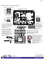
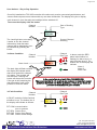
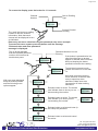
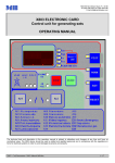
TOC-625-630
Multi-Channel Sensor Controller
CH4 H2
C2H6O
CO O 2
IAQ
NO2
LPG
CO 2
Installation and Operation Manual
Version 5
Tel: +44 (0)161 483 1415
Fax: +44 (0) 161 484 2345
Email: [email protected]
A Division of International Gas Detectors
www.sensors.ltd.uk
Page 2 of 2
INDEX
Page
3
4
5
7
8
9
10
11
12
13
14
15
15
16
16
17
18
18
19
20
21
22
22
23
24
24
25
26
27
35
CE Declaration
Gen Specifications
Main electrical Connection Points
Controller Overview
User Actions Day to Day Operation
Display Access and Menu Operation
Menu Overview
Putting into Service
Cable checks and Warm Up Sequence
Supplied Set up
Channel Setup Overview
Relay Connections
Analogue Output (mA option)
Analogue Output (Volts Option)
Analogue Output Test
Putting into Service Summary
Adding Detectors or Nodes
The FIND Command
Alarm settings
Alarm Level Setup
Alarm Type Setup
Alarm Relay
Alarm Summary
Calibrations
4-20mA Output Zero Function
4-20mA Output Calibration Function
Detector Zero Function
Detector Calibration Function
Additional Information for GSM Enabled Units
Battery Backup
Who should read this manual.
This manual is intended for use by trained installers of gas detection systems who are technically
competent and have all necessary tools to undertake installation and maintenance on this type of
equipment.
Failure to install and maintain the equipment properly can render the detector ineffective.
You should not undertake any of the procedures in this manual if you do not have access to the
correct equipment, have not undertaken training on this or similar equipment or are not technically
qualified to install this equipment.
Calibration gases and test equipment is available from Sensors.
Tel: +44 (0)161 483 1415
Fax: +44 (0) 161 484 2345
Email: [email protected]
A Division of International Gas Detectors
www.sensors.ltd.uk
Page 3 of 3
T
5
2
6
OC
R
EM
SYST
LLE
O
R
T
N
CO
2
H2SCO
CO
NO
CH4
SO2NO2
EC Declaration of Conformity
Issuers name and address:
Declares that the product listed as:
Oliver IGD Limited of
4a Pepper Rd
Stockport, SK7 5BW
United Kingdom
TOC-625
Single or Multi-Channel Detector Control Panel
Are in conformity with the provisions of the following European Directive(s) when installed, operated, serviced and maintained
in accordance with the installation and operating instructions contained in the product documentation.
2004/108/EC
2006/95/EC
EMC Directive
Low Voltage Equipment Directive (note not applicable to 24V DC Powered Versions)
And that the standards and/or technical specifications referenced below have been applied or considered.
EN 61779-1:2000
Electrical apparatus for the detection and measurement of flammable gases, general
requirements and test methods.
EN 50271:2001
Electrical apparatus for the detection and measurement of combustible gases, toxic gases or
Oxygen: requirements and tests for apparatus using software and or digital technologies.
Excluding requirements for SIL
Technical File Reference
T625-TF9
Notified Body For ATEX
and/or QAN:
Sira Test & Certification Ltd
Hazardous Area Centre,
Rake Lane
Eccleston,
Chester,
CH4 9JN.
United Kingdom
Oliver IGD Limited operate an
independently assessed ISO9001:2008
Quality Assurance System and ATEX QAN.
Quality Assurance Certificate Number
023827
Testing Agency:
CASS Industries Limited
Blackbrook Trading Estate
Weybrook Rd
Levenshulme
Manchester
M19 2QD
Quality Assurance Notification Number
SIRA 02ATEX M174
Issued on:
At Oliver IGD Limited, Stockport, SK7 5BW , United Kingdom
Declaration of Conformity in accordance with EN ISO/IEC 17050-1:2004
Signature:
Name
Andrew J Collier M.I.O.D
Position:
Managing Director
Date:
5.October 2011
Declaration Ref: TOC-625-DEC-1
Tel: +44 (0)161 483 1415
Fax: +44 (0) 161 484 2345
Email: [email protected]
A Division of International Gas Detectors
www.sensors.ltd.uk
Page 4 of 4
Standard Specifications
Do not exceed listed ratings.
Power
110/230V AC 50/60Hz 30W Standard
24V DC Option (12 to 28V DC)
Construction
ABS
Display
2 Lines x 8 Digit LCD Display
Multi-Colour Backlight (Red-Alarm, Yellow-Fault, Blue-Normal)
Outputs
2 off SPCO Relays 4A Non-Inductive
User Configurable
3 off 4-20mA Linear Outputs
User Configurable
Other I/O
Sounder 80dB @ 100mm (Mutable)
RS485 Port Modbus
Inputs
8 off Addressable Series Detectors or I/O Modules
Temperature
-5 to 55 Deg C
Humidity
0-95% RH Non-Condensing
Sealing
IP54
Failure to observe interface
ratings and environmental
operating conditions may have
an adverse affect on the
controller.
Physical Details
REAR VIEW WALL MOUNTING
POINT DETAILS 4.5mm
SCREWS
23
122
REAR VIEW
30
14
108
4 REAR ENTRY
KNOCK OUTS
20mm DIA
SIDE VIEW
PANEL MOUNT VERSION (CLAMP)
FRONT VIEW
Optional Panel Mounting Kit
PN 5686401
84
79
18
PANEL CUT OUT
TOC -625
ALARM
2 1
GAS DETECTION SYSTEM
FAULT
141 136
SELECT
POWER
201
Optional Battery Backup Kit
PN 5686601
BOTTOM VIEW
4 HOLES DIA 20mm
24
30
30
196
30
50
Note this module uses the
same style enclosure as the
TOC-625 and houses
batteries and charge control.
It is usually mounted below
the TOC-625 and is supplied
with all required connectors.
PANEL CUT OUT
Tel: +44 (0)161 483 1415
Fax: +44 (0) 161 484 2345
Email: [email protected]
A Division of International Gas Detectors
www.sensors.ltd.uk
Page 5 of 5
NOTE
Main power connections should only be made by a qualified electrician. Mains power should be fed via a fused
spur.
The following information shows the main electrical connection points labelled as points 1, 2 and 3. These
points are referred to in the manual supplied. When installing ensure you have the full manual available. This
page is also supplied inside the TOC-625 enclosure as a quick reference for site engineers. If you do not have
the full manual a copy is available on the Sensors website at www.sensors.ltd.uk
Electrical Details Figure 1 110/230V AC Operation
Analogue Output Interfaces
1
+24V DC
0V DC
mA Sig 1
mA Sig 2
mA Sig 3
Front View Cover Open
Note as standard mA
outputs are set. These
can be re-configured
as 0-10V signals
Mains Power
Connector
110/230V AC 50/60Hz
2
RL
2
RL
1
L nc N nc E
RS485 Modbus
Comms Port
0V DC
A
B
24V DC
1
Connect to detectors and nodes
using 4 core 1.5mmSQ CY style
cable or FP200 style cable as
appropriate. Cable screens
should be terminated as
indicated
Connect up to 8 addressable
devices. These can be Gas
Detectors or by using the
available I/O Nodes any 4-20mA
Device such as pressure or
temperature transmitters, read
these back to the control panel
as any other detector and set
alarms as required.
Detector I/O Interface
0V DC A B 24V DC
SCRN 0V DC A B 24V DC
Detector
SCRN 0V DC A B 24V DC
SCRN 0V DC A B 24V DC
24V DC
Input 1
Input 2
0V DC
I/O Node
Relay 1
Relay 1
Relay 2
Relay 2
SCRN 0V DC A B 24V DC
3
Connections common
to each of the two relay
outputs. Note relays
Normally Open
are normally energised
Common
for fail safe operation in
Normally Closed
service. Diagram
shows de-energised
state.
Gas detectors count as one device,
there can be any mix of gas detector
types on the highway. For example
Flammable Gas Detectors, Carbon
Monoxide, Oxygen etc.
Each I/O Node counts as one
device and can be used to
interface to analogue devices
and provide additional relay
outputs where they are
needed to control items such
as beacon-sounders,
solenoids or interfaces to fire
panels. Depending on
loading external power may
be required.
Tel: +44 (0)161 483 1415
Fax: +44 (0) 161 484 2345
Email: [email protected]
A Division of International Gas Detectors
www.sensors.ltd.uk
Page 6 of 6
Electrical Details Figure 2 24V DC Operation
Analogue Output Interfaces
1
+24V DC
0V DC
mA Sig 1
mA Sig 2
mA Sig 3
Front View Cover Open
DC
24V DC
12-28V
RL
2
RL
1
24V DC
0V DC
2
0V DC
Power
Connector
12 to 28V DC
0V DC
Note as standard mA
outputs are set. These
can be re-configured
as 0-10V signals
Fused at 3.15A
0V DC
A
B
24V DC
1
Connect to detectors and nodes
using 4 core 1.5mmSQ CY style
cable or FP200 style cable as
appropriate. Cable screens
should be terminated as
indicated
Connect up to 8 addressable
devices. These can be Gas
Detectors or by using the
available I/O Nodes any 4-20mA
Device such as pressure or
temperature transmitters, read
these back to the control panel
as any other detector and set
alarms as required.
RS485 Modbus
Comms Port
Detector I/O Interface
0V DC A B 24V DC
SCRN 0V DC A B 24V DC
Detector
SCRN 0V DC A B 24V DC
SCRN 0V DC A B 24V DC
24V DC
Input 1
Input 2
0V DC
I/O Node
Relay 1
Relay 1
Relay 2
Relay 2
SCRN 0V DC A B 24V DC
3
Connections common
to each of the two relay
outputs. Note relays
Normally Closed
are normally energised
Common
for fail safe operation in
Normally Open
service. Diagram
shows de-energised
state.
Gas detectors count as one device,
there can be any mix of gas detector
types on the highway. For example
Flammable Gas Detectors, Carbon
Monoxide, Oxygen etc.
Each I/O Node counts as one
device and can be used to
interface to analogue devices
and provide additional relay
outputs where they are
needed to control items such
as beacon-sounders,
solenoids or interfaces to fire
panels. Depending on
loading external power may
be required.
Tel: +44 (0)161 483 1415
Fax: +44 (0) 161 484 2345
Email: [email protected]
A Division of International Gas Detectors
www.sensors.ltd.uk
Page 7 of 7
Controller Overview
Internal Sounder 85dB
Sounds on alarm 1 or 2 activation
and can be muted
Colour Backlit LCD Display
Flashes Red on alarm
Flashes Yellow on Fault Detection
Blue during menu operation
Note the back light is off in normal operation and
is on during an alarm, fault detected or when editing
or checking.
Alarm Indicator LED (Red)
Flashes on Alarm Level 1
Continuous on Alarm Level 2
TOC -625
ALARM
2 1
GAS DETECTION SYSTEM
FAULT
SELECT
Fault Detected
Indicator LED (Yellow)
POWER
Power LED (Green)
Selector Button
Typical display during warm up
On initial power up the backlight will perform the
following cycle:
Backlight cycles: green-yellow-red
WARMUP
600s
The display then shows:
Software Version
Software checksum and date
Connected sensor info
Finally a countdown starts to enable connected
sensors to stabilise prior to normal operation.
Tel: +44 (0)161 483 1415
Fax: +44 (0) 161 484 2345
Email: [email protected]
A Division of International Gas Detectors
www.sensors.ltd.uk
Page 8 of 8
User Actions....Day to Day Operation
Once fully installed the TOC-625 controller will continuously monitor connected gas detectors and
sensors and compare current values with any set alarm thresholds. The display will cycle to display
each channel in turn. Normally the backlight will be switched off.
To access the display click the button
Channel
Number
Gas or Reading
Type
1=FLAM
10% LEL
The back light turns on making
it easier to see the channel
information. Note that each
channel will be displayed in turn
as indicated by pressing the
button.
Current Channel
Reading
In Alarm Condition
Channel
Gas Type
Channel
Number
ALARM
2 1
1=FLAM
alarm 1
Alarm Level
FAULT
SELECT
The back light will flash red and
the display will indicate which
alarm level and which channel
is in alarm. The sounder will
also activate. Pressing the
button will silence the sounder.
If the gas is still breaching the
alarm threshold it will not be
possible to reset the alarm
In Fault Condition
POWER
In the event of alarm or fault, CALL FOR SERVICE.
The owner operator is not usually a gas engineer or competent person
as defined by Health and Safety guidelines. If there is any doubt call
your service company and get it checked.
Channel
Gas Type
Channel
Number
In FAULT mode the Yellow fault led
will either be on. The bottom line of
the display will indicate as follows:
In alarm mode the RED
alarm led will either be
flashing for alarm level 1 or
solid for alarm level 2. The
bottom line of the display will
indicate:
Alarm 1
Alarm 2
Alarm 1&2
ALARM
2 1
1=FLAM
FLT UND
FLT COM communication
error to sensors
FLT SEN Sensor Error
FLT OVR Sensor Over Range
FLT UND Sensor Under Range
FAULT
POWER
Tel: +44 (0)161 483 1415
Fax: +44 (0) 161 484 2345
Email: [email protected]
A Division of International Gas Detectors
www.sensors.ltd.uk
Page 9 of 9
To access the display press the button for 1-2 seconds
Channel
Number
Gas or Reading
Type
1=FLAMM
10% LEL
Current Channel
Reading
The back light turns on making
it easier to see the channel
information. Note that each
channel will be displayed in turn
as indicated
Data entry and menu selection using the password entry as an example.
To access the menu system press the button until the message
“Release button and enter password”
message is displayed.
The up arrow indicates
that the indicated password
number will increment at
each button press.
á
0
PASSWORD
Password Number You are
Entering
If the button is pressed twice in a
short time then two up arrows
appear to indicate auto increment.
Now just keeping the button
pressed increments the reading.
áá
50
PASSWORD
With one arrow displayed
keep the button pressed
and the following menu
options appear.
á
50
PASSWORD
To end Auto Increment mode
release the button for more than
1s.
Note auto Increment works in
menu selection as well as data
entry to speed up menu
selections. Make sure auto
increment is off when making
selections.
dec
PASSWORD
Release button to select. The arrows
now indicate down to show you are
decrementing the number
â
0
PASSWORD
inc
PASSWORD
Release button to select. The arrows
now indicate up to show you are
incrementing the number
á
0
PASSWORD
done
PASSWORD
Release button to select and enter (in
this case) the password.
cancel
PASSWORD
Release button to select and cancel
the action.
Tel: +44 (0)161 483 1415
Fax: +44 (0) 161 484 2345
Email: [email protected]
A Division of International Gas Detectors
www.sensors.ltd.uk
Page 10 of 10
Toc-625 Menu Overview
á
0
PASSWORD
100
50
Engineer Menu Options
User Menu Options
Provides access for
control panel set up and
diagnostic functions
Provides access for
maintenance functions
find
1 of 11
Use this option to
FIND connected
devices.
zero
1 of 8
Use this option to
ZERO connected
devices
edit add
2 of 11
Use this option to
change the address of
a connected device
cal
2 of 8
Use this option to
CALIBRATE
connected devices
test add
3 of 11
Use this option to test
that connected
devices communicate
correctly
Use this option to test
The relay outputs and
audio vis devices on
the controller.
Use this option to trun
the auto Check
function on a detector
channel.
Use FIX to automatically
correct any channel
errors detected during
CHECK
Use this option to test,
zero or calibrate
analogue output 1
alarm 1
3 of 8
Use this option to set
ALARM 1 level and
action
alarm 2
4 of 8
Use this option to set
ALARM2 level and
action
disable
5 of 8
Use this option to
disable a channel
contrast
6 of 8
Use this option to set
the screen contrast
test rly
4 of 11
Check
5 of 11
Fix
6 of 11
output 1
7 of 11
output 2
8 of11
Use this option to test,
zero or calibrate
analogue output 2
output 3
9 of11
Use this option to test,
zero or calibrate
analogue output 3
usr menu
10 of 11
Use this option to
move to the user
menu
exit
11 of 11
Use this option to
EXIT back to normal
operation
about
7 of 8
Use this option to view
software version etc
exit
8 of 8
Use this option to
EXIT to normal
operation
Tel: +44 (0)161 483 1415
Fax: +44 (0) 161 484 2345
Email: [email protected]
A Division of International Gas Detectors
www.sensors.ltd.uk
Page 11 of 11
Putting Into Service
Note that this product should be supplied via a fused spur. Ensure cables used are suitable for both
their intended area of operation and load capability. This product should only be installed by a
competent person.
It is recommended to follow the set up sequence below when configuring and installing a control
panel from new.
Follow the cable commissioning procedure T625-700-920.PDF
if you don't have a copy of this download it from www.sensors.ltd.uk
Perform a sensor FIND and automatically install detector data.
(note panels are usually supplied pre-configured so this
many not be necessary, check shipping documentation)
Engineers Menu .... Find Option
find
1 of 9
Set the sensor channel alarm levels. User menu ... Alarm Setup Options AL1 and AL2 for each
channel.
alarm 1
3 of 8
(note panels are usually supplied pre-configured so this
many not be necessary, check shipping documentation)
alarm 2
4 of 8
Allow the system to run for at least a few hours then:
Zero each connected detector.
User Menu ZERO
zero
1 of 8
Calibrate each detector.
User Menu CALibrate
cal
2 of 8
EXIT to normal operation and check alarm operation by applying calibration gas and observing
alarm activation.
Make sure all components are communicating correctly. Engineers menu TEST ADD option.
test add
3 of 9
Tel: +44 (0)161 483 1415
Fax: +44 (0) 161 484 2345
Email: [email protected]
A Division of International Gas Detectors
www.sensors.ltd.uk
Page 12 of 12
This Section Follows the Sequence for Putting Into Service to Describe the Menu functions
Figure 1 shows the electrical connections to the Tocsin 625 controller.
Mains power is supplied via connector 2 and should be from a fused spur. This connection should be
made by a qualified electrician.
Cable Checks
Detectors are interfaced to connector 3. It is important to ensure that all connected devices are wired in
accordance with the details supplied in Figure 1 and each relevant detector or I/O node manual.
Cabling should be rigorously checked to ensure there are no cross overs or shorts before any power is
applied. If in doubt follow the cable check procedure listed in “Cable checks T625-700-920.PDF”.
Relay outputs and analogue outputs are indicated on Figure 1, connector 1 and RL1, RL2 respectively.
These should be left unplugged at this stage.
Warm Up Period
With power applied the system should undertake its power up sequence and
then commence a warm up period. The warm up period is there to allow
connected detectors to stabilise before operation. Note that certain detector
WARMUP
600s
types, Oxygen sensors in particular may take up to 2 hours to fully stabilise.
During the warm up period check that each connected detector or device has power and
communication. The following diagram shows the three main terminal PCB types for detectors and I/O
interface nodes and the relevant check points.
This LED flashes to
indicate power and
comms. With no
comms LED is on
constantly
Toc-625
Earth Point
FAULT
P Y
24V DC
B
A
GND
W
CHASS
24V DC
B
B
A
A
360
CAL
ZERO
GND
Toc-625
Addressable I/0
Port 3
CHASS
24V DC
GND
CHASS
24V DC
B
A
GND
mA
0V CONC 360 mA+ mA-
Sensor
This LED flashes to
indicate power and
comms. With no
comms LED is on
constantly
T107 Addressable
I/O Node
T106P Pellistor
Flammable Gas
Detectors
This LED flashes to
indicate power and
comms. With no
comms LED is on
constantly
T102/3 Toxic
IR/Oxygen Comms
Module
Tel: +44 (0)161 483 1415
Fax: +44 (0) 161 484 2345
Email: [email protected]
A Division of International Gas Detectors
www.sensors.ltd.uk
Page 13 of 13
With sensors connected and after the TOC-625 controller has completed its warm up the operating
system will go to normal operation mode.
Normal Operation
In normal operation mode the TOC-625 communicates to each detector or node in turn and displays the
data on screen. In normal mode the back light will switch off. Pressing the button once will activate the
back light, each button press then cycles the display through each channel.
For example a three channel system with a Flammable gas detector, a Carbon Monoxide Detector and
an Oxygen detector would read as:
Channel Number
Gas Type
1=FLAM
0% LEL
Reading
2 = CO
0 ppm
3 = O2
21% VOL
Units
Supplied Set Up
Systems supplied as a complete ‘set’ or order will normally have been set up at the factory during
final test. A set up report will be supplied with the controller to indicate how the control panel has
been configured. Where a client advises a particular alarm set up requirement this will be
incorporated. If no alarm set up is requested then systems will be shipped with alarms at 20% and
50% of detector range, rising latching alarms, for Oxygen sensors by default alarm 1 will be at 19%
and alarm 2 at 18% falling non latching alarms. For example the report the three channel discussed
above would read as follows:
Sales Order: S/36981
Channel 1
Address
Gas
Range
AL1
AL1 Type
AL1 Relay
AL2
AL2 Type
AL2 Relay
Analogue
Output
Channel
Client: A.N Other
Channel 2
4101
Methane
100% LEL
20%
Rising Latch
1
50%
Rising Latch
2
C1
Address
Gas
Range
AL1
AL1 Type
AL1 Relay
AL2
AL2 Type
AL2 Relay
Analogue
Output
Channel
TOC-625 Set Up Report
Channel 3
4102
CO
100 ppm
35
Rising Latch
1
55
Rising Latch
2
C2
Address
Gas
Range
AL1
AL1 Type
AL1 Relay
AL2
AL2 Type
AL2 Relay
Analogue
Output
Channel
4103
Oxygen
25% Vol
19%
Falling
1
18%
Falling
2
C3
Tel: +44 (0)161 483 1415
Fax: +44 (0) 161 484 2345
Email: [email protected]
A Division of International Gas Detectors
www.sensors.ltd.uk
Page 14 of 14
Channel Set Up Overview
Using channel one as an example the following diagram explains a typical channel set up.
The Channel Number as indicated on the TOC-625 display
Channel 1
Address
Gas
Range
AL1
AL1 Type
AL1 Relay
AL2
AL2 Type
AL2 Relay
Analogue
Output
Channel
4101
Methane
100% LEL
20%
Rising Latch
1
50%
Rising Latch
2
C1
The detector address for this channel. This address will be marked
on the cover of the detector itself
The gas which this channels detector measures
The measurement range for this channel
The threshold limit for alarm level 1
Alarm Action (in this case the alarm latches once the threshold is exceeded
Which relay activates when alarm 1 threshold is exceeded
The threshold limit for alarm level 2
Alarm Action (in this case the alarm latches once the threshold is exceeded
Which relay activates when alarm 2 threshold is exceeded
Which analogue output relates to this channel.
Note there are three analogue outputs available on the TOC-625
If the control panel has been shipped pre-configured then once correctly connected the system will be
operational. The controller should correctly cycle through each channel with no indicated errors.
Relay Test
test rly
7 of 9
The alarm relay outputs can now be connected (if they are being used). The relay outputs can be
forced on and off using the ‘test relay’ function (TEST RLY).
From Normal Operation press the function button until the display
release
alters to show ‘release button.
The system now requests a password. Enter 50 to enter the
á
50
PASSWORD
Engineer Menu.
Press the function button until option 7 of 9, TST RLY is displayed.
test rly
7 of 9
tst rly
release
Now hold down the button until prompted to release.
The display will now indicate Relay 1 On (and relay 1 should be
energised. At each press of the button each physical output is
energised in turn as indicated on the display as:
RELAY 1
ON
RELAY 2
ON
BUZZER
ON
LED PWR
ON
LED FLT
ON
LED AL
ON BACK RED
ON BACK
Each button press cycles through
the displays as listed. To exit, press
and hold the button until prompted
to release
ON
A Division of International Gas Detectors
GRN
BACK blu
ON
Tel: +44 (0)161 483 1415
Fax: +44 (0) 161 484 2345
Email: [email protected]
www.sensors.ltd.uk
Page 15 of 15
Relay Connection
As standard the TOC-625 controller is equipped with two relay outputs. The function of these two relay
outputs can be user configured and is discussed in a later section. The relays are rated to operate 4A
non inductive loads. Typical wiring arrangements are indicated below and show typical methods to
protect the relays during installation.
24V DC
TOC-625
Relay
Output
Example fit protection
diodes when switching
external DC loads.
Normally Open
Common
Normally Closed
A2
A1
0V DC
TOC-625
Relay
Output
~
~
Normally Open
Common
Normally Closed
A2
A1
Example fit protection
supressors when switching
external AC loads typical
device Farnell Ref 1438460
(0.22uF 47R X1)
Example showing typical
connection to a fire system.
TOC-625
Relay
Output
Normally Open
Common
Normally Closed
Out
Return
External E-Stop
Fire Panel Interface
Analogue Outputs (mA)
As standard the TOC-625 is equipped with three analogue outputs. By default these are configured
as 4-20mA current outputs. By request these can be set to 0-10V DC outputs during production. This
is a factory only setting. The following diagrams indicate the connections
mA Analogue Output Interfaces
1
+24V DC
0V DC
mA Sig 1
mA Sig 2
mA Sig 3
TOC-625 Analogue
Outputs
0V DC
Input 1
Ώ
Ώ
Input 2
Input 3
Ώ
Chassis Gnd
800
R (Ohms)
at Interface
Panel
200
Allowable
Operating
Region
Ώ
18
28
TOC-625
DC SUPPLY
VOLTS
Typical Interface Panel
Note this diagram shows the use of screened
cabling when interfacing signal cables. Signal
cables should be segregated from power and
control cables for best results.
Tel: +44 (0)161 483 1415
Fax: +44 (0) 161 484 2345
Email: [email protected]
A Division of International Gas Detectors
www.sensors.ltd.uk
Page 16 of 16
Analogue Outputs (Voltage)
If requested at the time of ordering the TOC-625 can be supplied with its analogue outputs reconfigured as 0-10V DC. The following diagrams indicate the connections
0-10V Analogue Output Interfaces
1
+24V DC
0V DC
V Sig 1
V Sig 2
V Sig 3
TOC-625 Analogue
Outputs
0V DC
Input 1
Input 2
Input 3
Chassis Gnd
Typical Interface Panel
Note this diagram shows the use of screened cabling when interfacing signal cables.
Signal cables should be segregated from power and control cables for best results.
Testing Analogue Outputs
output 1
4 of 9
output 2
5 of 9
output 3
6 of 9
The operating system has a simulation mode for the analogue output channels. This allows the
commissioning engineer to force a signal output to prove correct interfacing at the host system.
From Normal Operation press the function button until the display
release
alters to show ‘release button.
The system now requests a password. Enter 50 to enter the
á
50
PASSWORD
Engineer Menu.
Press the function button until the required option, OUTPUT 1, 2 or
output 1
4 of 9
output 1
release
3 is displayed. Now hold down the button until prompted to
release.
In this example output 1 will be tested.
Press the button until TEST is indicated and hold until prompted to
release.
ZERO
CLICK TO
CAL
CLICK TO
The display now shows a mV or mA output reading which can be
TEST
CLICK TO
increased or decreased as desired during testing as follows (mA
output shown)..
Indicates each button
click will increase the
reading/output
á
8
test
Current
Reading
To decrease the
reading press and
hold the button.
The display
cycles through the
following options
â
dec
test
inc
test
done
test
cancel
test
test
The down arrow now
indicates each button press
will decrease the reading. In
a similar manner select done
when finished
Release the button when the
desired option is displayed
A Division of International Gas Detectors
8
Tel: +44 (0)161 483 1415
Fax: +44 (0) 161 484 2345
Email: [email protected]
www.sensors.ltd.uk
Page 17 of 17
Putting into Service Test Schedule
In conclusion by following the steps discussed your checklist for putting into service should be:
1
Ensure the mains power supply is via a fused spur and installed in accordance with local
installation wiring regulations.
Check cable and glands are of suitable type for both the area of application and load carrying
capacity.
2
Ensure terminations via glands provide a positive seal.
Leave all interfaces unplugged and check installation cabling terminations following IGD
publication ref “Cable checks T625-700-920.PDF”.
3
Check the shipping TOC-625 SET UP REPORT to check how the controller and interfacing
detectors and nodes have been configured. Ensure that the detector addresses match the
document.
4
Plug in the connector 3 and power up the system. Check that all connected devices indicate
that they have power and are communicating correctly.
5
Allow at least 1 hour for the detectors to correctly warm up and stabilise.
6
During this period, if the relay outputs are being used check the cabling then plug in and test
using the TST RLY function the relay action.
7
During this period if the analogue outputs are being used check the cabling to connector 1 ,
plug in and test using the OUTPUT 1, 2 or 3 functions.
8
After warm up is complete use instrument air or Nitrogen as appropriate to check the detector
zero reading. Adjust if necessary (see later “zero and calibration function” section).
9
After warm up is complete use a suitable known calibration gas to check the detector calibration
reading. Adjust if necessary (see later “zero and calibration function” section).
10 Complete any site paperwork as necessary and instruct the site responsible person regarding
day to day operation (see later section “ user operation “).
11 Use the CHECK function to ensure detector channels are correctly set up and calibrated (see
section Addendum 1).
In the event that the controller needs amendment to set up follow the instructions in the following
sections.
a) Adding detectors or nodes to the controller or complete set up
b) Adding or changing alarm levels
c) Assigning relay outputs
d) Zero and Calibration Function (detectors)
e) Zero and Calibration Function (analogue outputs)
Tel: +44 (0)161 483 1415
Fax: +44 (0) 161 484 2345
Email: [email protected]
A Division of International Gas Detectors
www.sensors.ltd.uk
Page 18 of 18
Adding detectors or nodes to the controller or complete set up
If you need to either:
1. Perform a complete new set up
2. Add or remove detectors from a system
3. Change the type of sensors connected to a system
Then presuming the system is correctly installed and cabled the process would be as follows:
1. Use the FIND command to discover connected devices and install them to the controller
2. Set up the required alarm levels and relay actions
3. Test using zero and calibration gases
The following dialogues describe each function to use
The FIND Command
find
1 of 9
As previously described enter password mode and enter password 50 to gain access to the
engineers menu. The first menu option (menu option 1 of 9) is the FIND menu. To run this option the
detectors must be correctly connected to the controller and displaying green power LED function as
a minimum (some of the green power LED’s may be flashing if detectors already have
communication.) The FIND function then works in the following manner
find
1 of 9
1
find
Release
Display indicates devices found so far
Display indicates % progress
3
To store or abort the data press and
s=2 40%
hold the button until prompted to
checking
release. The first option is NO to
1 = 4101
store
data, pressing the button
found= 2
changes
this to YES to store data
2 = 4101
and vice versa. With the desired
found= 2
2
option displayed press and hold the
2 = 4101
button until prompted to release.
Release
When the discovery process is
no
complete the display indicates
Release
how many sensors have been
yes
found. The system also indicates
Release
the first found address. Each
saved=2
button press then indicates each
passed
found device address in turn.
4
Press and hold button
until prompted to
release. The system
starts discovering
connected devices
If the YES option to store data
was selected then the number
of saved devices is shown on
screen and passed of fail to
indicate the status of the
update
Tel: +44 (0)161 483 1415
Fax: +44 (0) 161 484 2345
Email: [email protected]
A Division of International Gas Detectors
www.sensors.ltd.uk
Page 19 of 19
Once the correct number of devices (either detectors or nodes) have been found and saved
(installed). Then the alarm levels can be set in the following manner.
From the TOC-625 SET UP REPORT it can be seen that each connected and installed detector or
channel can have two alarm levels set. These can be different for each device. For example a two
channel system for Methane and Carbon Monoxide may have Alarm 1 level for Methane at 20%
LEL and Alarm 1 level for Carbon Monoxide set at 35ppm.
Sales Order: S/36981
Channel 1
Address
Gas
Range
AL1
AL1 Type
AL1 Relay
AL2
AL2 Type
AL2 Relay
Analogue
Output
Channel
Client: A.N Other
Channel 2
4101
Methane
100% LEL
20%
Rising Latch
1
50%
Rising Latch
2
C1
Address
Gas
Range
AL1
AL1 Type
AL1 Relay
AL2
AL2 Type
AL2 Relay
Analogue
Output
Channel
TOC-625 Set Up Report
Channel 3
4102
CO
100 ppm
35
Rising Latch
1
55
Rising Latch
2
C2
Address
Gas
Range
AL1
AL1 Type
AL1 Relay
AL2
AL2 Type
AL2 Relay
Analogue
Output
Channel
Note in this example that either channel alarm level 1 sets off relay 1 on the controller once the
set threshold is exceeded. By default once the FIND function has been run and detectors
installed the alarm levels will be preset at 20 and 50 % of the detector or channels range and the
alarm action will be rising latching.
Alarm levels are set by the following method:
Tel: +44 (0)161 483 1415
Fax: +44 (0) 161 484 2345
Email: [email protected]
A Division of International Gas Detectors
www.sensors.ltd.uk
Page 20 of 20
alarm 1
3 of 8
Alarm Level Set Up
alarm 2
4 of 8
As previously described enter password mode and enter password 100 to enter the user menu.
Press the button until either menu 3 or 4 is displayed and hold the button until prompted to release.
The set up sequence for the alarm level selected is as follows:
alarm 1
3 of 8
alarm 1
release
To alter say alarm level 1
press and hold the
button on ALARM1
option until prompted to
release. Now select
which sensor or channel
you wish to set alarm
level 1 for.
This is the sensor number or channel number you
are selecting for which to enter alarm level 1.
Each button press increments the number. To
access more options press and hold the button
until prompted to release and the following menu
choices are available at each button press. Again
to select the desired option when displayed press
and hold the button until prompted to release.
á
1
sensor
dec
test
Select to DECrease the channel numbers
inc
test
Select to INCrease the channel numbers
done
test
cancel
test
Select if the correct channel number is
displayed and you want to set the alarm
level
Select to exit the sequence without making
changes
Each button press moves to the
next option. bottom line of display
scrolls “click to change selection”
LEVEL
click to
To select an option press
and hold the button until
prompted to release.
release
á
20
level
TYPE
click to
RELAY
click to
SUMMARY
click to
EXIT
click to
Each button press increments the indicated alarm level. To
access more options press and hold the button until prompted
to release and the following menu choices are available at
each button press. Again to select the desired option when
displayed press and hold the button until prompted to release.
dec
test
Select to DECrease the alarm level
inc
test
Select to INCrease the alarm level
done
test
Select if the correct alarm level is displayed
and you want to store it onto the system.
cancel
test
Select to exit the sequence without making
changes
Tel: +44 (0)161 483 1415
Fax: +44 (0) 161 484 2345
Email: [email protected]
A Division of International Gas Detectors
www.sensors.ltd.uk
Page 21 of 21
Once the alarm level has been set you then need to set the Alarm TYPE and decide which relay activates
once the set alarm level is breached. The following sequence continues from the previous page and
describes the set up sequences
LEVEL
click to
TYPE
click to
RELAY
click to
To select an option press and hold
the button until prompted to release.
áL
select
SUMMARY
click to
EXIT
click to
Bottom line indicates “select alarm type” Each
button press moves to the next option
á
select
âL
select
â
select
Rising Latching Alarm
Rising Alarm
Falling Latching Alarm
Falling Alarm
Latching alarms
remain set until the
button is pressed to
reset the alarm. The
gas level must be
below the alarm level
threshold for the reset
to operate. This type of
alarm is typically used
in safety applications.
Where alarm is
required in response to
rising gas levels
Rising alarms will
automatically reset
once the gas level falls
below the alarm
threshold. This type of
alarm is typically used
in control applications
where action is
required in response to
rising gas levels.
Latching alarms remain set
until the button is pressed
to reset the alarm. For a
falling alarm the gas level
must be above the alarm
level threshold for the reset
to operate. This type of
alarm is typically used in
safety applications for
Oxygen deficiency
monitoring where you are
monitoring for a falling
Oxygen level.
Falling alarms will
automatically reset once
the gas level rises
above the alarm
threshold. This type of
alarm is typically used in
control applications
where action is required
in response to falling
gas level (typical in
Oxygen deficiency
applications).
Press and hold until
prompted to release to
select this option.
Press and hold until
prompted to release to
select this option.
Press and hold until
prompted to release to
select this option.
Press and hold until
prompted to release to
select this option.
Rising and Falling Non Latching Alarms
Alarm Activates
5% of Alarm Set Point
Alarm Set Point
Alarm Resets
10 Seconds
Rising and Falling Latching Alarms
10 Seconds
Alarm Activates
Alarm Set Point
Alarm O/P On
Alarm O/P Off
Re-Set Input On
Re-Set Input Off
Indicates pressing the front panel ‘jog wheel’ to cancel the alarm
Tel: +44 (0)161 483 1415
Fax: +44 (0) 161 484 2345
Email: [email protected]
A Division of International Gas Detectors
www.sensors.ltd.uk
Page 22 of 22
Once the alarm TYPE has been set you then need to set the RELAY output, that is deciding which relay
activates once the set alarm level is breached. The following sequence continues from the previous page
and describes the set up sequence
LEVEL
click to
TYPE
click to
RELAY
click to
SUMMARY
click to
EXIT
click to
To select an option press and hold
the button until prompted to release.
á
4201
relay
Each button press increments the indicated relay to activate.
Note that relays 1 and 2 are physically on the control panel. If you
increment past 2 then the panel assumes the relay is
addressable and jumps to start from 4201. In this case enter the
address of the addressable relay to activate. To access more
options press and hold the button until prompted to release and
the following menu choices are available at each button press.
Again to select the desired option when displayed press and hold
the button until prompted to release.
dec
test
Select to DECrease the relay number
inc
test
Select to INCrease the relay number
done
test
Select if the correct relay number is displayed
and you want to store it onto the system.
cancel
test
Select to exit the sequence without making
changes
Selecting SUMMARY from this group of menu options allows you to see what has already been set up
LEVEL
click to
TYPE
click to
RELAY
click to
SUMMARY
click to
EXIT
click to
To select an option press and hold the button until prompted to release.
01=L20
áL R1
02=L20
áL R1
In this example a two channel system has two alarm level 1's set up. When you enter the option
alarm level one settings for the channel are displayed. Click the button to return to the previous
menu options. To view alarm level 2 settings go back and select ALARM2 option. Note you only
view the summary one channel at a time.
ALARM2
04 OF 08
SUMMARY
click to
01=L20
áL R2
Tel: +44 (0)161 483 1415
Fax: +44 (0) 161 484 2345
Email: [email protected]
A Division of International Gas Detectors
www.sensors.ltd.uk
Page 23 of 23
CALIBRATIONS
4-20mA Output Calibration and Test
The TOC-625 is equipped with three 4-20mA analogue outputs. By default these are configured so that
output 1 relates to input channel 1, output 2 is input channel 2 and output 3 is input channel 3. The TOC625 is shipped with these channels pre-calibrated. It should not normally be necessary to calibrate these
channels. The system has functions to allow zero, calibration and test of these channels as follows:
The following sequence discusses calibration for
channel 1. The sequence is the same for each
4.12
channel. As indicated in the diagram connect a multimeter on its mA scale between 0V DC and the output
to be tested, in this case signal 1 (on connector 1).
MA
mA Analogue Output Interfaces
Com
1
MA
+24V DC
0V DC
mA Sig 1
mA Sig 2
mA Sig 3
TOC-625 Analogue
Outputs
As previously described enter password mode and enter password 50 to enter the engineer menu.
Press the button until either menu 3, 4 or 5 is displayed depending on the required output channel and
hold the button until prompted to release. The following sequence shows output 1 being calibrated as an
example.:
Each click of the button now cycles you through the available
á
50
PASSWORD
output 1
4 of 9
menu options as follows. As with previous menu’s press and
hold the button to select the displayed option:
ZERO
click to
Select this option to zero the channel
CAL
click to
Select this option to calibrate the channel
TEST
click to
Select this option to test the channel, this option forces the
output to whatever mA output is required.
DONE
click to
Select this option to return to the previous menu
Tel: +44 (0)161 483 1415
Fax: +44 (0) 161 484 2345
Email: [email protected]
A Division of International Gas Detectors
www.sensors.ltd.uk
Page 24 of 24
4-20mA Output Zero Function
From the menu previously
described select the zero option.
ZERO
click to
á
The display now shows the current
‘setting’ for the channel zero, in this
case 103. Increasing this setting will
increase the indicated 4mA setting and
vice versa. Increase or decrease the
setting until the meter reads 4mA +/0.1mA then from the sub menu select
DONE (press and hold for sub menu
as previously described).
103
ZERO
4.12
MA
mA Analogue Output Interfaces
1
+24V DC
0V DC
mA Sig 1
mA Sig 2
mA Sig 3
Com
MA
For best results fit a 220
Ohm resistor in series
TOC-625 Analogue
Outputs
4-20mA Cal Zero Function
From the menu previously
described select the CAL option.
CAL
click to
á
The display now shows the current
‘setting’ for the channel Calibration, in
this case 105. Increasing this setting
will increase the indicated 20mA setting
and vice versa. Increase or decrease
the setting until the meter reads 20mA
+/-0.1mA then from the sub menu
select DONE (press and hold for sub
menu as previously described).
105
CAL
19.85
MA
mA Analogue Output Interfaces
1
+24V DC
0V DC
mA Sig 1
mA Sig 2
mA Sig 3
Com
MA
For best results fit a 220
Ohm resistor in series
TOC-625 Analogue
Outputs
Tel: +44 (0)161 483 1415
Fax: +44 (0) 161 484 2345
Email: [email protected]
A Division of International Gas Detectors
www.sensors.ltd.uk
Page 25 of 25
Gas Detector ZERO Function
All gas detectors will require periodic ZERO and CALIBRATION. The calibration interval depends on a number of
environmental factors such as: temperature variance, exposure to wind chill, rain, humidity changes and vibration
to list a few. As a guide line gas detectors should be checked at least yearly. As with any measuring instrument if
calibration is not held over the intervening interval then a shorter calibration interval may be required.
Detectors should always be zeroed first and then calibrated. Alarms should be isolated during this process. A
normal calibration sequence would consist of:
1. Assess zero reading in pre-zero condition and record by applying a zero gas typically Nitrogen or Instrument air
2. Assess calibration point by applying a known calibration gas. and record
3. If the zero and calibration points are within +/-2% of range then take no further action. zeroing and calibrating a
detector that already reads correctly will not improve its performance. If either is out then proceed to step 4.
4. Apply a suitable zero gas and zero the channel, observe and record result.
5. Apply a known calibration gas and calibrate the channel, observe and record the result.
Notes
Do not rely on the ambient environment to provide a zero point, Nitrogen or Instrument air should always be used
as appropriate. If there is a background level of the target gas and a zero is performed then the zero point will not
be correctly set.
To Zero the detector enter password mode
This sequence first indicates if the
zero operation passed or failed, then
the new detector reading then the
option to end and return to the
engineer menu. This sequence
effectively allows the engineer to
observe the new detector zero point
before exiting.
as previously described and enter
password 100 to enter the user menu.
Select menu item 1 ZERO
zero
1 of 8
CARBON MONOXIDE DETECTOR
The top line of the display shows the
co
0-100 ppm
ADDRESS
4101
current reading. The bottom line shows the
Regulator to deliver a fixed
flowrate (typically between
0.5 to 1 L/min)
current option.
8 PPM
Abort
With zero gas flowing and the reading stable
press the button to select CONTINUE. Now
press and hold the button until prompted to
release to action the zero request.
0 PPM
Continue
Hose delivers zero gas to the
detector. Note a test gas applicator
is usually required. In some cases
weather protection guards or the
detector itself may include a gas
applicator port. If not the correct
calibration gas adaptor must be
used.
Bottled Nitrogen or
Instrument grade zero air
The display shows the result of the zero request, note that the actual zero and
calibration values are stored on the individual detector heads. When carrying out a
ZERO
PASSED
0 PPM
CLICK TO
zero or calibration the controller sends the request to the detector head for action
and monitors the result. This means that detectors can be supplied pre-calibrated
The reading is now displayed so the result of the zero request can be observed.
The reading should be stable. Click the button to return to the previous menu.
Repeat the sequence if you are not within +/-2% of zero.
Tel: +44 (0)161 483 1415
Fax: +44 (0) 161 484 2345
Email: [email protected]
A Division of International Gas Detectors
www.sensors.ltd.uk
Page 26 of 26
Gas Detector CAL Function
Gas detectors must be calibrated with known calibration gases traceable to National Standards. As previously
discussed detectors require regular calibration. Calibration gases should have values chosen that either:
a) Are at the alarm set point to get maximum accuracy at this point
or
b) Are between 50 to 90% of the range of the detector. The detector measuring range will normally be marked on
the detector.
To CAL the detector enter password mode
This sequence first indicates if the
zero operation passed or failed, then
the new detector reading then the
option to end and return to the
engineer menu. This sequence
effectively allows the engineer to
observe the new detector zero point
before exiting.
as previously described and enter
password 100 to enter the user menu.
Select menu item 2 CAL
CAL
2 of 8
Enter the channel number you wish to
CARBON MONOXIDE DETECTOR
co
0-100 ppm
calibrate.
ADDRESS
4101
Regulator to deliver a fixed
flowrate (typically between
0.5 to 1 L/min)
á
1
sensor
Enter the calibration gas value, this will be
marked on the gas bottle and enter.
á
50
BOTTLE
The top line of the display shows the current
reading. The bottom line shows the current
option.
55 PPM
Abort
With CAL gas flowing and the reading stable
Hose delivers zero gas to the
detector. Note a test gas applicator
is usually required. In some cases
weather protection guards or the
detector itself may include a gas
applicator port. If not the correct
calibration gas adaptor must be
used.
Known Calibration
Gas to Traceable
standard.
press the button to select CONTINUE. Now
press and hold the button until prompted to
release to action the zero request.
55 PPM
Continue
The display shows the result of the cal request, note that the actual zero and
calibration values are stored on the individual detector heads. When carrying out a
CAL
PASSED
zero or calibration the controller sends the request to the detector head for action
50 PPM
CLICK TO
The reading is now displayed so the result of the cal request can be observed. The
and monitors the result. This means that detectors can be supplied pre-calibrated
reading should be stable. Click the button to return to the previous menu.
Repeat this sequence if you
are not within +/-2% of the
gas bottle value.
Tel: +44 (0)161 483 1415
Fax: +44 (0) 161 484 2345
Email: [email protected]
A Division of International Gas Detectors
www.sensors.ltd.uk
Page 27 of 27
Additional Information for
TOC-630
Versions with GSM Module
Tel: +44 (0)161 483 1415
Fax: +44 (0) 161 484 2345
Email: [email protected]
A Division of International Gas Detectors
www.sensors.ltd.uk
Page 28 of 28
Introduction
When equipped with a GSM module the TOC-625 becomes a TOC-630.
In this mode of operation the TOC-630 operates in a different manner. As a TOC-630 the controller:
Accepts a pulse input from a gas meter and has additional software functions to provide, totalised
counts, account numbers, gas meter serial numbers etc
Controls a gas supply solenoid valve
Accepts a contact closure input from external safety devices such as gas detectors such that the
control solenoid is automatically turned off if the input signal is detected.
Is connected to a GSM module allowing remote SMS M2M functionality.
Whilst additional screen menu’s are available to provide additional diagnostic data any set up
changes required should be made via the IGD configurator software package.
It should be noted that changes to the set up away from default settings supplied can have
unintended consequences.
Tel: +44 (0)161 483 1415
Fax: +44 (0) 161 484 2345
Email: [email protected]
A Division of International Gas Detectors
www.sensors.ltd.uk
Page 29 of 29
Electrical Details TOC-630 Figure 2
Note the Gas Meter input is typically IN-Z61 type
(magnetically operated reed switch) and is a sealed unit
Device Interfaces
Alarm function expects a normally open relay, closing on
alarm. The diagram shows TOC-10 modules interfaced using
the link function, refer to TOC-10 manual for full details
3
+24V DC
0V DC
Meter
Alarm
0V DC
TOC-10
AL2
Comm
NO
TOC-10
Link
I/O
0V
Link
I/O
0V
Note for TOC-10 up to 8 detectors can be connected using the link function so if one
goes into alarm, all linked detectors go into alarm. In this example one TOC-10 of the
linked group has its alarm 2 relay interfaced to the TOC-630.
Front View
Cover Open
Mains Power
Connector
110/230V AC 50/60Hz
2
RS485 Modbus
Comms Port
or IGD Configurator
RL
1
0V DC
A
B
24V DC
L nc N nc E
1
Serial GSM Interface
0V DC Tx Rx 24V DC
3
Normally Open
Common
Normally Closed
Example fit protection
diodes when switching
external DC loads.
GSM Module
RL1
24V DC
Normally Closed
Common
Normally Open
A2
A1
Example fit protection
supressors when switching
external AC loads typical
device Farnell Ref 1438460
(0.22uF 47R X1) Normally Closed
Common
Normally Open
OR
0V DC
~
~
A1
A2
Supplied Pre-Wired
Tel: +44 (0)161 483 1415
Fax: +44 (0) 161 484 2345
Email: [email protected]
A Division of International Gas Detectors
www.sensors.ltd.uk
A Division of International Gas Detectors
TOC-10
TOC-630
TOC-630
Fused Spur
TOC-630 BLOCK DIAGRAM
Gas Meter Pulse Output to TOC-630
Alarm Loop For TOC-10 Gas Detectors
Use Link Function To Group
TOC-10 alarm Function
TOC-10
Fused Spur’s for TOC-10 Gas Detectors
GSM Module supplied Pre-wired
Gas Meter Typical of Elster
Type BKG4M with Pulse
Module IN-Z61
Supply Solenoid
Valve (Shown as
Mains Powered)
Gas Solenoid Fused Spur
Page 30 of 30
Tel: +44 (0)161 483 1415
Fax: +44 (0) 161 484 2345
Email: [email protected]
www.sensors.ltd.uk
Page 31 of 31
Additional Menu’s for Gas Metering.
If the controller is configured as a TOC-630 then additional menu’s are available to interrogate and test the
unit.
The VIEW ALL Menu
VIEW ALL
4 of 9
This menu provides information only. Each button press displays the next data item. To adjust any of these
parameters requires access to IGD configurator software. In each case the top line of the display scrolls to
display the data.
reading=3.350m3
1 of 15
gas supply=1
2 of 15
gas detection=0
3 of 15
tel no 1=+44753531000
4 of 15
tel no 2=+44753531001
5 of 15
tel no 3=+44753531002
6 of 15
account number=0100
7 of 15
Indicates current stored meter reading
Indicates current status of the gas supply,
1=Gas Solenoid On, 0=Gas Solenoid Off
Indicates current status of the gas detection,
1=Gas Detected, 0=Normal, no gas detected
Indicates the stored external
telephone numbers that the TOC630 will accept commands from.
One of these numbers must be the
host PC system which remotely
collects data. The remaining two
numbers can be used for example
for remote engineer diagnostics
etc.
This is the client account number and must match the account
number stored on the host PC running IGD TOC 630
communicator software.
SERIAL NUMBER=GXF223454 This is the serial number of the gas meter on site.
8 of 15
INITIAL READING=0.050
9 of 15
Indicates the initial gas meter reading on installation.
INITIAL READING DATE=11.10.2010
10 of 15
Indicates the date of the initial meter reading.
Tel: +44 (0)161 483 1415
Fax: +44 (0) 161 484 2345
Email: [email protected]
A Division of International Gas Detectors
www.sensors.ltd.uk
Page 32 of 32
The VIEW ALL Menu.....continued
Indicates the last physical meter reading entered onto the
TOC-630. This reading is used to calculate billing.
PHYSICAL READING=1.550m3
11 of 15
PHYSICAL READING DATE=10.12.2012
12 of 15
Indicates the date on which the last physical meter
reading was taken.
Indicates the value for each incremental pulse from the
gas meter.
METER SCALING 1 PULSE=0.01m3
13 of 15
Indicates the address of the gas meter input, 0 indicates it
is a physical input on the TOC 630.
METER ADDRESS=0
14 of 15
Indicates the address of the gas meter supply valve relay,
0 indicates it is a physical output on the TOC 630.
RELAY ADDRESS=0
15 of 15
Next button press returns to main menu.
The TEST SMS Function
TEST SMS
6 of 9
This diagnostic option sends a test SMS message to one of the three entered telephone numbers as
selected to prove communication function.
á
1
tel num
Each click of the button increments the stored telephone number to
use. The sub menu can be used to decrease the displayed number,
cancel the action or accept the number. A test SMS message is then
SENDING
PROG = 2
SENDING
PASSED
sent to the selected phone number (1,2 or 3 as stored). A progress
indicator is displayed as the message is sent and a result as either
Passed or Failed is indicated.
Sub Menu
dec
test
inc
test
done
test
cancel
test
Release the button when the
desired option is displayed
A Division of International Gas Detectors
Tel: +44 (0)161 483 1415
Fax: +44 (0) 161 484 2345
Email: [email protected]
www.sensors.ltd.uk
Page 33 of 33
The GSM Diagnostics Function
GSM DIAG
5 of 9
This function displays diagnostic data for the GSM modem. Each button press advances through the available
data display options as follows:
SIG=36%
L57 E=0
REG !UK
L85 E=0
Displays the modem signal strength which should ideally be better than
50%. the L number indicates how many command loops have been
transmitted between the modem and the TOC-630. The E number is the
error rate which should be zero. Note this data is shown on the bottom line
of each display item.
Indicates where the SIM is registered, the ! symbol is a NOT indicator so in
this example indicates NOT UK registered (roaming)
VODAPHONE
L135 E=0
Indicates currently connected network.
MC55i
L149 E=0
Indicates the connected modem model
01.201
L175 E=0
Indicates the modem software version
89460800
L225 E=0
Indicates the last eight digits of the SIM card number
Press and hold after the last menu item until
prompted to return to the main menu.
Tel: +44 (0)161 483 1415
Fax: +44 (0) 161 484 2345
Email: [email protected]
A Division of International Gas Detectors
www.sensors.ltd.uk
Page 34 of 34
Addendum 1
CHECK and FIX Functions
The Check Function can be used to validate that a connected gas detector
channel is correctly set up and calibrated. Select the function from the (50)
engineer menu and you are prompted for which channel to check. The TOC625 then runs an automated sequence where it checks that the range matches
the calibration gas value used and that zero and calibration voltages are
consistent. Once the check is complete each press of the button displays each
data item checked on the panel. If the set up data item is correct the backlight
stays green otherwise it is highlighted red to show it is in error or yellow for a
warning. Any errors can be corrected by using the FIX menu item.
CHECK
5 OF 11
á
1
SENSOR
Select Sensor
CHECK
PASSED
0.0
CONC
Press button to advance displayed data
0.99
VOLTS
Shows Concentration
and detector volts now
Select Sensor
CHECK
FAILED
0.0
CONC
0.99V
ZERO
1.75V
CAL
Stored Zero Stored Cal
Volts
Volts
50
BOTTLE
100
RANGE
Entered bottle value and
channel range.
Press button to advance displayed data
0.99
VOLTS
Shows Concentration
and detector volts now
Use the FIX menu option to
correct any errors
0.99V
ZERO
2.30V
CAL
Stored Zero Stored Cal
Volts
Volts are
too high
and need
correcting
50
BOTTLE
100
RANGE
Entered bottle value and
channel range.
FIX
6 OF 11
Select Sensor
á
1
SENSOR
The FIX option will automatically ‘repair’ any set up issues relating
to a channel that has failed sensor CHECK.
In the example shown above where the channel fails due to the
cal voltage being too high; FIX will set the gain setting back to a
sensible default value.
After running FIX on a channel its calibration should be rechecked with a known calibration gas.
Tel: +44 (0)161 483 1415
Fax: +44 (0) 161 484 2345
Email: [email protected]
A Division of International Gas Detectors
www.sensors.ltd.uk
Page 35 of 35
Addendum 2
Battery Backup
Overview
The TOC 625 battery back up module is designed to fit to the standard TOC-625 range of gas
detection control panels and provide battery operation in the event of mains power failure. The battery
back up period will be dependant on a number of variables including:
Number and type of detectors fitted to the panel
Battery age and condition
Accessories fitted to the main panel
For full details refer to the TOC-625 Battery Backup Manual
The following diagram indicates a typical installation with this option.
TOC-625 Battery Backup Module
PN 5686601
TOC -625
BATTERY BACKUP MODULE
CHARGE LEVEL
%
25 50 75 100
0
TOC-625 Controller
(Any 110/230V AC Model)
TOC -625
ALARM
2 1
GAS DETECTION SYSTEM
FAULT
MAINS POWER
SELECT
POWER
Detectors and
Alarm Interfaces
!! Note !!
the link cable between the TOC625 and its battery backup
module is supplied with the
battery backup module. This
cable should be used as
supplied without modification for
correct operation.
Mains Supply Fed Via Fused Spur
This is the responsibility of the installer
Tel: +44 (0)161 483 1415
Fax: +44 (0) 161 484 2345
Email: [email protected]
A Division of International Gas Detectors
www.sensors.ltd.uk