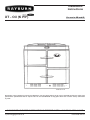
1
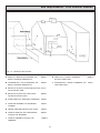
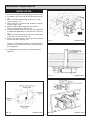
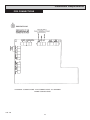
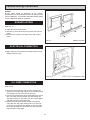
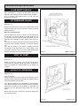
Installation
Instructions
XT - Oil (K P/F)
For use in GB and IE
DESN 514112 B
Remember, when replacing a part on this appliance, use only spare parts that you can be assured conform the safety and
performance specification that we require. Do not use reconditioned or copy parts that have not been clearly authorised
by AGA.
PLEASE READ THESE INSTRUCTIONS BEFORE INSTALLING THIS APPLIANCE
[email protected]
10/13 EINS 514137
Contents
SECTION
CONTENTS
PAGE
CONSUMER PROTECTION
HEALTH & SAFETY
3
3
TECHNICAL DATA
4
SITE REQUIREMENTS
INTRODUCTION
REGULATIONS
LOCATION
OIL PIPE LINE
OIL STORAGE
SINGLE & TWO PIPE SYSTEMS
FLUE SYSTEM
FLUE TERMINAL LOCATIONS
AIR SUPPLY
ELECTRICAL SUPPLY
INSTALLATION
REQUIREMENTS
CLEARANCES
PRELIMINARY INSTALLATION
SITE LOCATION
INSTALLATION
PCB CONNECTIONS
15
15
16
17
18
COMMISSIONING
INSTRUCTIONS
BURNER ACCESS
ELECTRICAL CONNECTION
OIL PUMP CONNECTION
ELECTRICAL CHECK
OVERHEAT SAFETY THERMOSTAT
FLUE SAFETY DEVICE
FIT PRESSURE GAUGE
VENT OIL PUMP
ADJUST OIL PRESSURE
SET COMBUSTION AIR
ANCILLARY CONTROLS CHECK
INSTRUCT THE USER
19
19
19
20
20
21
21
21
21
22
23
23
WIRING DIAGRAM
WIRING DIAGRAM - APPLIANCE
24
SINGLE CHANNEL
PROGRAMMER
SINGLE CHANNEL PROGRAMMER - OPTIONAL
25
2
5
5
5
6
6
7-8
9 - 11
12
13
14
Consumer Protection
As responsible manufacturers we take care to make sure that our products are designed and
constructed to meet the required safety standards when properly installed and used.
IMPORTANT NOTICE: PLEASE READ THE ACCOMPANYING WARRANTY.
Any alteration that is not approved by AGA could invalidate the approval of the appliance,
operation of the warranty and could affect your statutory rights.
Health & Safety
This appliance may contain some of the materials that are indicated It is the Users/Installers
responsibility to ensure that the necessary personal protective clothing is worn when handling
where applicable, the pertinent parts that contain any of the listed materials that could be
interpreted as being injurious to health and safety, see below for information.
Firebricks, Fuel beds, Artificial Fuels
When handling use disposable gloves.
Fire cement
When handling use disposable gloves.
Glues and Sealants
Exercise caution - if these are still in liquid form use face mask and disposable gloves.
Glass Yarn, Mineral Wool, Insulation Pads, Ceramic Fibre
May be harmful if inhaled. May be irritating to skin, eyes, nose and throat. When handling avoid
contact with skin or eyes. Use disposable gloves, face-masks and eye protection. After
handling wash hands and other exposed parts. When disposing of the product, reduce dust
with water spray, ensure that parts are securely wrapped.
Kerosene & Gas Oil fuels (mineral oils)
1. The effect of mineral oils on the skin vary according to the duration of exposure.
2. The lighter fractions also remove the protective grease normally present on the surface of
the skin. This renders the skin dry, liable to crack and more prone to damage caused by cuts
and abrasions.
3. ‘Oil acne’ is recognised by the presence of skin rashes. The arms are most often affected,
but may occur where there is contact with oil or oily clothing.
- Seek medical attention for any rash.
- Avoid skin contact with mineral oil or clothing contaminated with mineral oil.
4. Inhalation of mineral oil vapours must be avoided. Never fire the burner in the open as
unburnt oil vapours are likely to occur.
5. Use a suitable barrier cream which will give protection against mineral oil, lanolin based hand
creams are usually very effective.
6. Never syphon mineral oils by use of the mouth. If accidentally swallowed, call a doctor, do
not induce vomiting.
3
PLEASE NOTE: IT IS ADVISABLE TO
CHECK THE ACTUAL SIZE/WIDTH
OF YOUR APPLIANCE BEFORE
FINALLY FIXING ANY KITCHEN
UNITS SINCE ENAMELLED CAST
IRON CAN VARY IN SIZE.
DESN 514170 B
TECHNICAL DATA
Oil Inlet
R1/4 (1/4” BSP Taper Ext)
Unpacked Weight of Appliance - 350 Kg
Electrical Supply
230V ~ 50Hz 3 amp Fused
Firing Rate - 1.44 l/h
Power Flue to
right or left
54mm St/St Pipe
Flue Terminal Dimensions (mm) -
CO2%
- COOKER
Smoke
0-1
Fuel -
Width - 500 mm
11.0
Height - 210 mm
Depth - 180 mm
Kerosene Class C2 complying with
BS2869 part 2
BURNER
BURNER NOZZLE (US g/h)
0.40 @ 80° H LE DANFOSS
OIL PRESSURE Bar (psi)
7.6 (110)
OIL BURNING RATE cc/m
24
HEAT INPUT kW
14.6
4
Site requirements
INTRODUCTION
The Rayburn is a floor standing
pressure jet oil burner.
LOCATION
cooker, fired by a
Appliance Hearth. The surface temperature of the floor
below the appliance does not exceed 100°C. The
constructional hearth described in current Building
Regulations does not apply. However this appliance must
be installed on a solid floor or base of incombustible
material which is capable of supporting the total weight.
IMPORTANT
l This appliance must only be used with Kerosene
Class C2 Complying with BS2869 Part 2
l A Fire Valve MUST be fitted in the oil supply line.
The location chosen for the appliance must permit the
installation and the provision of a satisfactory flue and an
adequate air supply. The location must also provide
adequate space for servicing and for air circulation around
the appliance. See “Installation of the Appliance”.
l The supplied in line filter MUST be fitted.
REGULATIONS
The space in which the appliance is to be fitted must have
the following minimum dimensions.
THIS APPLIANCE IS A CONTROLLED SERVICE BY
DEFINITION AND REQUIRES EITHER FITMENT
UNDER THE REMIT OF BUILDING CONTROL OR
INSTALLATION BY AN OFTEC REGISTERED 105
TECHNICIAN (CLASSED AS A COMPETENT PERSON)
WHO CAN SELF CERTIFY HIS OWN WORKS.
Between wall or unit and LH side of
- 10mm
appliance top plate
Between wall or unit and RH side of
- 10mm
appliance top plate
SHOULD THE WALL PROJECT BEYOND THE FRONT
OF THE APPLIANCE, IT MUST BE INCREASED TO
50mm (See Fig. 1). To allow door to open enough to
change oven and shelf positions.
Above the raised insulating cover handle - 60mm
This appliance must be commissioned by a competent
engineer such as an OFTEC approved.
The installation of the appliance must be in accordance
with the relevant requirements of the current Building
Regulations BS7671 (formerly IEE Wiring Regulations). It
should also be in accordance with the relevant British
Standard Codes of Practice.
In addition, adequate clearance must be available at the
front of the appliance to enable it to be operated and
serviced. Flue pipes and fittings must not be closer than
10mm to combustible materials and where passing
through a combustible partition such as ceiling or roof,
must be enclosed in a non-combustible sleeve providing
an air space of at least 10mm.
BS 5410 Installation of oil fired appliances for space
heating and hot water purposes Part 1 Boilers of rate
output not exceeding 45kW.
The control of Pollution (Oil) Regulations.
FLUE SAFETY DEVICE
For safety purposes a flue safety device is fitted. This will
only operate in adverse or blocked flue conditions. If the
switch has operated, it should be pushed in, to reset. If
this problem persists it is necessary to determine and
rectify the cause. If it is found necessary to reset more
than once this may indicate a flue blockage.
Spaces around flue pipes passing through walls or floors
should be sealed against the passage of smoke and
flame.
Where the cooker is to stand in a recess or against a wall
which is to be tiled, in no circumstances should the
tiles overlap the cooker top plate.
FIG. 1
5
Site requirements
OIL PIPE LINE
OIL STORAGE
The oil supply connection between the storage tank and
the oil pipe should be run in copper or steel pipe with a
minimum diameter of 10mm. Galvanised pipes and
fittings should not be used. Annealed copper pipe is
preferred with flare type manipulative fittings. Capillary
fittings with soft solder should not be used. Steel pipes
should be joined using taper threads.
The minimum recommended oil tank size is 1400 litres,
Mild Steel Tanks should be to BS. 799 Part 5 and plastic
tanks to OFTEC standard OFS T100.
SEE FIG 2 & 3
HOWEVER in the interests of economical deliveries the
oil tank should be of 3000 litres (600 gallons) capacity.
When positioning the tank, due consideration should be
given to appropriate access for fuel delivery vehicles.
All pipe work and fittings must be completely air tight.
Only oil resistant compounds and PTFE tape should be
used when making joints. Pipe work must be protected
against damage whether fitted above or below ground.
Positioning should comply with the requirements of BS
5410 Pt 1 and OFTEC Technical Book 3.
The size and arrangement of pipe work will depend upon
the distance and height of the oil storage tank in relation
to the oil pump inlet.
The tank should be complete with the following:
1. Sludge Cock (steel tanks)
2. Outlet Valve and filter
3. Contents Indicator
4. Vent Pipe
To prevent entry of water or fitted with return bend.
5. Fill pipe and screw cap. (50mm black pipe)
The oil line from the storage tank to the appliance
must be fitted with a remote acting fire valve
operating at 66ÞC (150ºF) fitted with an appropriate
length of capillary to enable the valve body to be
located externally at the point where the oil line
enters the building. The heat sensing phial of the fire
valve MUST be fitted to the clips, to the left of the
burner.
The use of open lids to fill tanks is not approved.
Steel Tanks - should be mounted on suitable supports. If
of masonary, a damp proof membrane should be
positioned between the tank and its supports to prevent
the steel from rusting when in direct contact with water.
Steel Tanks should slope 20mm for each 1m run from the
oil outlet towards the sludge cock (opposite end).
The 5-10 micron oil filter supplied with the appliance must
be fitted on the oil pipe line and stop valve must be fitted,
as close to the cooker as possible in an accessible
position.
Plastic Oil Tanks - UV Stabilized, plastic tanks are a
modern alternative to steel. These green tanks are
protected against sunlight and do not to stand on piers.
They do however need to be supported over their entire
base. Ideally 50mm smooth faced garden slabs bedded
onto stand or a smooth concrete base.
A flexible pipe connection, approximately 740mm long, is
supplied to fit between the oil supply pipe and the oil
pump for ease of burner removal.
The single tapped outlet makes them more suited to
single pipe gravity feed or where suction lift is necessary
a single pipe feed with deaereator is ideally suitable.
6
Site requirements
DESN 514167 C
Single Pipe oil system
DESN 514169 B
Two Pipe oil system
MAXIMUM
LENGTH
(METRES)
FIG. 2
7
H METRES
0
-3.0
-3.5
-4.0
10mm OD
100
100
88
40
Site requirements
Deaerator Oil System
FIG. 3
DESN 514168 B
ONE & TWO PIPE SYSTEMS
SEE FIG. 4
The cooker as delivered is ready to be used on a one pipe
system. To convert to a two pipe system. (See Fig. 4)
Sections:BURNER ACCESS, steps 1 to 3,
BURNER REMOVAL, steps 1 to 5
PUMP FILTER REPLACEMENT steps 1 & 2
1.
2.
3.
4.
Remove middle screw
Remove horseshoe washer
Replace screw
Re-assemble in reverse order
1-Pipe Operation:
screw with horseshoe washer
2-Pipe Operation:
screw without horseshoe washer
FIG. 4
8
DESN 511449
Site requirements
FLUE SYSTEM
The flue can be to the left or right of the appliance. The
cooker is supplied with the flue pipe to the left, this can be
adjusted to suit the installation.
FLUE DIRECTION - EXIT TO THE LEFT
1. Remove lower back panel (7 screws).
2. Unscrew the two fixing brackets and remove. (See
Fig. 5).
3. Slacken the jubilee clip, fixing flexible pipe to
horizontal pipe (A). (See Fig. 5).
4. If the flue pipe is to be routed as per factory set,
remove bend from manifold and pipe A.
Smear sealant on the end of the manifold, and replace
bend onto the manifold, ensuring it is fully on and
sweeps under the burner chamber.
5. Smear the sealant over the surface of the 28mm
branch on pipe ‘A’. Push the flexible pipe 30-40mm on
to the branch and tighten the jubilee clip.
6. Smear sealant on the first end of pipe ‘A’ and fit to
bend ensuring the branch pipe is slightly above centre.
7. Replace fixing brackets (4 screws).
8. Replace back panel (7 screws) and position cooker.
9
FIG. 5
DESN 512771
FIG. 6
DESN 512770
Site requirements
FLUE DIRECTION - EXIT TO THE RIGHT
Follow previous instructions in FLUE SYSTEM, Steps 1 to
3.
4. Reposition the flexible tube from the oven vent down
the back of the oven.
5. Smear sealant on the end of the manifold and replace
the bend.
6. Smear sealant on the first end of pipe ‘A’ and the
surface of the 28mm branch (towards the bend). Slide
the flexible pipe completely over the branch (pipe
should point towards burner chamber)
7. Push the first end of pipe ‘A’ onto the bend, the
branch should be above the pipe. Tighten the jubilee
clip ensuring the flexible pipe covers all of the branch
pipe.
8. Replace brackets (4 screws).
9. Replace back panel (7 screws).
10
FIG. 7
DESN 512669
FIG. 8
DESN 512779
Site requirements
FLUE SYSTEM
The flue system used on this appliance must be provided
by AGA and must be installed in accordance with the
instructions and standards.
A maximum flue of 5 metres and 5 bends can be used
(including horizontal length on the terminal).
Any upwards vertical runs must be immediate to the
appliance to a maximum of 3 metres. (See Fig. 9)
Downwards vertical runs must be no more than 0.5
metres. (See Fig. 10)
Flue can be positioned to rear or front of appliance via 1
bend. (See Fig. 11).
Horizontal runs must be as level as possible.
FIG. 9
DESN 514115 B
FIG. 10
DESN 514116 B
FIG. 11
DESN 514114
Care must be taken on mounting the terminal and routing
the flue:a. Damage to damp proof course
b. Height above ground
c. General terminal locations (See Fig. 9)
Where the flue passes through combustible material a
minimum of 10mm clearance must be maintained around
the flue pipe and insulation sleeve.
GENERAL REQUIREMENTS
The flue must be adequately supported using the brackets
specified.
The flue pipe must be insulated (supplied).
All joints should be sealed using the sealant provided.
11
Site requirements - Flue terminal location
FIG. 12 - Location of flue terminal
DISTANCES STATED ARE MINIMUM ALLOWABLE REQUIREMENTS
A DIRECTLY BELOW AN OPENING, AIR
BRICK, OPENING WINDOW etc.
600mm
K VERTICALLY FROM A TERMINAL
ON THE SAME WALL
1500mm
B HORIZONTALLY TO AN OPENING, AIR
BRICK, OPENING WINDOW etc.
600mm
L HORIZONTALLY FROM A TERMINAL ON
THE SAME WALL
750mm
C BELOW A GUTTER, EAVES OR BALCONY 75mm
WITH PROTECTION
D BELOW A GUTTER OR A BALCONY
WITHOUT PROTECTION
600mm
E FROM VERTICAL SANITARY PIPEWORK 300mm
F FROM AN INTERNAL OR EXTERNAL
CORNER
300mm
G ABOVE GROUND OR BALCONY LEVEL
300mm
H FROM A SURFACE OR A BOUNDARY
FACING THE TERMINAL
600mm
J FROM A TERMINAL FACING THE
TERMINAL
1200mm
12
Site requirements
AIR SUPPLY
AIR SUPPLY
The appliance can only be installed in a room which
meets the ventilation regulations in force. But, in any
event the room must have a permanent vent of minimum
free air area, see below.
Detailed recommendations for air supply are given in the
Building Regulations, and in BS 5410: Part 1. The
following notes are intended to give general guidance.
MODEL
MIN. AIR REQUIREMENT
XT (K P/F)
61 cm2
1. Combustion and ventilation air supply to oil fired
appliance has to comply with the Building Regulations
and with BS 5410: Part 1. The air supply requirement for
oil fired appliances is 550mm2 per kW of maximum rated
output above 5kW. These requirements are illustrated in
OFTEC Technical Book No.3.
IMPORTANT: THE LOUVRED AIR INTAKE AT THE
BOTTOM FRONT OF THIS APPLIANCE MUST BE
KEPT CLEAR OF ANY OBSTRUCTIONS
2. The combustion air supply to open flued appliances
should normally be provided at high level into a room
where it will not cause discomfort by creating a cold
draught across the floor.
3. If combustion air is supplied through an under floor
duct the grilles at each end should be positioned in the
vertical plane to reduce the risk of blockage. Ducts should
be sized so as to reduce resistance to air flow.
4. The ventilation requirement for kitchens in Part F of the
Building Regulations is for mechanical extract at the rate
of 60 litres per second or 30 litres per second if the fan is
incorporated in a cooker hood.
Background ventilation is also required, either by
producing a constant mechanical extract rate of one air
change per hour or by having ventilation openings of not
less than 4000mm2.
5. Extract fan should be positioned as far away from the
appliance as possible and should have a sufficient
dedicated air supply. To undertake a test the oil fired
appliance should be set in operation and the doors and
windows of the room containing it should be closed. The
extract fan should then be run at its maximum setting. The
oil fired appliance should be observed to operate
satisfactorily both before and after the fan is switched on.
6. It is preferable for the air supply for an extract fan to be
located where it can serve the fan without the air stream
passing close to the oil fired appliance.
7. Oil fired appliances must not draw combustion air from
a garage.
13
Site requirements
ELECTRICAL SUPPLY
Wiring external to the appliance must be installed in
accordance with current National Wiring Regulations and
any local regulations which apply. The appliance is
supplied for 230 Volt ~ 50Hz and a fuse rating of 3 amps.
The method of connection to the mains supply should
facilitate complete electrical isolation of the appliance, by
the use of a fused double pole switch having a contact
separation of at least 3mm serving only the appliance.
The point of connection to the mains should be readily
accessible and adjacent to the appliance. The installation
should be protected by a 30mA Residual Current Circuit
Breaker (RCCB).
The minimum requirement for the power cable is that it
should be a 3 core PVC sheathed flexible cord (85°C min)
at least 0.75mm2 (24 x 0.2mm) to the relevant standard.
WARNING THIS APPLIANCE MUST BE EARTHED
In the event of an electrical fault after installation of the
appliance, preliminary electrical system checks must be
carried out i.e. earth continuity, short circuit, polarity and
resistance to earth.
For wiring instructions see wiring diagrams.
14
Installation requirements
CLEARANCES
The appliance is floor mounted. The space in which the
appliance is to be fitted must have the following minimum
dimensions.
Between wall or unit and LH side of
- 10mm
appliance top plate
Between wall or unit and RH side of
- 10mm
appliance top plate
SHOULD THE WALL PROJECT BEYOND THE FRONT
OF THE APPLIANCE, IT MUST BE INCREASED TO
50mm (See Fig. 1). To allow door to open enough to
change oven and shelf positions.
Above the raised insulating cover handle - 60mm
In addition adequate clearance must be available at the
front of the appliance to enable it to be operated and
serviced.
PRELIMINARY INSTALLATION
The appliance is delivered in a fully assembled condition
with the exception of the following items which are
supplied separately packed and require assembly:The appliance rear distance bracket.
The cooker handrail.
The oil filter and the flexible oil feed pipe.
FIG. 13
FLUE PIPE KIT
Flue pipe kit comprises of:3 x 1 metre length of flue pipe
3 elbows
3 straight couplers
6 support brackets (saddle and clamps)
1 tube ultra-grey sealant
Pack of fastenings
Additional length of flue pipes and fittings are available as
optional extras including a 45Þ bend.
Appliance rear distance bracket: if the rear wall is of
combustible material, there must be an air gap of 25mm
between the wall and the rear of the cooker. Fit the rear
distance brackets as shown in Fig. 13. Whenever possible
it is recommended that the skirting board is removed for
the width of the appliance to enable the rear edge of the
appliance top plate to make contact with the vertical wall
and avoid a rear gap. (Combustible wall excepted).
Where the cooker is to stand in a recess or against a wall
which is to be tiled, IN NO CIRCUMSTANCES SHOULD
THE TILES OVERLAP THE TOP PLATE.
15
DESN 514122
Installation requirements
SITE LOCATION
1. Check that the hearth is level, then remove the
appliance from its transit wooden pallet, and position it
with its back against the wall and in its intended
position for flue connection.
2. Connect and terminate the flue system in accordance
with these instructions.
Connect the relevant services to the appliance:1. Oil (XT KPF)
2. Electric
3. Flue Pipe
4. Fit plinth assembly (See Fig. 14).
5. Fit handrail assembly (See Fig. 15) as follows:
(i)
(ii)
FIG. 14
DESN 514191 A
FIG. 15
DESN 514117 B
Fit mounting brackets to top plate loose.
Fit handrail to brackets. Tigten up screw fixing
brackets to top plate.
NOTE: The handrail ends are tapered to match taper
on top plate. The handrail should only be fitted with
tapered ends going inward toward the top.
(iii) Fit covers onto brackets
NOTE: Tighten grub screw through hole in top door
hinge.
16
Installation Requirements
INSTALLATION
1. Cut out card template from packaging and affix to wall.
2. Cut ø60mm hole in the wall for the flue pipe (See Fig.
16).
3. Drill 4 wall fixing holes through template (1 in each
corner). (See Fig. 16).
4. Drill a minimum of a ø10mm hole through the wall for
terminal supply cable.
5. Remove card template and place flue terminal
assembly onto the hole. (See Fig. 17).
6. The flue termination pipe may require to be shortened
or lengthened depending on wall thickness. (See Fig.
18).
7. Using the large wall fixings permanently fix back plate
to the wall, remove outer cover first.
8. Wire the fan to the supply cable to the terminal block
on the back plate. (See Fig. 19).
FIG. 17
DESN 513356
FIG. 18
DESN 512561
FIG. 19
DESN 513350
Using the 3-core cable provided, run cable back to flue
extractor circuit control at the bottom right hand side
of the appliance.
9. An additional terminal guard is not required for this
appliance.
FIG. 16
DESN 513345
17
Installation Requirements
PCB CONNECTIONS
EXTERNAL CONNECTIONS : FAN CONNECTIONS - AT TERMINAL
MAINS CONNECTIONS
FIG. 20
18
Commissioning Instructions
NOTE: SMOKE/SMELL EMITTED DURING INITIAL
USAGE.
During Initial usage of operation of the cooker,
smoke/smell may be emitted and is normal and not a fault
with the appliance, it is therefore advisable to open doors
and or windows to allow for ventilation.
BURNER ACCESS
SEE FIG. 21
1. Open the burner access door.
2. Remove (5) inner panel securing screws and remove
panel.
3. Remove the (3) plinth securing screws and remove
plinth.
FIG. 21
DESN 514110 B
FIG. 22
DESN 511426
ELECTRICAL CONNECTION
1. Make electrical connections to terminal strip as wiring
diagram (See Fig. 20)
OIL PUMP CONNECTION
SEE FIG 22
1. Bring the sensing phial of the fire valve through the
grommet in the left hand side panel and locate behind
the casting to the left of the burner opening.
2. Connect the flexible hose to the outlet pipe from the oil
filter. DO NOT pass the flexible oil hose through the
side panel casing. If necessary use 10mm O/D copper
tube between the hose and oil filter.
3. Before connecting the flexible oil pipe to the pump
inlet, open the stop valve slowly and run off some of
the oil into a receptacle to establish an air free supply
to the pump. Make the connection onto the pump oil
tight and leave valve open.
19
Commissioning Instructions
ELECTRICAL CHECK
Checks to ensure electrical safety should be carried out
by a competent person.
OVERHEAT SAFETY THERMOSTAT
IMPORTANT NOTE: This appliance is fitted with an
overheat thermostat which has a manual reset button.
If the overheat stat trips, the cooker will not operate,
until the button has been pushed-in (reset). The
engineer needs to follow ‘Fault Finding Guide’ to
establish why it has tripped. (The overheat thermostat
and its sensing phial are located on the controls
chassis rear).
20
Commissioning Instructions
FLUE SAFETY DEVICE
This thermostat is a safety cut-out device which will
operate under adverse wind or a blocked flue condition.
It is a manually reset device which can be reset by
pressing in the centre.
FIT PRESSURE GAUGE
SEE FIG. 23
Remove the bleed screw from the manifold and fit an oil
pressure gauge with R1/8 connection to check the pump
output pressure.
Switch on the Electricity
Set the cooker oven timer to manual, turn the thermostat
to maximum. The burner should run on pre-purge for 7 to
15 seconds, with the ignition spark energised. The oil
solenoid valve should then open allowing the burner to
fire.
Until all the air from the oil pump is flushed out there may
be some flame instability resulting in the burner locking
out.
This will be shown by the burner stopping and the
illumination of the signal light in the reset button of the
control box (see Fig. 24). In this event, wait at least one
minute, then press the re-set button to restart.
FIG. 23
DESN 511427 A
FIG. 24
DESN 511428
VENT OIL PUMP
SEE FIG. 23
Whilst the burner is running, vent air from the pump by
slackening the pressure gauge connection sufficient to
allow air to bleed out. When bubble free oil seeps out
retighten.
ADJUST OIL PRESSURE
SEE FIG. 23
After 15 minutes
Whilst the burner is running check the oil pressure on the
pressure gauge. Wait for 30 seconds after ignition, for the
burner to establish full firing rate.
If the pressure gauge is not indicating the correct reading
then adjust the pressure by turning the pressure regulator
clockwise to increase or anti-clockwise to decrease the
pressure until the pressure gauge reads 7.6 bar (110
lb/in2).
Switch off the burner, remove the pressure gauge and
refit the bleed screw.
21
Commissioning Instructions
SET COMBUSTION AIR
SEE FIG.25 & 26
The air control of the burner is factory pre-set, however
small adjustments may be necessary to suit the site
conditions.
IMPORTANT: Ensure that the bottom louvred plinth is in
place during combustion setting procedures and the outer
door is closed.
Turn burner on. Check flue fan is running.
After 15 minutes lift up the R.H. insulating cover and
remove the counter sunk screw and insert the sensing
end of a portable indicator to check the CO2 (Carbon
Dioxide) level. Adjust the burner air intake until a reading
of 11.0 CO2 is recorded on the indicator.
Check Smoke
Remove the CO2 sampling tube and using the same hole
for flue sampling insert the sensing end of a Baccarach
Smoke Pump and check that the smoke does not exceed
0 - 1 on the scale. Replace the countersunk screw.
NOTE: Ensure that the Hotplate is fitted correctly as this
forms part of the cooker combustion circuit.
22
FIG. 25
DESN 511429 A
FIG. 26
DESN 514111
Commissioning Instructions
ANCILLARY CONTROLS CHECK
INSTRUCT THE USER
Before leaving the site, check that the operation of cooker
timer and thermostat are capable of controlling the burner
correctly. Check the operation of burner control box.
1. Advise the User that, for continued efficient and safe
operation of the appliance, it is important that adequate
servicing is carried out at regular 12 monthly intervals.
In the event of a flame failure the control box should cut
off the oil supply by closing the solenoid valve. The reset
buttons will then be illuminated.
2. Hand the Operating Instructions to the User and
demonstrate the correct operation of the appliance and
system controls.
WAIT 1 MINUTE BEFORE RESETTING THE CONTROL
BOX.
3. Leave the Installation and Servicing Instructions with
the User.
23
Wiring Diagram
WIRING DIAGRAM - APPLIANCE
FIG. 27
24
Single Channel Programmer
USING A SINGLE CHANNEL OPTIONAL PROGRAMMER IN CONJUNCTION
WITH THE RAYBURN 400K PX (P/F) ONLY
1. Always use the same isolating switch for both the cooker and programmer.
Ideally: always use the supply connections on the appliance.
2. Before carrying out any maintenance work on either the programmer or the cooker ensure the supply is isolated.
PROGRAMMER WIRING
ALL WIRING TO THE IEE REGULATION BY A QUALIFIED ENGINEER
USERS INSTRUCTIONS GUIDE PROGRAMMER AND TIMER COMBINATION
1. The “Time of Day” alarm and ‘Minute Minder’ functions can all be used without effecting the external
programmer timings.
2. When using Auto Cook Function on the internal timer ensure the external wall programmer is in the
continuous ‘ON’ mode.
3. When using the external wall programmer: ensure it is set correctly i.e. timed. The internal cooker timer
should be in Manual Mode.
4. Please read in conjunction with the instructions supplied with your external programmer.
25
26
27
For further advice or information contact
your local distributor/stockist
With AGA Rangemaster’s policy of continuous
product improvement, the Company reserves the
right to change specifications and make
modifications to the appliance described at any
time.
Manufactured by
AGA Rangemaster
Station Road
Ketley Telford
Shropshire TF1 5AQ
England
www.rayburn-web.co.uk
www.agacookshop.co.uk
28