1
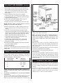
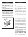
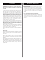
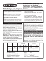
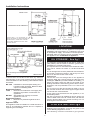
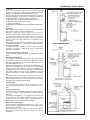
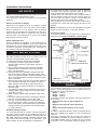
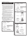
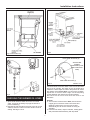
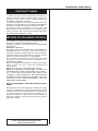
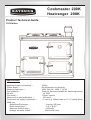
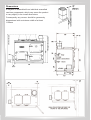
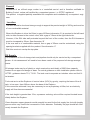
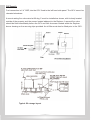
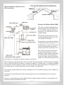
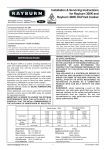
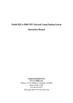
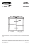
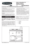
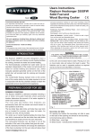
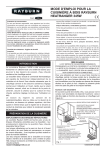
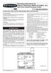
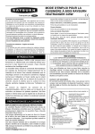
WARNING
This information is a copy of an original
archive, therefore Aga cannot be held
responsible for its continued accuracy.
Users Instructions for Rayburn
Cookmaster 200K and Rayburn
Better than you ever imagined Cookmaster 208K Oil Fired Cooker
applicable, the pertinent parts that contain any of the listed
materials that could be interpreted as being injurious to health and
safety, see below for information.
Consumer Protection Act 1987
As responsible manufacturers we take to make sure that our
products are designed and constructed to meet the required safety
standards when properly installed and used.
Firebricks, Fuel beds, Artificial Fuels - when handling use
disposable gloves.
IMPORTANT NOTICE: PLEASE READ THE
Fire Cement - when handling use disposable gloves.
ACCOMPANYING WARRANTY. Any alteration that is not
approved by Aga, could invalidate the approval of the appliance,
operation of the warranty and could also affect your statutory
rights.
Glues and Sealants - exercise caution - if these are still in liquid
form use face mask and disposable gloves.
Glass Yarn, Mineral Wool, Insulation Pads, Ceramic Fibre,
Kerosene Oil - may be harmful if inhaled, may be irritating to skin,
eyes, nose and throat. When handling avoid inhaling and contact
with skin or eyes. Use disposable gloves, face-masks and eye
protection. After handling wash hands and other exposed parts.
When disposing of the product, reduce dust with water spray,
ensure that parts are securely wrapped.
Control of Substances - Health and Safety
Important
This appliance may contain some of the materials that are
indicated.
It is the Users/Installers responsibility to ensure that the necessary
personal protective clothing is worn when handling, where
knob and its setting.
NOTE: FOR LONG SHUT-DOWN PERIODS, CLOSE
ALL OIL VALVES BETWEEN THE OIL TANK AND THE
APPLIANCE.
INTRODUCTION
The cooking performance features of the popular and
proven solid fuel Rayburn Cookers have been
preserved and integrated into the Rayburn Cookmaster
200K and Rayburn Cookmaster Plus 208K burning 28
Second Kerosene to BS: 2869: 1988 Class C2.
WARNING: OIL BURNER: NEVER ATTEMPT TO
RELIGHT A HOT BURNER - DO NOT TURN OIL ON
UNTIL BURNER IS COOL.
NOTE: SMOKE/SMELL EMITTED DURING INITIAL
USAGE.
Some parts of the cooker have been coated with a light
covering of protective oil. During initial operation of the
cooker, this may cause smoke/smell to be emitted and
is normal and not a fault with the appliance, it is
therefore advisable to open doors and or windows to
allow for ventilation. Lift the lids to prevent staining the
linings.
IM
P
O
R
TA
N
T
co he
nt co
at inu ok
lo ou er
th w f sly bur
re e ir a n
co co e r li er
m o a gh i
is m ker te w t c s in
re en b h on te
qu de ur en d nd
i
co ire d u ner id tion ed
l
un ok d o nle OF ing at to r
fo at er i r w ss F i . T all un
r s ten s he se s ur ti in
da ev de left n t rvi NO nin me a
he ci T g s,
ys era d
ng
. l
T
The Rayburn Cookmaster 208K provides domestic hot
water and cooking facilities, whereas the Rayburn 200K
provides cooking facilities only, which consists of a heat
graduated hotplate, main oven and warming oven. The
circulator oil burner is controlled by a manually operated
oil valve control knob. The burner should always be
continuously burning at low fire rate when not required
for cooking. When cooking is required, the burner
operates at a high fire rate by adjustment of the control
[email protected]
1
07/06 EOPI 511030
TO LIGHT THE BURNER -
See Fig.1
1. Remove the oil control valve cover, then depress the
trip lever D on the front of the oil control valve and turn
the cooker oil control valve knob C to No. 6 setting.
Allow 15 minutes for oil to enter and settle in cooker
burner base.
2. Open outer burner door adjacent to the bottom
warming oven door, remove/lift out inner burner door.
3. Lift hinged lighting cover on the front of the burner shell
and expose the lighting port.
4. Insert a taper through the lighting port and light the
front wick, then close the lighting cover.
5. Replace inner burner door and close outer burner door.
NOTE: ENSURE INNER COOKER BURNER DOOR IS
CORRECTLY LOCATED AND SEALED.
6. Return control knob C to its No. 1 setting for about 20
minutes, until the burner is hot, then re-set to No. 6 for
cooking.
7. The cooker burner will gradually increase its oil rate,
and raise the temperature of the oven, taking about 21/2
hours from cold to attain an oven temperature of 200°C
(400°F), leaving the cooker control knob C at its No. 6
setting. Re-set the cooker control knob C to an
intermediate setting and the oven temperature will
maintain the desired temperature.
8. Set the cooker control knob C to No. 1 which is the
minimum setting when cooking is not required and
idling rate is needed.
9. Ensure both hotplate insulating covers are closed down
to conserve heat in hotplate.
Fig.1.
required temperature will be maintained by lowering the
setting of the cooker control knob
HINT: THE SOLID PLAIN SHELF CAN BE USED AS A
HEAT DEFLECTOR, (AS WELL AS A BAKING SHEET).
SLIDE ONTO RUNNERS TOWARDS THE TOP OF THE
OVEN WHICH REDUCES THE HEAT UNDER THE
SHELF.
The Hotplate
When the main oven is in use the hotplate will be hot
enough for normal needs. The hotplate area above the
main oven is used for simmering with the opposite end
being the hottest.
At other times, increase the setting of the control knob C to
increase the temperature of the hotplate.
Pans and kettles must have flat machined bases.
To Turn Off Oil Burner
Turn the oil control valve knob C anti-clockwise from No.6
setting to OFF, and lift the trip lever D on the front of the oil
control valve.
OVEN CONTROL KNOB SETTINGS
Warming Oven
This is at a low temperature suitable for warming serving
plates and dishes. Although not intended as a cooking
oven, its temperature does vary with temperature of the
main oven. As a guide, it is around a third the temperature
of the main oven.
The oil valve control knob C is marked 1 to 6, which
provides main oven temperatures with setting 6 being the
highest temperature - see chart below.
Cooker Control
Knob Setting
Main Oven
Temperature
1 IDLING
2
3
4
5
6
150° - 170°C
170° - 190°C
210° - 230°C
250° - 270°C
HIGH
HIGH
DOMESTIC HOT WATER
The supply of domestic hot water to the cylinder is
automatic and is at its maximum when the control knob C
is on No. 6 setting, reducing as the control knob setting is
reduced.
The amount of hot water is increased if a considerable
amount of cooking is performed. If more hot water is
required overnight, set the control knob C to a higher
setting than No. 1, which is normally sufficient.
NOTE: NON-BOILER MODELS MAY OPERATE AT
HIGHER TEMPERATURES THAN THOSE QUOTED
ABOVE .
To Heat the Top Main Oven and Increase Hotplate
Temperature
Turn the control knob C to the required setting which will
take up to 90 minutes to attain from idling temperatures.
When the top main oven temperature is reached, the
2
OVERNIGHT
COOKING HINTS
Turn the control knob C to No.1 which give the lowest
burning rate and will maintain an oven temperature of
about 150°C-170°C. At a higher setting, the oil
consumption will be higher, but the main oven, hotplate
and domestic hot water will be hotter.
Turn the control knob C to No.6 setting in the morning to
increase the hotplate temperature and minimise the time to
boil a kettle of water.
The recommendations for the best use of the appliance
are guidelines only, and the respective setting of the
cooker control knob which suits your requirements will be
apparent with experience.
The oven is indirectly heated from outside by hot gases
from the heat source so that no flame or elements within
the oven means full use can be made of the whole cooking
space.
WHEN THE COOKER IS NOT IN USE
One of the many benefits of the cast iron main oven is that
the floor of the oven is hotter than that of a conventional
cooker. No need to bake pastry quiche cases “blind”, just
place the flan dish on the oven floor for ‘soggy-free’ pastry.
When the oven is hot, the floor of the oven can be used for
shallow frying (a cast iron dish is recommended) with the
added advantages that fat splashes are carbonsied so
cleaning is minimised and frying smells are taken away
through the flue.
The main oven is slightly hotter towards the top than the
bottom. At a low idling heat the main oven can be used for
long slow cooking such as casseroles, stock, soup,
ratatouille, curries, meringues, creme caramels, rice
puddings etc., all of which benefit from the gentle slow
heat, and as the oven is vented into the flue, cooking
smells disappear to the outside.
During periods of the day when the cooker is not required,
the control knob C should be set at No. 1 to give the lowest
burning rate which will in most cases give sufficient heat to
the hotplate and hot water. Use the setting that meets your
needs.
Frost Precautions
In the event of the boiler bring unheated for long periods
during very cold weather, the advice of your installer
should be obtained.
For perfect baking results, turn food during cooking.
The top of a hot oven is where grilling takes place, use the
meat tin with a grill rack so that the fat can drip into the
tray.
The thermodial temperature gauge, on the main oven door
is a guide to the internal oven temperature. Remember
though, on opening the door the temperature will appear to
drop, do not worry, close the door and after a few minutes
the true oven temperature can be read again. Heat is not
lost as quickly from a cast iron oven as a pressed metal
box type so you can peep at the cake to see how it is
cooking without it sinking.
As you have probably realised, the meat tin supplied with
your Rayburn fits the oven size, hanging directly from the
runners, so leaving the grid shelves free for other dishes.
The oven grid shelves are designed to be non-tilt and
should be fitted with the upstand to the top and at the
back, so when pulled forward the shelf cannot come right
out. (See Fig. 2)
The solid plain shelf, as mentioned before, can be used as
a baking sheet or as a heat deflector. If the oven is too hot
or food already in the oven is beginning to over-brown,
slide the solid plain shelf, above the food. To be effective
this shelf should be stored out of the oven so it is used
from cold.
Fig. 2
NOTE: SEE COOK BOOK FOR RECIPES.
DO NOT USE ABRASIVE PADS OR OVEN CLEANERS.
NOTE: IT IS NOT ADVISABLE TO PUT VERY WET
CLOTHES ON THE HAND RAIL, AS THIS MAY CRAZE
THE ENAMEL.
IMPORTANT - USE 28 SEC KEROSENE FUEL ONLY.
3
CLEANING
BI-ANNUAL SERVICING
REMEMBER: BE CAREFUL OF THE HOT APPLIANCE.
Bi-annual Servicing
With normal use a cooker annual flueway clean and burner
maintenance should be carried out at 6 monthly intervals.
The cooker oil valve control knob should be turned OFF by
the User the night before the day of the servicing so that
the appliance will have cooled down by the following
morning.
DO NOT USE A STEAM CLEANER TO CLEAN THIS
COOKER.
To keep the vitreous enamelled surface bright and clean,
wipe over daily with a soapy damp cloth, followed by a
clean dry duster. If milk, fruit juice or anything containing
acid is spilt on the top plate or down the cooker, be sure to
wipe it immediately or the vitreous enamel may be
permanently discoloured. Keep a damp cloth handy, while
cooking to wipe up spills as they occur, so they do not
harden and become more difficult to remove later. If spills
do become baked on a cream cleanser can be used. For
stubborn deposits a soap impregnated pad can be
carefully used on the vitreous enamel.
In the main oven, spills and fat splashes are carbonised at
high temperatures; occasionally brush out with a stiff
brush. The oven door can be removed for cleaning - do
not immerse in water, and shelves can be soaked and
cleaned with a cream cleanser.
Both insulating covers should be raised and allowed to
cool before cleaning with a soapy damp cloth. Use a wire
brush to keep the cast iron hotplate clean.
General cleaning is best carried out when the Rayburn is
cool.
A HOT APPLIANCE CANNOT BE SERVICED.
Your Rayburn stockist will provide advice on obtaining the
nearest selected Servicing Engineer, where we
recommend you contract out the periodical servicing of the
appliance.
IMPORTANT:
Aga recommend Vitreous Enamel Association approved
cleaners for cleaning the vitreous enamelled surfaces of
this product.
But they are unsuitable for use on chrome and stainless
steel components, including the hand-rails and their
brackets.
The insulating covers should be cleaned regularly with a
NON-ABRASIVE mild detergent, applied with a soft
(coarse free) cloth and lightly polished up afterwards with a
soft (coarse free) duster or tissue, to bring it back to its
original lustre.
4
5
6
7
For further advice or information contact your
local distributor/stockist
With Aga’s policy of continuous product
improvement, the Company reserves the right to
change specifications and make modifications to
the appliance described at any time.
Manufactured by
Aga
Station Road
Ketley Telford
Shropshire TF1 5AQ
England
www.aga-web.co.uk
www.agacookshop.co.uk
www.agalinks.com
8
Better than you ever imagined
Installation and Servicing
Instructions for Rayburn
Cookmaster 200K and Rayburn
Cookmaster Plus 208K Oil-Fired
Cooker
Consumer Protection Act 1987
materials that could be interpreted as being injurious to health and
safety, see below for information.
As responsible manufacturers we take care to make sure that our
products are designed and constructed to meet the required safety
standards when properly installed and used.
Firebricks, Fuel beds, Artificial Fuels - when handling use
disposable gloves.
Fire Cement - when handling use disposable gloves.
IMPORTANT NOTICE: PLEASE READ THE ACCOMPANYING
WARRANTY. Any alteration that is not approved by Aga, could invalidate
the approval of the appliance, operation of the warranty and could also
affect your statutory rights.
Glues and Sealants - exercise caution - if these are still in liquid
form use face mask and disposable gloves.
Glass Yarn, Mineral Wool, Insulation Pads, Ceramic Fibre,
Kerosene/Gas Oil - may be harmful if inhaled, may be irritating to
skin, eyes, nose and throat. When handling avoid inhaling and
contact with skin or eyes. Use disposable gloves, face-masks and
eye protection. After handling wash hands and other exposed
parts. When disposing of the product, reduce dust with water
spray, ensure that parts are securely wrapped.
Control of Substances - Health and Safety
Important
This appliance may contain some of the materials that are
indicated. It is the Users/Installers responsibility to ensure that the
necessary personal protective clothing is worn when handling,
where applicable, the pertinent parts that contain any of the listed
APPLIANCE TO THIS INSTALLING/SERVICING
ENGINEER.
REMEMBER, when replacing parts on this appliance,
use only spare parts that you can be assured conform
to the safety and performance specification that we
require. Do not use reconditioned or copy parts that
have not been clearly authorised by AGA.
INTRODUCTION
The Rayburn Cookmaster Plus 208K is a cooker
providing domestic hot water and cooking facilities. It is
available with a vertical flue outlet only, with the oil
burner operating on natural draught.
The boiler is designed for use in an open vented water
system only, with gravity D.H.W. primaries.
Alternatively, the Rayburn Cookmaster 200K is a nonboiler model. However, with this model the idling
temperature may be higher.
These appliances must only be used with Commercial
Grade C2 Kerosene.
This appliance must be commissioned by a competent
engineer, such as OFTEC approved.
INSTALLATION INSTRUCTIONS
THIS APPLIANCE IS A CONTROLLED SERVICE BY
DEFINITION AND REQUIRES EITHER FITMENT
UNDER THE REMIT OF BUILDING CONTROL OR
INSTALLATION BY AN OFTEC REGISTERED 105
TECHNICIAN (CLASSED AS A COMPETENT
PERSON) WHO CAN SELF CERTIFY HIS OWN
WORKS.
IMPORTANT: IN ORDER TO ACHIEVE THE OPTIMUM
PERFORMANCE FROM THIS APPLIANCE, IT IS
ESSENTIAL THAT THE INITIAL COMMISSIONING OF
THE APPLIANCE IS UNDERTAKEN BY SELECTED
TRAINED INSTALLING SERVICE ENGINEERS.
YOUR RAYBURN STOCKIST WILL PROVIDE ADVICE
ON THE LOCATION OF THE NEAREST INSTALLING
ENGINEER. WE ALSO RECOMMEND YOU CONTRACT
OUT THE PERIODIC SERVICING OF THE
The installation of the appliance must be in accordance
with the relevant requirements of the current Building
Regulations, current I.E.E. Wiring Regulations and the
byelaws of the local Water Undertaking.
Boiler Model
kW
Btu/h
kW
Btu/h
Cooker
LOW
2.43
8,312
0.73
3,000
Cooker
HIGH
7.42
25,321
2.34
8,000
cc/minute
4.0
13.0
Heat Input
Heat Output
Water
Oil Input
Rate
Boiler Water Connections
Flow (one)
Rp 1 (1in BSP Int)
Return (one)
Rp1 (1in BSP Int)
Both connections are located towards the
rear edge of the appliance L.H. side panel.
Oil Valve Inlet
Rp1¼4 (1¼4 in BSP Int)
[email protected]
Non-Boiler
Model
Cooker
Cooker
LOW
HIGH
2.16
5.48
7,386
18,700
3.5
8.5
Weight of
305Kg
Appliance
Appliance Overall Height: 995mm
Dimensions
Width: 940mm
Depth: 575mm
FUEL - COMMERCIAL GRADE C2 KEROSENE
1
02/06 EINS 511029
Installation Instructions
DESN 511031
DIMENSIONS IN MILLIMETRES
PLEASE NOTE: IT IS ADVISABLE TO
CHECK THE WIDTH OF YOUR APPLIANCE
BEFORE FINALLY FIXING ANY KITCHEN
UNITS SINCE ENAMELLED CAST IRON
CAN VARY IN SIZE
LOCATION
The location chosen for the appliance must permit
installation and the provision of a satisfactory flue and
an adequate air supply. The location must also provide
adequate space for servicing and air circulation around
the appliance. See “Installation of Appliance”.
OIL STORAGE - See fig.1
Fig.1 Oil Storage tank and pipeline
details
The minimum recommended oil tank size is 1400 litres
(300 gallons) and the Codes of Practice governing its
installation are covered by BS. 5410.
The requirements for mild steel tanks should be to BS.
799, Part 5. Plastic Oil Tanks to, OFTEC Standard
T100.
The oil storage tank must be positioned with the bottom
of the tank not less than 630mm, and the top not more
than 3.2m above the base of the cooker.
Oil Pipe Line
The oil line from the storage tank to the appliance
should be fitted with a remote acting fire valve (such as
Teddington KBB-66ºC) located outside the building, or
where the supply enters the wall on the inside of the
building and with the heat sensing phial of the fire valve,
located as near as practicable on the L.H. side of the
cooker.
A 5-10 micron oil filter should also be fitted in the oil
line, and the minimum size of the copper oil pipe should
not be less than 10mm diameter.
A stop valve must be fitted near the appliance, in an
accessible position.
We also recommend an additional remote acting fire
valve be fitted close to the oil control valve, with its heat
sensing phial located in the burner housing, but not
touching, the inner burner door.
DESN 510210
It should be in accordance also with any relevant
requirements of the Local Authority and the relevant
recommendations of the following current British Codes
of Practice:
BS. 5410
Installation of oil fired space heating and
hot water supply purposes. Boilers of rated
output not exceeding 44kW.
Building Regulations
J1/4/5
Provision for introduction of air supply and
discharge of products of combustion for
appliances.
BS.4543 Specification for chimney for oil-fired
appliances. Part 1-3.
Building Regulations
J1/4/5
Provision for protection against fire and
heat.
Appliance Hearth
This appliance must be installed on a solid level floor or
base of incombustible material which is capable of
supporting the total weight.
FLUE SYSTEM - See Fig.2
Detailed recommendations for fluing are given in the
current Building Regulations J1/4/5.
The following notes are intended to give general
2
Installation Instructions
guidance:The cross sectional area of the flue serving the
appliance must not be less than the area of the flue
outlet of the appliance and be at least 4.5m high.
The flue pipe to be used must not be less than 102mm
internal diameter. Flue pipes and fittings should be
constructed from one of the following materials:
a) Mild Steel with a wall thickness of 3mm minimum.
b) Stainless Steel to BS. 1449. Part 2
c) Cast Iron to BS. 41.
d) Mild Steel, acid resistant vitreous enamel lined to BS.1344.
Part 2.
Chimneys
Chimneys should be built of masonry or be assembled
from factory-made insulated components.
Masonry chimneys may be built of any masonry
material, with a lining, of if flue blocks, without a lining.
The chimney lining should be 125mm minimum
diameter and be formed of moisture and acid resistant
liners to BS.1181 with rebated or socketed joints
uppermost.
Alternatively, linings may be imperforate clay flue pipes
as described in BS.65 or flue blocks to BS.1289 and
installed to BS.6461.
A 125mm minimum diameter factory-made, insulated
chimney, complying to BS 4543 may be fitted and
installed to BS.7566.
Use of older existing chimneys
Older chimneys must be swept and a suitable flexi liner
fitted.
Chimney Terminations
All chimneys should terminate above the roof level in
accordance with current Building Regulations and
statutory requirements as outlined in BS.6461 Part 1
and BS.7566 Parts 1 to 4.
However well-designed, constructed and positioned, the
satisfactory performance of a flue can be adversely
affected by the down-draught caused by adjacent tall
buildings and trees or even nearby hills. These deflect
the wind creating a zone of high pressure over the
terminal causing it to blow directly down the chimney
flue.
A suitable anti-downdraught terminal such as the
Marcone will usually effectively combat low pressure
down-blow but no known cowl is likely to prevent downdraught due to a high pressure zone.
Flue Draught
For correct performance of the appliance, it is
recommended that the flue pull be a minimum of 1mm
H2O.
Chimney Cleaning
Ensure there are accessible airtight flue cleaning doors
in order to obtain cleaning access to the complete
chimney.
Providing the appliance is operating correctly, an
annual chimney flue clean will suffice, but if in doubt,
arrange for a half yearly clean, preferably at the
beginning/end of the central heating season.
High Chimney Draughts
A well sealed, tall exposed chimney on a hill, is an
instance where generated draughts could be excessive
and must be controlled.
Should this occur, a flue stabiliser must be fitted either
in the flue pipe or chimney, but in the same room as the
appliance.
Fig.2 Flue Layouts
3
Installation Instructions
The water draw-off pipes to the taps must be dead leg
connection from the vent expansion pipe. A drain tap
must be fitted at the lowest point of the system.
A towel rail of not more than 0.5mm2 heating surface
may be heated providing the flow and return pipes are
not more than 5m each in length, and provided the
cylinder and pipes to the cylinder are insulated.
If the cylinder is very close to the cooker, a towel rail is
advisable as a heat leak and lagging should not be
applied.
AIR SUPPLY
Detailed recommendations for air supply are given in
the current Building Regulations J1/4/5.
The following notes are intended to give general
guidance:Kitchen or Internal Air Supply
Wherever a flue appliance is to be installed, it must
have a permanent air vent. This vent must be either
direct to outside air or to an adjacent room or internal
space which must itself have a permanent air vent of at
least the same size direct to outside air. The minimum
effective area of the permanent air vent in the outside
wall must be 30.5cm2 (4.75in2).
NOTE: The appliance must not be operated if the water
system is out of operation, or has been drained.
Corrosion Inhibitor
A corrosion inhibitor can be used when installing this
appliance to an Indirect Hot Water Cylinder Only.
Effect of Extractor Fan
Avoid if possible the installation of an extractor fan in
the same room as the appliance or the room where the
permanent air vent is located. Additional air inlets must
be fitted to introduce compensating air, equivalent to
the capacity of the fan when fitted.
HOT WATER SYSTEM
Hot water systems should be in accordance with the
relevant recommendations given in BS. 6700.
The following notes are of particular importance.
1. In domestic hot water systems the hot water
storage vessel must be of the indirect cylinder of
calorific type.
2. The hot water storage vessel should be insulated,
preferably with not less than 75mm thick mineral
fibre, or its equivalent.
3. Pipework should be insulated to help prevent heat
loss and possible freezing, particularly where pipes
are run through roof spaces. Cisterns situated in area
which may be exposed to freezing conditions should
also be insulated.
4. Draining taps must be located in accessible positions
which permit the draining of the appliance and hot
water storage vessel. Draining taps should be at
least 1/2in BSP nominal size and be in accordance
with BS. 2879.
5. The appliance boiler section should be connected to
a cistern water supply, subject to a maximum head
of 18.25m (1.8 bar).
6. Water carrying copper tubes should be to BS. 2871,
Part 1.
7. Hot water systems should be in accordance with the
relevant recommendations given in BS. 6700.
8. The use of horizontal pipe runs should be avoided
wherever possible in order to prevent the collection
of air in the system. If horizontal runs are unavoided
the pipes should rise upwards in the direction away
from the appliance.
Fig.3 Typical Gravity System
INSTALLATION OF APPLIANCE GENERAL
The combined appliance is floor-mounted and the
space in which the appliance is to be fitted must have
the following minimum dimensions:Width: 1145mm
Depth: 1575mm
Height: 1320mm
This space includes the following minimum clearances
for servicing:Between wall and L.H. side of appliance
300mm
Between wall and R.H. side of appliance
Zero
Above the raised insulating cover handle
75mm
In addition, adequate clearance must be available at the
front of the appliance to enable it to be operated and
serviced.
Flue pipes and fitting must not be closer than 25mm to
combustible materials and where passing through a
combustible partition such as a ceiling or roof, must be
enclosed in non-combustible sleeve providing an air
Hot Water Storage Vessel
It is recommended that an indirect 140 litre (30 gallon)
hot water storage cylinder of the double feed type e.g.
(Manufactured by Albion Cylinders) complying with the
BS. 1566, should be insulated, preferably with not less
than 75mm thick mineral fibre or its equivalent, and
fixed vertically as near as possible to the appliance.
4
Installation Instructions
space of at least 25mm.
Spaces around the flue pipes passing through walls or
floors should be sealed against the passage of smoke
and flame.
PRELIMINARY INSTALLATION
The appliance is delivered in a fully assembled
condition with the exception of the following items which
are supplied separately packed and require assembly.
1. Complete, but dis-assembled oil burner with spare
set of wicks.
2. Oil Constant Level Valve and Support Bracket.
3. Flue Outlet Assembly.
4. Handrail Tube.
5. Appliance rear distance bracket - For use when the
appliance is installed near a rear wall or combustible
material - See Fig. 4.
6. Boiler sealing cement.
7. 8mm dia copper oil feed tube.
8. Boiler pipe Collars - Boiler Model Only.
Wherever possible, it is recommended that skirting
board is removed for the width of the appliance to
enable the rear edge of the appliance top plate to make
contact with the vertical wall, and avoid a rear air gap.
(Combustible walls excepted).
Where the cooker is to stand in a recess or against a
wall which is to be tiled, in no circumstances should
the tiles overlap the cooker top plate.
Fig.3a
DESN 510454 A
8. Place and locate the cast-iron baffle and stainless
steel baffle assembly as per Fig.7 through the
hotplate aperture. Replace the hotplate with the fins
over the oil burner position.
WATER CONNECTIONS
Remove the sheet metal panel in the area of boiler
pipes on the LH side of appliance to expose the two
Rp1 (1in BSP int) flow and return tappings in the boiler.
Pipe connections should be made with Rp1 (1in. BSP
ext) x 28mm dia copper compression fittings or steel
pipe nipples. Replace panel and fit pipe collars.
Gravity Domestic Hot Water
The 28mm O.D. primary flow pipe must rise
continuously from the boiler section to the cylinder to
ensure good gravity circulation and extended to provide
an open vent.
The 28mm O.D. primary flow and return pipes must not
exceed 10m in length. Pipe runs in excess of 5m must
be lagged.
Seal the boiler body to the combustion chamber
with fire cement provided, or non-boiler models
remake any distributed seals on firebrick assembly.
The handrail brackets are held on the front ends of the
cooker top-plate casting. Remove the travel nuts and
replace with the handrail brackets ensuring the fibre
protecting washers are in position. Insert the handrail
with fitted endcaps into the brackets, positioning them
correctly, tighten the locating bolts (Fig. 3a).
SITE LOCATION
1. Check that the hearth is level, then move the
appliance from its transit wooden pallet, and position
it with its back against the wall and in its intended
position, for flue connection.
NOTE: IF THE REAR WALL IS OF COMBUSTIBLE
MATERIAL, THERE MUST BE AN AIR GAP OF
25mm BETWEEN THE WALL AND REAR AS
SHOWN IN FIG. 4.
2. Locate and secure flue outlet spigot to top plate with
sampling hole at front. Place horizontal baffle on
spigot and locate flue outlet hood on baffle
supported by internal screws. See Fig. 5.
3. Locate and fit flue pipe into flue socket, sealing joint
with fire cement.
4. Connect and terminate the flue system in
accordance with standard practice.
5. Coat the male thread of the oil burner pipe assembly
elbow with oil resistant compound and screw into
the burner base, check position of elbow. See Fig. 6.
Visually confirm that the oil burner pipe is level or
slopes upwards to the oil entry in the burner base, to
avoid air locking.
6. Fit oil burner base to support plate and secure with 3
bolts.
7. Lift up insulating covers and remove hotplates.
(Boiler Model Only).
OIL CONTROL VALVE INSTALLATION
1. Fit and lightly secure oil control valve support bracket
to cooker LH side panel. See Fig. 8.
Using a spirit level, check that the horizontal face of
the support bracket is level in all directions, then
tighten and secure bracket fixing screws.
2. Mount oil control valve on support bracket and adjust
its height (via locknuts) so that the ‘OIL LINE’ mark
on the LH side of the oil control valve body,
measures a vertical height of 256mm from the valve
body ’mark’ to the base plate level.
NOTE: IF THE APPLIANCE IS MOUNTED ON A
PLINTH, ADD THE HEIGHT OF THE PLINTH TO THE
DIMENSION GIVEN. CHECK USING A SPIRIT LEVEL,
THAT THE TOP OF THE VALVE IS LEVEL IN ALL
DIRECTIONS.
5
Installation Instructions
BURNER INSTALLATION
1. Open outer burner door and lift/remove inner burner
door.
2. Withdraw oil burner base assembly and place on a
work surface. Locate the perforated shell assemblies
onto burner base (lighting port at burner front), and
check that the shell assemblies seat correctly (near
airtight) and that the top horizontal baffle fits on top
of the shells. Remove the shells, and check that the
vapourising chamber plug fits snugly into the base,
and that the vapourising wicks fit into the burner
base grooves.
3. Transfer the oil burner base assembly into
combustion chamber with centre support at the rear
end and the two front support screws forward in the
combustion chamber.
Adjust the front support levelling screws of the
burner assembly until it is level in all directions, then
tighten the locknuts on the levelling screws. Use a
cross spirit level to ensure burner is level in all
directions.
NOTE: THE BURNER BASE MUST BE LEVEL.
4. Insert the copper oil feed pipe through the side of
the cooker with the front end turned upward for
connection to the burner base front elbow.
The opposite end of the pipe should be connected to
the elbow on the outlet of the oil control valve.
NOTE: KINKING OF THE OIL FEED PIPE MUST BE
AVOIDED OTHERWISE AIRLOCKING WILL OCCUR.
ALWAYS RUN THE PIPE TO A LOW LEVEL POINT,
THEN GRADUALLY PROVIDE A CONTINUAL
UPWARD SLOPE TO THE BURNER.
5. Connect oil supply tank feed pipe to inlet of oil
control valve open all oil valves to allow oil into
control valve. It may be necessary to purge the oil
line to prevent air locking.
Fig.5
Fig.6 8 ” Burner assembly - 208K Boiler Model DESN 511029
TOP PLATE
SET OF
SHELLS
DEEP WELL
BURNER BASE LID
Fig.4 Clearance Between Cooker and Combustion Wall
BURNER WICKS
BURNER BASE
CARBON LEG
ASSEMBLY
Fig.6A 6” Burner assembly - 200K Non-Boiler Model
6
Installation Instructions
Fig.9
Fig.7 Boiler Model Only
HIGH FIRE SETTING (6)
ADJUSTING
SCREW
APERTURE (LOW
FIRE AND HIGH
FIRE)
OFF
LOW FIRE SETTING (1)
Fig.10
DESN 511910
Oil should enter the burner base in due course and after
about 10-15 minutes, the depth of the oil should have
settled to a static depth of 5-6mm deep where oil enters
the oilways of the burner base. To correct the oil depth,
adjust the oil control valve height via the adjusting
screws between the valve and mounting bracket.
Re-check the oil burner and valve are level in all
directions.
Fig.8
CHECKING THE BURNER OIL LEVEL
General
a. Turn oil valve control knob to OFF, disconnect the
copper pipe connection at the burner base and
withdraw. Draw off the oil in the burner base.
Alternatively the oil can be sucked out using an
aspirator.
b. Fit the burner wicks, vapour chamber, sealing plate
and perforated shell assembly with top baffle
1. Open all oil valves to allow oil into the oil control
valve. It may be necessary to purge the oil line to
prevent airlocking.
2. Depress the trip lever D on the front of the oil control
valve A, and turn cooker oil control knob C to No.6
setting. See Figs. 9 & 10.
7
Installation Instructions
assembly, checking that the shell assembly seats
airtightly on the burner bases.
LIGHTING THE OIL BURNER - See Fig. 9
NOTE: ENSURE ‘CUT-OUTS’ ON BURNER WICKS
LINE UP WITH OIL CHANNELS ON BURNER BASE
(SEE FIG. 6)
c. Replace the burner and reconnect oil pipe.
d. Ensure boiler shell assembly locations are seated
airtight by carefully holding the assembly and turning
it in a restricted manner.
1. Remove the oil control valve cover, then depress the
trip lever D on the front of the oil control valve and
turn the cooker oil control valve knob C to No.6
setting.
Allow 15 minutes for oil to enter and settle in cooker
burner base.
2. Open outer burner door adjacent to the bottom
warming oven door, remove/lift out inner burner
door.
COMMISSIONING AND TESTING
3. Lift hinged lighting cover on the front of the burner
shell and expose the lighting port.
CHECKING BOILER FLOW RATES
4. Insert a taper through the lighting port and light the
front wick, then close the lighting cover.
1. After checking the burner is level and that the oil is
the correct depth in the burner disconnect the oil
feed pipe to the burner and attach adaptor for
measuring by the DRIP FEED METHOD.
5. Replace inner burner door and close outer burner
door.
2. Turn the cooker oil control valve knob C on the oil
control valve to No.6 setting to establish oil flow,
allowing 2 min. Always set low fire rate first.
NOTE: ENSURE INNER COOKER BURNER DOOR IS
CORRECTLY LOCATED AND SEALED.
6. Return oil control valve knob C to its No.1 setting for
about 20 minutes, until the burner is hot, then re-set
to No.6 for cooking.
3. Turn the cooker oil control valve knob C on the oil
control valve to No. 1 setting - check low fire setting
- this should be between 4.0 to 4.25 cc/min.
NOTE: ALLOW 7 MINUTES FOR THE FLOW TO
STABILISE BEFORE TAKING THE RATE. IF THE
RATE IS INCORRECT THEN ALLOW 2 MINUTES
BETWEEN RE-SETTING AND THE NEXT RATE.
7. The cooker burner will gradually increase its oil rate,
and raise the temperature of the oven, talking about
2 1/2 hours from cold to attain an oven temperature
of 200ºC (400ºF), leaving the cooker oil control
valve knob C at its No.6 setting.
Re-set the cooker oil control valve knob C to an
intermediate setting and the oven temperature will
maintain the desired temperature.
4. If the rate is incorrect then turn the low fire setting
screw as shown on the cover plate to increase or
decrease the flow. See Fig.10.
5. Now turn the cooker oil control valve C on the oil
control valve to No.6 (High Fire) and check rate AGAIN ALLOW TIME AS ABOVE FOR THE OIL
RATE TO SETTLE. If incorrect adjust high fire rate
by turning the high fire setting screw as shown on the
cover plate. See Fig.10. This should be between
12.75 to 13.0 cc/min for the boiler model or 8.5 to
9.0 cc/min for the non boiler model. ALLOW TIME
FOR RATE TO SETTLE.
8. Set the cooker oil control valve knob C to No.1 which
is the minimum setting when cooking is not required
and idling rate is needed.
9. Ensure both hotplate insulating covers are closed
down to conserve heat in hotplate.
6. Smoke Test: On Burner
Identify a sampling hole in the front of the flue hood
assembly. See Fig. 5.
Sample the flue products through the hole for a
Smoke Test utilising a Baccarach Smoke Pump
where all reading should indicate a Smoke Number
0-1 under the following checks:
(i) At low fire rate.
(ii)At high fire rate.
WARNING: NEVER ATTEMPT TO RELIGHT A HOT
BURNER - DO NOT TURN ON UNTIL THE BURNER
IS COOL.
8
Installation Instructions
INSTRUCT USER
1. Advise the User of the precautions necessary to
prevent damage to the hot water system and to the
building in the event of the system remaining
inoperative during frost conditions.
2. Advice the User that, for continued efficient and safe
operation of the appliance, it is important that adequate
servicing is carried out at regular 6 monthly intervals.
3. Hand the User Instruction to the User and
demonstrate the correct operation of the appliance and
system controls. See notes under heading “METHOD
OF APPLIANCE CONTROL” below.
METHOD OF APPLIANCE CONTROL
An individual controlled oil burner provides heat to the
two ovens, hotplate and domestic hot water.
Appliance controls are incorporated at the left-hand side
of the cooker.
Oil Burner - See Fig. 9
The burner must be lit manually with a lighted taper to
establish itself at low fire rate i.e. with the control knob
set to No.1 position. Oil flow (heat input) is increased by
manually turning the control knob to a higher number
setting, to control the desired oven temperature.
No.1 position is the minimum (and idling) rate and
setting up to No.6 will provide a maximum oven
temperature of 270ÞC.
Before the temperature is attained, turn the knob setting
down to suit the oven load and temperature
requirements.
When not in use, set control knob to No.1 setting.
NOTE: THE BURNER IS INTENDED TO RUN IN A
CONTINUOUSLY ALIGHT POSITION AT ALL TIMES AT A LOW POSITION WHEN NOT USED FOR
COOKING, THEN TURNING TO THE APPROPRIATE
NUMBER WHEN REQUIRED, TURNING OFF THE
COOKER IS NOT RECOMMENDED, UNLESS
SERVICING IS REQUIRED.
NOTE: SMOKE/SMELL EMITTED DURING INITIAL
USAGE
Some parts of the cooker have been coated with a light
covering of protective oil. During initial operation of the
cooker, this may cause smoke/smell to be emitted and
is normal and not a fault with the appliance, it is
therefore advisable to open doors and or windows to
allow for ventilation. Lift the insulating lids to prevent
staining the linings.
LEAVE THESE INSTRUCTIONS WITH THE
USER FOR FUTURE USE
9
SERVICING INSTRUCTIONS
TO CLEAN THE FLUEWAYS
BI-ANNUAL SERVICING
3. Remove oil burner assemblies as previously
described.
a. Place a layer of paper in combustion chamber
base plate.
b. Thoroughly brush boiler rear face and cooker LH
side in an upward and downward direction. Brush
across the oven top.
c. Remove layer of paper with fallen debris.
d. Brush and clean in between hotplate ribs on
underside.
e. Examine soft rope seal located on underside of
hotplate baffle plate, and replace if worn or frayed.
f. Examine soft rope seal located around hotplate
aperture in top plate. Replace if frayed or
damaged.
g. Examine soft seal rope located around inner
combustion chamber door. Replace if frayed or
damaged.
h. Replace hotplate ensuring that the underside fins
lie over the combustion chamber.
i. Replace the oil burner assembly within the
combustion chamber, and re-connect the copper
oil pipe to elbow.
NOTE: ENSURE THE COPPER PIPE IS NOT KINKED
OTHERWISE AIR LOCKING WILL PREVAIL.
It is important that a 6 monthly service be carried out by
a competent Service Engineer and it is recommended
that a contract be made with such an Engineer. Your
Rayburn Stockist will provide advice on the location of
the nearest Servicing Engineer,
With normal use, cooker annual flueway clean and
burner maintenance should be carried out immediately
before and after the end of the heating season. An
additional cooker flueway clean, halfway through the
heating season, may be necessary in some cases.
The householder should be advised to turn OFF the
cooker oil valve control knob, the night preceding the
day of the service, so that the appliance will have
cooled down by the following morning, in readiness for
servicing.
Before commencing any servicing, isolate the oil supply
from the tank and ensure the oil control valve front trip
lever if OFF.
STANDARD BI-ANNUAL SERVICE SCHEDULE
a. Service clean of cooker boiler heat exchanger
flueways.
b. Service clean of cooker flueways and hotplate.
c. Service maintenance clean/check of oil burner.
d. Maintenance check on oil control valve.
TO CHECK THE OIL CONTROL VALVE
4. Check that the inlet valve from the oil tank is closed.
a. Remove the oil filter from the front of the oil
control valve, draining the oil into a prepared
receptacle.
Clean the filter if necessary in kerosene or warm
water and dry off. Inspect the sealing gasket of
the filter and renew if necessary.
Replace filter assembly within oil control valve.
b. Inspect and clean if necessary any filter on the oil
supply tank to the oil control valve of the cooker.
Flush the oil supply pipe and ensure it is not air
locked.
c. Remove top cover of oil control valve, remove
metering stem and clean, then check sealing
grommet is satisfactory. Replace if worn.
After refitting metering stems, ensure it is
operating freely under the spring tension.
TO OBTAIN SERVICING ACCESS
1. To obtain servicing access to oil burner and heat
exchanger, proceed as follows:a. Lift out the hotplate.
b. Open the outer burner door and lift out the inner
combustion chamber door.
TO REMOVE OIL BURNER
2. a. Break and disconnect the copper feed pipe at the
front elbow of burner. Any residue oil in the
copper pipe should be collected by a small tray
receptacle.
b. Lift out burner and remove the burner heat baffle,
shell assembly, small vapourising chamber plate
and wicks.
c. Remove carbon deposit from wick grooves,
oilways of burner base and the oil feed pipe.
Gently brush any carbon deposits from shell
assembly and top heat baffle.
Check the burner wicks and replace in the reverse
order of dis-assembly.
NOTE: EXAMINE THE VAPOURISING CHAMBER
PLATE IS FITTED CORRECTLY, THE LIGHTING
PORT
IS AT THE FRONT OF THE SHELL
ASSEMBLY AND THAT THE SHELLS ARE SEATED
CORRECTLY ON THE BASE, REPLACE THE HEAT
BAFFLE, BUT DO NOT OFFER BURNER ASSEMBLY
TO APPLIANCE YET.
TO REMOVE OVEN TEMPERATURE INDICATOR
5. a. Open main oven door fully and remove four
screws securing inner lining panel to outer door
casting.
b. Remove inner lining panel and slagwood
insulation.
c. Unscrew two hexagon nuts securing indicator to
outer door casting, and remove indicator.
d. Fit replacement indicator in reverse order of
dismantling.
6. Check the oil rates of burner at low and high fire
rates together with smoke sampling.
LEAVE SERVICING INSTRUCTIONS WITH THE
USER FOR FUTURE USE
10
11
For further advice or information contact
your local distributor/stockist
With Aga’s policy of continuous product
improvement, the Company reserves the right to
change specifications and make modifications to
the appliance described at any time.
Manufactured by
Aga
Station Road
Ketley Telford
Shropshire TF1 5AQ
England
www.aga-web.co.uk
www.agacookshop.co.uk
www.agalinks.com
12
Cookmaster 200K
Heatranger 208K
Product Technical Guide
U.K Edition
Specification
Appliance weight (uninstalled) --Power Supply --Maximum heat input --Fuel suitability --Oil inlet --Flue outlet --Maximum flue gas temperature --Combustion air supply requirement --208K only
Boiler/Heat Exchanger --Boiler connections --Maximum boiler output --Average hot water output ---
305 kg
No requirement for electricity
200K 5.48 kW 208K 7.42 kW
Class C2 Kerosene suitable for vaporising burners
1/4” BSP
100mm Vertical
330 deg C
31 cm2 (e.g. 100mm diam or 9” X 3” plastic brick)
Cast iron VE lined
2 off 1” B.S.P
2.35 kw/hr
400 litre/24 hours
Dimensions
A Rayburn is assembled from individual enamelled
cast-iron components, which may cause the product
to vary slightly in its overall dimensions.
Consequently any recess should be generously
dimensioned with a minimum width of at least
1150mm
General
Installation of an oil-fired range cooker is a ‘controlled service’ and is therefore notifiable to
Building Control, unless self certified by a competent person, i.e. OFTEC registered.
This product is supplied partially assembled for completion and installation by a competent engineer.
Location
The floor should be level and strong enough to support the product weight of 305 kg and must be
of non-combustible material.
Where the Rayburn is to be ‘slot’ fitted, a gap of 300mm (dimension ‘A’) is required to the left-hand
side, to allow access to the control valve, with a gap of 10mm at the right-hand side.
However, if the R/H side wall protrudes beyond the front of the cooker, then the R/H clearance
must be increased to 50mm. See dimension ‘B’
If the rear wall is of combustible material, then a gap of 25mm must be maintained, using the
spacing brackets supplied with the product. See dimension ‘C’
Wall tiles must not overlap the top-plate.
Oil Supply
The installation of the oil storage tank and pipeline should only be carried out by a competent
person. A ‘risk assessment’ will need to have been made of the proposed oil-storage arrangements.
Oil storage tanks may be of plastic or steel construction and ideally of 3000 litres capacity,
located on an approved design of base. For actual guidance on tank installation please refer to
OFTEC guidance sheets T19, T1/131. The tank must incorporate an isolation valve and fuel filter/strainer.
Fuel must arrive at the Rayburn oil control valve (OCV) by gravity, requiring the base of the oil
tank to be more than 630mm above the base of the Rayburn.
If this cannot be achieved it may be necessary to use a proprietary oil-lifter, but an electricity
supply will then become essential.
If the tank height is greater than 3.2m, a pressure reducing valve will be required located immediately before the Rayburn.
10mm diameter copper pipework would normally be used for the fuel supply line, but with lengthy
pipe runs this may need to be increased to 15mm diameter. Preferably the pipe should fall continously towards the Rayburn.
Oil Supply
Fuel connection is 1/4” BSP, into the OCV fixed to the left hand side panel. The OCV cannot be
relocated elsewhere.
A remote acting fire-valve rated at 66 deg C must be installed as shown, with its body located
outside of the property and the sensor located adjacent to the Rayburn. A second fire-valve
should be fitted immediately before the OCV and with its sensor located within the Rayburn
burner housing on the securing clips provided. An oil-filter must also be fitted prior to the OCV.
Typical Oil storage layout
Flue system
This appliance is designed to work on an Open or Conventional flue only, with a minimum
effective height of 4.5 metres. A negative flue draught is required in the region of 1.0mm
(.04”) WG
If the flue draught is likely to exceed this amount (e.g. with a tall chimney), then a proprietary
flue stabilizer will be required.
The initial flue pipe from the Rayburn can be of vitreous enamelled steel or cast iron, having a
diameter of 100mm. It is advisable to rise vertically from the Rayburn for at least 600mm
before a bend is introduced. Bends should be kept to a minimum and must allow the flue to
continue to rise at least by 45 degrees.
The main flue can be a masonry chimney with a 125mm diameter stainless-steel lining, suitable for temperatures up to 330 deg C. Alternatively, clay linings are suitable or flue blocks. If
it is an existing chimney, it must be first swept and a new lining fitted or the existing flexible
lining renewed.
If there is no masonry chimney available, then a prefabricated, twin wall, factory insulated system may be used of an appropriate material, normally stainless-steel. Internal diameter should
be 125mm. Note that the appliance operates in a ‘dry’ condition with a negative draught and
has a maximum flue gas temperature of 330 deg C.
There must also be some provision for cleaning access.
An approved oil terminal or cowl must be fitted and the flue must terminate above roof height
in accordance with BS Codes of practice, 5410. Generally this means that the terminal should
be at least 600mm measured vertically from the roof, although additional clearances will be
required in some situations.
If the flue terminal location is likely to be subject to occasional wind turbulence (e.g. due to
adjacent tall trees or hills) an anti-down-draught cowl may be used, but if the problem is due
to a high pressure zone, no known cowl can guarantee to overcome this. Extra height may be
the only answer.
Ridge vent terminals or gas appliance cowls must not be used with this Rayburn.
The flue must only serve the Rayburn as sharing with another appliance is not allowed.
Typical minimum clearances for a
flue termination
Domestic Hot Water (Model 308K)
The cast-iron heat exchanger has a
vitreous lining, with a maximum output of 2.3kW/hr when the burner is
at high fire, e.g. with the OCV at its
highest setting.
Average hot-water production with
normal cooking activities over a 24
hour period is 400 litres.
If demands for hot water are likely to
be rather less than this amount, it is
permissible for a towel rail to be connected, providing that the heated
surface area does not exceed .5 m2.
Typical hot-water system
This cooker must be connected to
an open-vented system only and
although a direct system is permissible under certain circumstances in
known soft water areas, an indirect
system is to be much preferred. This
then allows for a suitable corrosion inhibitor to be added.
28mm diameter pipes should be used for the flow & return pipework, which should be arranged
so as to allow for gravity circulation. A maximum length of 5 metres each (i.e. distance between
the Rayburn and the storage cylinder) will ensure the hot water performance is maintained. No
thermostat valves or other restrictions must be fitted to this pipework.
The storage cylinder should be factory insulated and of the double feed type, with a capacity of
140 litres.
Interconnection plumbing with other heating products can be complicated and is not recommended.
Under no circumstances must the 308K burner be alight unless the boiler is connected to the
hot-water system and filled with water.
This leaflet is a pre-installation guide only.
For further advice or information please refer to the product owners manual or contact
your local Rayburn Specialist
With Aga’s policy of continuous product improvement, the Company reserves the right to
change specifications and make modifications to the product described at any time
The Rayburn 200 series are manufactured by
Aga
Station Road
Ketley
Telford
Shropshire
TF1 5AQ
www.aga-web.co.uk
www.agacookshop.co.uk
www.agalinks.com
Iss 3. Sep 2006
S.T.
LPRT 513917