1
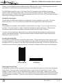
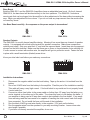
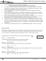
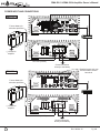
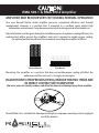
RMA 500.1 & RMA 500.4 Amplifier Owner’s Manual
Rev. 09-Mar-10
Pg. 1/8
RMA 500.1 & RMA 500.4 Amplifier Owner’s Manual
Thank you for purchasing a Roswell Marine Audio (RMA) Amplifier. Since 1998 Roswell has been the
world leader in wakeboard towers and accessories in the marine industry.
This RMA Marine amplifier uses a Full Range Class G/H topography that significantly improves
efficiency while enhancing sound quality. Do not be fooled by the small size. Class G/H amplifiers
make more power for their size than traditional designs and offer much lower THD and higher damping
factors than Full Range Class D designs.
Installation Instructions
Roswell Wake Air RMA series amplifiers are designed for easy installation in your boat. To ensure
proper operation of your new investment, please follow the suggestions we have listed below:
Warning
Please check the suitability of the installation location before you begin. Do not cut any of the boats
structure. Pay close attention to what is behind any bulkheads, panels and carpet. Often the boat
manufacturer will hide wires and cables in the exact location you may wish to install in.
If you do not have experience with automotive or marine electrical and mechanical systems please
contact a professional installer. Paying a qualified installer is almost always cheaper than paying a
dealership to repair your boat.
Location of the Amplifier
The amplifier must be securely mounted to a solid surface. Please select a dry location such as in the
storage compartment. Do not mount the amplifier to any area that may have excessive vibration (like
the subwoofer box) or under any cup holder drain lines that may leak water. Position the amplifier in an
area that receives sufficient airflow and mount it vertically or completely flat for proper heat dissipation.
Vertical Mount
Flat Mount
Supplying Enough Power
Your amplifier converts power, or current, from your boat’s electrical system and turns it into high power
audio energy. If the amp does not get all the power it needs, it will not produce its full output. If the
voltage or current drops too low, the amplifier will drop below it’s rated output. Make sure your boats
charging system is in good working order. Any hi-performance audio amplifier will increase the demand
on your alternator and battery. If you are unsure, have your charging system tested by a professional
technician.
Rev. 09-Mar-10
Pg. 2/8
RMA 500.1 & RMA 500.4 Amplifier Owner’s Manual
The Ground
Warning: Read this carefully
The ground wire should be connected directly to the battery of your boat.
Remember, the ground must carry the same high current as the positive wire.
To reduce the risk of noise, run all signal cables away from any power supplying wires.
Running the cables
Carefully run your power wires and ground wires to the battery. Use 4 gauge wires for your ground and
for your positive power cable. We strongly recommend using a 60 amp inline fuse for each amplifier,
installing it no further away than 18” from the battery for safety. A full RMA Wiring Kit can be purchased
separately through a Roswell Wake Air dealer and we highly recommend using our wiring kit as it
ensures high quality wiring and fusing.
Input Section
Due to the wide range of head unit output configurations all RMA amplifiers have an adjustable input
sensitivity or “GAIN”. The gain is not a volume or a power limiting control. It properly matches the input
of the amplifier to the output of the head unit and makes the amplifier more sensitive to input from the
stereo. With the gain up, the amplifier will reach maximum output at a lower volume setting on the deck.
At higher gain settings the amplifier becomes more sensitive to noise from the boats electrical system.
Try to run the gain at the lowest setting possible for your system for the best sound quality while still
achieving full power output.
There is no correct gain setting for all applications as head unit preamp outputs vary. Since speakers
have different power requirements to reach the same output, the gain is most often needed to compensate for these differences. If you tried to set all the gains at half way, you would probably have found the
system did not sound very good. Using good judgment and listening carefully to each speaker is still the
best way to tune a system.
RMA 500.1
RMA 500.4
Crossover Controls
A crossover is a device the removes unwanted frequencies from a speaker or amplifier. A tweeter can
easily be blown by bass frequencies if they are not filtered out. A subwoofer will not sound natural if it is
playing mid range frequencies. A crossover removes the unwanted frequencies from the speaker. Careful adjustment is needed to ensure that all speakers are playing the right frequencies and that they are
left with no low spots in the frequency response.
RMA 500.1
RMA 500.4
Rev. 09-Mar-10
Pg. 3/8
RMA 500.1 & RMA 500.4 Amplifier Owner’s Manual
Bass Boost
Both the RMA 500.1 and the RMA 500.4 amplifiers have an adjustable bass boost. On the 4 channel
RMA 500.4, the bass boost will be directed only to the front speakers. The RMA 500.1 includes a
remote gain that can be plugged into the amplifier to allow adjustment of the bass without accessing the
amp. Begin your adjustment at low volume. If you do not hear any improvement then the woofer does
not need any boost.
Use Bass Boost carefully - the response on the power output is tremendous!
RMA 500.1
RMA 500.4
Speaker Outputs
The RMA 500.4 is a multi channel amplifier design. Meaning it has more than one channel of speaker
outputs. It is equipped with a block style terminal for speaker connection. Make these connections
carefully and neatly. Strip your wire back ½” and twist the exposed leads. Insert them into the appropriate spot on the block terminal. Make sure that there are no loose or frayed strands of wire sticking out.
If a wire comes in contact with another wire, the amplifier will go into protection mode. Fasten the wire
in place with a small termination (bladed) screw driver.
Know your total ohm load before you make any connections.
RMA 500.1
RMA 500.4
Installation Instructions
1.
2.
3.
4.
5.
6.
Disconnect the negative cable from the boat battery. Tape up the end so it is isolated from the
battery.
Run a red 4 AWG wire from the battery to the amplifier. Plan this part of the installation carefully.
This cable will carry a very high current. If it should short to any metal and is not properly fused
it could catch fire.
Connect an inline fuse holder to the power cable no further than 18” away from the battery connector terminal on the other end of the cable. The closer this fuse is to the battery the better. If
one amplifier is being used a 60 amp fuse needs to be installed in the fuse holder. If two amplifiers are being used the fuse needs to be capable of handling the total current load of all amplifiers connected. Do not install the fuse until the end of the installation.
Run the black 4 AWG ground wire directly to the negative (-12V) pole on the battery.
Run the speaker wires from the speakers to your amp mounting location. Leave some extra
wire length if possible.
If you have not already mounted the amplifier, do so now.
Rev. 09-Mar-10
Pg. 4/8
RMA 500.1 & RMA 500.4 Amplifier Owner’s Manual
7.
8.
9.
10.
11.
12.
13.
Connect the power and the ground wires to the amplifier.
** Only after this step should you install the fuse at the battery**
Connect the remote wire (blue wire on most head units) from the head unit to the “TURN ON”
connection of the amplifier. Now is a good time to turn on the amplifier for the first time. Make
sure it turns on properly and does not go into protection.
With the amplifier turned off, connect the speakers to the amplifier making sure the polarity
(+ and -) are correct.
Connect the RCAs to the amplifier. On a RMA 500.1 amplifier the “SLAVE OUT/IN” connections
are to connect multiple amps in parallel. The white end of the RCA cable will go into CH1 and
CH3 and the Red end will go into CH2 and CH4 on a RMA 500.4 amplifier.
Now you are ready to play your stereo system for the first time. It is best to leave the “GAIN” all
the way down at first. Start with the head unit volume low and work your way up.
This amplifier is set to a standard setting and may need some adjustment. Take your time and
make only one adjustment at a time. It may take some time to fully adjust your system. During
this time your amplifier is drawing current from the battery. You should check the battery voltage
from time to time and recharge it if it gets low. The battery’s voltage can affect the way the ampli
fier performs.
You have now completed the install of your new RMA Marine Amplifier. Thank you and enjoy.
Protection Codes
This amplifier is equipped with an advanced diagnostic system controlled by the microprocessor. In the
event that this unit goes into protection for any reason it will flash the status light found on the control
end of the amplifier. The different sequences indicate the “Code” for faster trouble shooting.
End Panel Bicolor LED: Default behavior is to have the panel light green:
Code 11:
Thermal Protection
The amplifier has reached its maximum safe operating temperature
● ● ● ● ● ● ● ● ● ● ● ● ● ● ● ●
R
R
G
G
R
R
G
G
R
R
G
G
R
R
G
G
G: Green Light
R: Red Light
G
Code 12:
Short Protection
The amplifier has detected a short circuit and shut down to avoid damage
● ● ○ ○ ● ○ ● ○ ○ ○ ○ ○ ○ ○ ○ ○
R
R
R
R
Code 13:
Repeated Short
The amplifier is detecting a constant short circuit condition and will not turn back on until it is resolved
● ● ○ ○ ● ○ ● ○ ● ○ ○ ○ ○ ○ ○ ○
R
R
R
R
R
Code 14:
Over Volt Protection
The battery voltage is unusually high and could damage the amplifier
● ● ○ ○ ● ○ ● ○ ● ○ ● ○ ○ ○ ○ ○
R
R
R
R
R
R
Rev. 09-Mar-10
Pg. 5/8
RMA 500.1 & RMA 500.4 Amplifier Owner’s Manual
POWER INPUT AND CONNECTIONS
RMA 500.4
RCA cable
Fuse at battery for
wire short protection
+
-
ry
tte
a
VB
12
(-) Ground to
amplifier
+12V wire (4 AWG)
Ground connection
directly to the battery
Supplied remote gain can
be connected to control
bass level
RMA 500.1
RCA cable
Fuse at battery for
wire short protection
+
-
ry
tte
a
VB
12
(-) Ground to
amplifier
+12V wire (4 AWG)
Ground connection
directly to the battery
Rev. 09-Mar-10
Pg. 6/8
RMA 500.1 & RMA 500.4 Amplifier Owner’s Manual
ROSWELL MARINE AUDIO WARRANTY AND SERVICE GUIDELINES
Roswell Wake Air warrants all new RMA Series amplifiers against defects in material and workmanship
for a period of ONE (1) YEAR from the original date of purchase. This warranty is not transferable and
applies only to the original retail purchaser from an authorized Roswell Marine Audio retailer. Upon
inspection by Roswell Wake Air, should service be necessary under this warranty for any reason due to
manufacturer defects, Roswell Wake Air will, at our own discretion, repair or replace the defective
product with new or similar conditioned product at no charge.
THIS WARRANTY DOES NOT COVER INSTALLATION OR DAMAGE RESULTING FROM ACCIDENT,
MISUSE, ABUSE, IMPROPER WIRING, OPERATION OUTSIDE OF THE MANUFACTURERS RECOMMENDATIONS OR SPECIFICATIONS, OR AGAINST INSTRUCTIONS IN OWNERS MANUAL. IN
ADDITION, ANY PRODUCT THAT HAS BEEN OPENED, TAMPERED WITH OR MODIFIED, OR IF
ANY SERIAL NUMBERS HAVE BEEN REMOVED, WILL NOT BE COVERED BY ANY PART OF THE
MANUFACTURES WARRANTY.
All warranty claims must first be made in direct contact with Roswell Wake Air’s warranty department.
When first contact is made the warranty representative will issue an RA # to open a claim. All warranty
returns should be sent to Roswell Wake Air freight prepaid and must be accompanied by proof of
purchase (a copy of original sales receipt). Direct returns from consumers or non-authorized retailers
will be refused unless specifically authorized by Roswell Wake Air with a valid return authorization
number (RA#).
All warranty returns should be packed in the original packaging and must be accompanied by a copy of
the original sales receipt. Product damage during shipping will not be covered under this warranty. The
customer or retailer may choose to have this damage repaired at the normal “Out of Warranty” repair
cost.
In no event will Roswell Wake Air be liable for incidental, consequential, or other damages resulting
from the use of this product. This includes but is not limited to, damage of hearing, property of person,
damage based upon inconvenience or on loss of use of the product, and to the extent permitted by law,
damages for personal injury.
This warranty applies to products being sold and used in the United States of America and Canada. In
all other countries please contact your authorized Roswell Wake Air representative.
For warranty and non-warranty repairs, please contact Roswell Wake Air:
Phone: 1.780.962.0868
Email: [email protected]
www.roswellwakeair.com
Rev. 09-Mar-10
Pg. 7/8
SPECIFICATIONS
OUTPUT POWER (RMS) @ 1% THD 100KZ 14.4VDC
POWER OUTPUT @ 4Ω
POWER OUTPUT @ 2Ω
POWER OUTPUT @ 1Ω
POWER OUTPUT @ 4Ω BRIDGED
POWER OUTPUT @ 2Ω BRIDGED
TOTAL HARMONIC DISTORTION
FREQUENCY RANGE -3dB
CROSSOVER RANGE
BASS BOOST
S/N RATIO (A wtg) ref 4 Ω
SEPARATION
DAMPING FACTOR
25W out 4 ohms 1000Hz
INPUT SENSITIVITY (RCA)
INPUT IMPEDANCE
RMA 500.1
312 WATTS X 1 @ 14.4V
509 WATTS X 1 @ 14.4V
NOT RECOMMENDED
NA
NA
0.05%
20Hz-200Hz
30Hz-2000Hz
0-15dB @ 30Hz-125Hz
>82dB
NA
RMA 500.4
75 WATTS X 4 @ 14.4V
125 WATTS X 4 @ 14.4V
NOT RECOMMENDED
250 WATTS X 2 @ 14.4V
NOT RECOMMENDED
0.05%
1Hz-69KHz
55Hz-600KHz
0-15dB @ 42Hz
>90dB
>74dB
>1000
.3V-3.5V
10K OHMS
>1000
.3V-3.5V
47.5K OHMS
Rev. 09-Mar-10
Pg. 8/8
CAUTION!
RMA 500.1 & RMA 500.4 Amplifier
AMPLIFIER MAY BECOME VERY HOT DURING NORMAL OPERATION
Your new Roswell Marine Audio amplifier possesses exceptional efficiency and thermal
management. However, it is possible that, if mounted in a confined space and/or high
temperature environment, it may become extremely hot during periods of extended use.
Special attention must be given during the installation process to optimize cooling efficiency. An
unobstructed airflow around the amplifier’s heat sink is required to enable proper cooling.
For optimal performance Roswell recommends mounting the amplifier as follows:
Vertical Mount
Flat Mount
Mounting the amplifier in a position that does not enable proper cooling will affect the
performance of the unit and is strongly discouraged.
IN ADDITION TO PROPER MOUNTING, ENSURE THAT NO ITEMS ARE
IN DIRECT CONTACT WITH AMPLIFIER
Life vests, wet suits, towels, coolers, and other like items must be kept away from amplifier.
Roswell Wake-Air is not liable for damage resulting from improper mounting and/or negligent
use of this product.