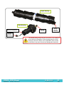
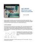
1
Using a cabled receiver with the ability to deliver real time data. DOC-5073-10 20 Mar 2014 Summary of Manual This manual is intended to provide our users with the information they require to use our VR2C receiver. VEMCO highly recommends that the user fully read the manual before using the equipment or VUE software. Section 1: Introduction Getting to know the VR2C receiver Section 2: Getting Started Getting the VR2C ready, including powering the VR2C and initial tests Section 3: Communication How to communicate with the VR2C using either VUE software or ASCII commands Section 4: Deployment Important points to consider in a VR2C deployment plan Section 5: Maintenance How to maintain the equipment and prepare it for storage Section 6: Troubleshooting Solutions to potential issues that may arise Section 7: Appendices For the latest versions of user manuals and software, visit www.vemco.com. Table Of Contents 1 Introduction ....................................................................... 1 1.1 System Overview .............................................................................................................. 1 1.1.1 VR2C Modes of Operation ......................................................................................... 1 1.1.1.1 Suspend Mode ................................................................................................... 1 1.1.1.2 Record Mode ...................................................................................................... 1 1.2 VR2C Case....................................................................................................................... 2 1.3 Case Parts ........................................................................................................................ 3 1.3.1 Status Light (LED) Flashes ........................................................................................ 4 1.3.2 External Connector .................................................................................................... 5 1.3.2.1 External Power ................................................................................................... 5 2 Getting Started .................................................................... 6 2.1 Dummy Plug and Locking Collar ....................................................................................... 6 2.2 Connect VR2C to PC ........................................................................................................ 7 2.2.1 Connecting a cable to the VR2C ................................................................................ 7 2.2.2 Connecting to the PC................................................................................................. 8 2.2.2.1 VR2C Communications Package – RS232 ......................................................... 8 2.2.2.2 RS232 Screw Terminal and VR2C External Cable Pinout................................... 8 2.2.2.3 USB to RS232 Converter Installation .................................................................. 9 2.2.2.4 VR2C Communications Package – RS485 ....................................................... 10 2.2.2.5 RS485 Screw Terminal and VR2C External Cable Pinout................................. 10 2.2.2.6 USB to RS485 Converter Installation ................................................................ 10 2.3 Communication Tasks .................................................................................................... 11 2.4 Testing ............................................................................................................................ 12 2.4.1 In-Air Test ................................................................................................................ 12 2.4.2 In-Water Test ........................................................................................................... 12 3 Communication ................................................................. 13 3.1 VUE Software Communication........................................................................................ 13 3.1.1 Installing VUE Software ........................................................................................... 13 3.1.2 Establish Communication ........................................................................................ 14 3.1.2.1 Network Link (optional) ..................................................................................... 15 3.1.3 Change Baud Rate .................................................................................................. 17 3.1.4 Logging Options ...................................................................................................... 18 3.1.4.1 Ancillary Logging .............................................................................................. 18 3.1.4.2 Diagnostic Logging ........................................................................................... 18 3.1.5 Real Time Mode Configuration ................................................................................ 19 3.1.6 Start a Study ............................................................................................................ 21 3.1.7 Offload Data ............................................................................................................ 23 3.1.8 Enter Suspend Mode ............................................................................................... 24 3.1.9 Additional Device Options ........................................................................................ 25 3.1.9.1 Install Firmware ................................................................................................ 25 3.1.9.2 Reset Battery Usage Indicator .......................................................................... 27 3.1.9.3 RS485 Termination ........................................................................................... 27 3.1.10 Set Local options ..................................................................................................... 28 3.1.11 Disconnect Communication with Receiver ............................................................... 28 3.2 ASCII Communication..................................................................................................... 29 3.2.1 Setting Up ASCII Communication ............................................................................ 29 3.2.2 ASCII Command Set List ......................................................................................... 31 3.2.3 Enabling/Disabling Receiver Serial Transceivers ..................................................... 31 3.2.4 ASCII Command/Response Format ......................................................................... 32 3.2.5 ASCII Command Details .......................................................................................... 32 3.2.5.1 Serial Communication Port Control ................................................................... 33 3.2.5.1.1 BAUDRATE=x ............................................................................................... 33 3.2.5.1.2 QUIT.............................................................................................................. 33 3.2.5.2 Basic Receiver Control/Status .......................................................................... 33 3.2.5.2.1 INFO.............................................................................................................. 33 3.2.5.2.2 STATUS ........................................................................................................ 33 3.2.5.2.3 START .......................................................................................................... 34 3.2.5.2.4 STOP ............................................................................................................ 34 3.2.5.2.5 TIME=x .......................................................................................................... 34 3.2.5.2.6 ERASE ......................................................................................................... 35 3.2.5.2.7 STORAGE ..................................................................................................... 35 3.2.5.2.8 RESETBATTERY .......................................................................................... 35 3.2.5.3 Real-Time Mode (RTM) .................................................................................... 36 3.2.5.3.1 RTM232 ........................................................................................................ 37 3.2.5.3.2 RTM485 ........................................................................................................ 37 3.2.5.3.3 RTMNOW ...................................................................................................... 37 3.2.5.3.4 RTMPROFILE=x ........................................................................................... 37 3.2.5.3.5 RTMINFO ...................................................................................................... 40 3.2.5.3.6 RTMOFF ....................................................................................................... 41 3.2.5.3.7 RTMAUTOERASE=x ..................................................................................... 41 3.2.5.4 Detection Log Manual Retrieval (Advanced User Feature) ............................... 41 3.2.5.4.1 READBEG ..................................................................................................... 41 3.2.5.4.2 READEND ..................................................................................................... 42 3.2.5.4.3 READREC ..................................................................................................... 42 3.2.5.4.4 READACK ..................................................................................................... 42 3.2.6 ASCII Usage Case Examples .................................................................................. 42 3.2.6.1 Example 1: Starting a Study ............................................................................. 42 3.2.6.2 Example 2: Entering Real-Time Mode .............................................................. 43 3.2.6.3 Example 3: Updating the VR2C Clock .............................................................. 43 3.2.6.4 Example 4: Erasing Data Logs.......................................................................... 44 3.2.6.5 Example 5: Placing VR2C in Suspend Mode .................................................... 44 4 Attachment Methods ........................................................... 45 4.1 Deployment Facts/Tips ................................................................................................... 45 4.1.1 Mooring ................................................................................................................... 45 4.1.2 Spacing ................................................................................................................... 45 4.1.3 Biofouling ................................................................................................................. 45 4.2 External Cable ................................................................................................................ 46 4.3 Case External Dimensions .............................................................................................. 46 5 Maintenance ..................................................................... 47 5.1 Cleaning Instructions ...................................................................................................... 47 5.2 Battery ............................................................................................................................ 47 5.2.1 Battery Life .............................................................................................................. 47 5.2.2 Battery Installation/Replacement ............................................................................. 48 5.2.2.1 Opening the VR2C Case .................................................................................. 48 5.2.2.2 Disconnecting and Removing Battery ............................................................... 51 5.2.2.3 Inserting or Replacing Battery ........................................................................... 52 5.2.2.4 O-ring Inspection .............................................................................................. 53 5.2.2.5 Closing the VR2C Case .................................................................................... 54 5.2.2.6 Resetting the VR2C Battery Usage Indicator .................................................... 56 6 Trouble Shooting ............................................................... 57 6.1 6.2 Dented Threads .............................................................................................................. 57 Pressurized Case ........................................................................................................... 57 7 Appendices....................................................................... 58 7.1 7.2 7.3 7.4 Contact Information ........................................................................................................ 58 VR2C Specifications ....................................................................................................... 58 Warranty and Disclaimer................................................................................................. 60 Index............................................................................................................................... 61 © (2014) AMIRIX Systems Inc. All rights reserved. The information contained herein includes information which is confidential and proprietary to AMIRIX Systems Inc. and may not be used or disclosed without prior written consent of AMIRIX Systems Inc. The Bluetooth® word mark and logos are owned by the Bluetooth SIG, Inc. and any use of such marks by AMIRIX Systems Inc. is under license. Other trademarks and trade names are those of their respective owners. 1 Introduction 1.1 System Overview The VR2C joins the world of instant communication by allowing received data from VEMCO’s coded tags to be sent in real time to third-party equipment. That equipment could be a PC, a serial terminal, a third-party datalogger, or any ASCII compatable device. Along with tag data, the VR2C can record and send information about the temperature and tilt of the receiver. How the data is sent is easily customized to fit your needs, and can be setup whenever you are in communication with the VR2C. The VR2C retains the submersible plastic corrosion resistant high pressure case VEMCO receivers are known for while adding a cabled RS232/RS485 external connector. This connector, along with real-time communication, provides the option of powering the VR2C from an external source as well as from the receiver’s internal single Lithium D cell battery. 1.1.1 VR2C Modes of Operation The VR2C is usually in one of two operational modes – either acoustically dormant in Suspend mode or actively listening and recording detections in Record mode. 1.1.1.1 Suspend Mode Suspend mode is a low power state used when the VR2C is being shipped or in storage for an extended period of time. When in Suspend mode, the receiver will not detect or record tag information. For details on how to place the VR2C in Suspend mode, see section 3.1.8 if you are using VUE or section 3.2.5.2.7 if you are using ASCII commands. The VR2C is shipped in Suspend mode with the internal battery connected. Always put the receiver in Record mode (begin a study) before deployment. 1.1.1.2 Record Mode Record mode allows the VR2C to detect and record tag information, therefore it is the mode used during testing and deployment. Because the VR2C is shipped and stored in Suspend mode, where it is acoustically dormant, it must be put in Record mode before it can detect tags. Instructions for entering Record mode using VUE are found in section 3.1.6 and the ASCII command is found in section 3.2.5.2.3. VEMCO - VR2C Manual 20 Mar 2014 1 1.2 VR2C Case The VR2C is housed in a black plastic high pressure case. The various external parts of the receiver are identified and briefly explained in the next section (1.3). A crucial part of the VR2C is the hydrophone, located at one end of the receiver. The hydrophone is similar to a microphone – it “listens” for sounds and transfers them to the electronics inside the receiver. Be very careful not to bump the hydrophone against hard surfaces or damage may occur that could compromise the receiver’s ability to detect tags. Do not bump the hydrophone or the receiver may be damaged and unable to detect transmitters. The VR2C only listens to the frequency selected at the time of ordering: the VR2C-69kHz operates at 69 kHz and the VR2C-180kHz operates at 180 kHz. The receiver frequency chosen depends on the type of coded tags that will be used. For example, if tags operating at 69 kHz are being used then the VR2C-69kHz must be used. The only externally distinguishable physical differences between the VR2C-69kHz and the VR2C-180kHz are the size of the hydrophone and the colour of the text on the serial number band. The VR2C-180kHz hydrophone is smaller than the VR2C-69kHz hydrophone, as shown in the photos below. The case dimensions are found in section 4.3. The two versions of the VR2C operate in the same manner so they’ll be discussed simply as a “VR2C” in this manual. Visible External Differences: 1. Hydrophones are different sizes 2. Serial Number label is a different colour. Blue = 69 kHz Green = 180 kHz VR2C-69kHz The VR2C can be powered externally from a DC power source and/or internally by a single “D” size 3.6 Volt Lithium battery (see section 5.2). The VR2C is shipped in Suspend mode, with the internal battery connected, so the case does not need to be opened until the battery must be replaced. VR2C-180kHz Case does not need to be opened until battery must be replaced. WARNING The VR2C pressure case and seal have a static depth rating of 500 meters (730 psi). Physical shocks to the receiver, such as bumping into a solid object, at any depth can result in a considerably higher pressure on the casing than just the depth pressure, and water may enter the VR2C case. As well, if the O-ring seals have been compromised, water may also enter the receiver case. If you are suspicious that water has entered the receiver, then follow the suggestions found in section 6.2. VEMCO - VR2C Manual 20 Mar 2014 2 1.3 Case Parts Hydrophone: The receiver’s “microphone” and most delicate part. Do not bump the hydrophone or the receiver may be damaged and unable to detect transmitters. Under no circumstance should you unscrew the upper housing as this will cause serious internal damage to the VR2C. Status Light (LED)/Release Valve: The light flashes red to indicate the receiver’s status. Section 1.3.1 has the full description. The Release Valve will open if the internal pressure is greater than the external pressure (see section 6.2). Never cover this valve. Cable Tie Groove: These grooves (there are two) are used to attach the VR2C to a line. Identification Label: Contains product name and model number, contact information, serial number, and important warnings. At a glance, the blue text indicates receiver is a VR2C-69kHz and green text indicates it’s a VR2C-180kHz. Cable Tie Groove: This is the second of the two grooves used for attachment. Receiver Locking Ring: Allows access to the internal battery and should only be opened when replacing the internal battery (see section 5.2.2). Do not open Threaded Endcap unless you are replacing the battery. Cable Connector: A locking collar holds the cable’s 8-pin connector to the VR2C external connector (shown at right). More information about the external connector is found in section 1.3.2. More information about the external cable is found in section 4.2. VEMCO - VR2C Manual 20 Mar 2014 3 1.3.1 Status Light (LED) Flashes The red Status Light on the side of the VR2C case flashes based on the task being performed or the status of the receiver. The flashes can be interpreted using the table below. The Status Light is an LED (Light Emitting Diode) and has been referred to as such in past documentation. VR2C LED Flashes Interpretation of Flashes No flash Not powered or in Suspend Mode Two quick flashes every 5 seconds VR2C is in record mode (records any received pings) Two quick flashes every 10 seconds The VR2C memory is full One short flash An acoustic ping was received One long flash A complete detection was written to memory When the VR2C is first powered, it will flash four times to indicate that it has successfully completed the start-up process. After the four flashes, the Status Light will begin flashing based on its status. The most common flash pattern is two quick flashes every 5 seconds to indicate the receiver is recording. If the receiver’s Status Light flashes anything other than what is explained in this section, then contact VEMCO’s Customer Support team for assistance. VEMCO - VR2C Manual 20 Mar 2014 4 1.3.2 External Connector The VR2C uses a submersible connector (SubConn PN: MCBH8M) to allow for a cabled interface to a customer PC, a third-party data logger, a modem, or other supported host device. The VR2C external connector supports both RS232 and RS485. By using an RS232 or RS485 cable, communication with the VR2C can occur through either serial interface, although not both at the same time. Specifications for the cable are found in section 4.2. RS232 communication can only be used for cables that are less than 15.2 m (50 feet). The VR2C connector pin-out, as shown from the external view, is listed below. VR2C external connector pin-out Pin # Function 1 External DC POWER - 2 RS485 D+ 3 External DC POWER + 4 RS485 D- 5 RS232 TX (from host to VR2C) 6 RS232 RX (from VR2C to host) Face-on View 7 CGND (looking into pins) 8 No Connect Never deploy the VR2C with the connector exposed. It must be connected to a cable or the Subconn dummy plug when deployed. 1.3.2.1 External Power The VR2C external connector allows for the receiver to be powered from an external power source. The external power specifications are: External DC Voltage: +10 volts to +32 volts Typical Power Consumption (@12V): 2 – 15 mA (Record Mode) VEMCO - VR2C Manual 20 Mar 2014 5 2 Getting Started After the VR2C has been removed from the packaging and inspected for any damage that may have occurred during shipping, test to ensure you can communicate with the receiver and that the receiver is working properly. Each of the steps listed below are explained in detail later in this manual. 1. 2. 3. 4. 5. Unscrew the Locking Collar from the VR2C external connector (section 2.1). Connect the VR2C to the PC using the VR2C Communication Kit (section 2.2). Use the VUE Software to communicate with the VR2C (section 3.1.2) and start a study (3.1.6) Ensure the VR2C can detect tags by performing an in-air test (section 2.4). Place the VR2C back in Suspend Mode (section 3.1.8) if you are storing it for an extended time period. 6. Disconnect the VR2C from the VR2C Communication Kit cable and reinstall the Dummy Plug and Locking Collar for transportation or storage. 2.1 Dummy Plug and Locking Collar Locking Collar The dummy plug is used to protect the external connector from moisture and damage while it is not connected to the cable. The dummy plug is held in place on the VR2C with a threaded Locking Collar. The VR2C is shipped with the locking collar attached to the external connector to give the pins additional protection during shipping. When the VR2C is stored, the dummy plug and locking collar should be in place and will need to be removed before communicating with VUE. The dummy plug should be returned to the external connector when a cable is not connected to the receiver. Dummy Plug Follow the instructions below to remove the Dummy Plug, and reverse the steps to re-install it. STEP 1 Twist the Locking Collar (see arrow) counterclockwise until it separates from the receiver. Slide it away from the connector. VEMCO - VR2C Manual STEP 2 Grasp the dummy plug at the connector and pull straight back to remove it from the VR2C case. Grip the connector rather than the ball end of the dummy plug to reduce the chance of damage occurring to the plug. 20 Mar 2014 6 2.2 2.2.1 Connect VR2C to PC Connecting a cable to the VR2C Connect the 5 m cable supplied in the communication package (see section 2.2.2) to the VR2C by following the steps below. This procedure is the same for any cable but we’re starting with the short cable to familiarize you with the receiver and also to test the receiver. The pin-out of the connector is found in section 1.3.2. STEP 1 Line up the gap on the cable’s connector with the gap on the VR2C’s external connector. STEP 2 Grasp the cable at the connector and push straight in until the gap between the two connectors is closed. IMPORTANT: Grip the connector rather than the cable. This reduces damagecausing strain on the cable. VEMCO - VR2C Manual STEP 3 Slide the Locking Collar located on the external cable (identified in photo) over the connector and twist it clock-wise until it stops. There shouldn’t be a gap between the metal connector and the edge of the Locking Collar. 20 Mar 2014 7 2.2.2 Connecting to the PC Connecting a VR2C to a PC in a lab setting is best accomplished with the use of a VR2C Communication package. There are currently two different VR2C Communication packages reflective of the different cables that can be used for communication, RS232 or RS485. The communication packages are intended to allow the customer to communicate with the VR2C in an office or lab setting using a PC. 2.2.2.1 VR2C Communications Package – RS232 The VR2C Communication Package for RS232 consists of: • • • • USB to RS232 converter (US232R-10 device available from FTDI Chip) DB9 to screw terminal block (RS232 version) VR2C external cable with flying leads VEMCO Product CD including VUE software USB to RS232 converter and terminal block 2.2.2.2 RS232 Screw Terminal and VR2C External Cable Pinout Screw Label Signal Name Flying Lead from VR2C Cable S CGND Silver G RS-232 RX (to PC) Green W RS-232 TX (from PC) White R DC + (+12V to +32V) Red B DC - Black Screw labels on terminal block Flying Lead connected to terminal block NOTE: It is not necessary to provide external DC power to the VR2C provided the internal battery is connected. If providing external DC power via the screw terminal block, caution must be exercised to ensure that the voltage polarity is correct. VEMCO - VR2C Manual 20 Mar 2014 8 2.2.2.3 USB to RS232 Converter Installation When the USB to RS232 converter is plugged into a USB port on a PC, Windows® configures it as a virtual COM port and assigns a COM port number to it. This COM port number should be noted as the VUE software utility needs this information to communicate with the VR2C. 1. Plug the USB to RS232 converter into a USB port on the PC. 2. When Windows detects it, you should see a “Found New Hardware Wizard” dialog box. The device is identified as “US232R”. Select “Yes, This time only” and click “Next”. 3. Select “Install software automatically (recommended)” and click “Next” and wait. 4. Click “Finish”. 5. You should see another “Found New Hardware Wizard” dialog box. This time the device is identified as “USB Serial Port”. Select “Yes, This time only” and click “Next”. 6. Select “Install software automatically (recommended)” and click “Next”. 7. Click “Finish”. 8. Open the Windows® Control Panel and then select “System” to open the System Properties window. 9. Click the “Hardware” tab in the System Properties window and then click on the “Device Manager” button. The Device manager screen will open with a list of all devices installed on PC. 10. Click the + symbol next to “Ports” in the device list to expand the ports list. You should see an entry “USB Serial Port (COM x)” where the “x” is a number. Record the “x” number for future reference when using the VUE software. In the example shown below, the COM number is 4. The automatic install may not work – it depends whether the drivers are available on that PC or not. If not, you need to tell Windows where to find the driver (e.g. local drive or wherever). The drivers can be downloaded from http://www.ftdichip.com/Drivers/VCP.htm. VEMCO - VR2C Manual 20 Mar 2014 9 2.2.2.4 VR2C Communications Package – RS485 The RS485 communication package consists of: • • • • Sealevel USB to RS485 converter and Sealevel CD DB9 to screw terminal block (RS485 version) VR2C external cable with flying leads VEMCO Product CD including VUE software USB to RS485 converter and terminal block 2.2.2.5 RS485 Screw Terminal and VR2C External Cable Pinout Screw Label Signal Name Flying Lead from VR2C Cable S CGND (Shield) Silver G RS485 D- Green W RS485 D+ White R DC + (+12V to +32V) Red B DC – (GND) Black Screw labels on terminal block Flying Lead connected to terminal block NOTE: It is not necessary to provide external DC power to the VR2C provided the internal battery is connected. If providing external DC power via the screw terminal block, caution must be exercised to ensure that the voltage polarity is correct. 2.2.2.6 USB to RS485 Converter Installation Install the Sealevel software before inserting the USB connector into the PC. Follow the installation instructions that are on the Sealevel CD. During installation, the user needs to enter the Sealevel part number which is 2107. VEMCO - VR2C Manual 20 Mar 2014 10 2.3 Communication Tasks Communication with a VR2C receiver can be performed by using the VUE PC software or with ASCII commands. The VUE software is useful for in lab configurations, offloading complete VRL files from the receiver, or whenever you can communicate with the receiver using a laptop or PC. Detailed instructions for using VUE software are found in section 3.1. The simple ASCII command set is useful if you wish to create a script for grabbing real time detections or to interface the receiver to a simple data logger or other device that can support either RS232 or RS485 communications. For example, the VR2C has been successfully integrated into Oceanographic Buoys and ocean gliders. Detailed instructions for using ASCII Command Line are found in section 3.2. The table below lists different tasks performed with the VR2C receiver using both VUE software and ASCII commands, and the sections in this manual that contain the necessary details. Task Using VUE Using ASCII Communicate with VR2C 3.1.2 3.2.2 Start a Study (Record Mode) 3.1.6 3.2.5.2.3 Setup RTM (optional) 3.1.5 3.2.5.3 2.4 2.4 Offload data 3.1.7 - Erase data 3.1.6 3.2.5.2.6 Suspend recording for storage 3.1.8 3.2.5.2.7 Test VEMCO - VR2C Manual 20 Mar 2014 11 2.4 Testing Before deploying a VR2C, it is wise to test it with a tag to verify that it has been configured appropriately and is operating properly. This test also creates a VRL file containing all the configuration information for this receiver. It is important to keep the VRL files as a record of the receiver’s configuration. Tests can, and should, be done in both air and water. The VR2C can detect coded tags in air, but at a much reduced range compared to their range capabilities in water. 2.4.1 In-Air Test Perform air tests away from electrical noise sources such as motors, PC screens, or fluorescent lights. Before beginning the test, ensure the clock of the PC to be used is set to the correct local time and time zone. Follow the steps listed below to perform the in-air test. 1. Connect the VR2C to your PC or terminal using the VR2C external cable. 2. Enter Record Mode. In VUE, this means starting a study (see section 3.1.6). If you’re using ASCII commands, then follow the instructions in section 3.2.5 to enable Record Mode and RTM output. 3. Activate a tag that operates on the same frequency as the VR2C receiver and place it near the hydrophone at the distance listed below. Position the tag so the side of the tag is facing the side of the VR2C hydrophone, as shown in the photo. − If using a 69 kHz tag, place the tag less than 30 cm (12”) away from the hydrophone. − If using a 180 kHz tag, place the tag less than 8 cm (3”) away from the hydrophone. 4. Wait while the VR2C records the tag near it. You can watch the flash patterns as the tag’s pings are detected and the data is stored in memory. Each faint flash of the Status Light (LED) is a received ping and a long, bring flash is a stored detection. If you are connected to VUE, you can see the detections in real time in the Detection Monitor section at the bottom of the Receiver tab window. If using ASCII commands, then verify that the VR2C RTM output on the PC or terminal contains the tag detection. 5. If the VR2C is not in communication with VUE while the tag has been pinging, then follow the instructions in section 3.1.2 to connect to VUE and check the number of detections and pings received listed in the receiver status information. 6. Offload the data that was collected during the test (section 3.1.7), creating a VRL file. 7. View the data to verify that the data was stored and retrieved without problems. Instructions for viewing data are found in the VUE manual. 2.4.2 In-Water Test Tests performed in water are almost identical to the in-air test explained above. The only difference is that the tags should be positioned farther from the receivers – 5 meters is suggested. In-water tests are often performed to establish an ideal range for the VR2C receivers in the environment in which they are moored. Details of conducting a Range Test are found at www.vemco.com. VEMCO - VR2C Manual 20 Mar 2014 12 3 Communication Communication with a VR2C receiver can be established using the VUE PC software or using ASCII commands. The VUE software is useful in lab configurations, offloading complete VRL files from the receiver, or whenever you can communicate with the receiver using a laptop or PC. Using VUE with a VR2C is explained in section 3.1 The simple ASCII command set, found in section 3.2, is useful if you wish to create a script for grabbing real time detections or to interface the receiver to a simple data logger or other device that can support either RS232 or RS485 communications. 3.1 VUE Software Communication VEMCO User Environment (VUE) PC software is used to configure, offload and analyze detection data from VEMCO acoustic receivers. Communication with a VR2C receiver can be performed by using the VUE software or by using ASCII commands. The VUE software is particularly useful in a lab setting for configuring, offloading (VRL files) or checking the status of a receiver when the receiver is connected to a Windows PC. 3.1.1 Installing VUE Software VUE requires a computer running either Windows XP SP3, Windows VISTA, Windows 7, or Windows 8. STEP 1 Run the latest “Install_VUE” application file. The latest file is always available from our website, www.vemco.com. STEP 2 Click “Next” when the Install Shield Wizard begins. STEP 3 STEP 4 Read the license agreement and select “I accept” and “Next” if you agree to the terms. Click “Next” to install VUE in the folder shown, or click “Change” to select a different folder. Continued… VEMCO - VR2C Manual 20 Mar 2014 13 STEP 5 STEP 6 Wait while the VUE software is installed. Click “Finished” to exit the setup wizard. Click “Next” when it becomes enabled. 3.1.2 Establish Communication Perform the following steps to establish communication with a VR2C from within VUE. STEP 1 Launch VUE software. STEP 2 Identify which Serial COM port the VR2C is connected to on your PC. STEP 3 Select “VR2C” from the list that appears. Select this Serial COM port within the ‘Home’ tab. The last COM port that was used within VUE will be identified with “(Last Used)” under the name. STEP 4 Identify the VR2C serial number as specified on the VR2C product label attached around the outside of the VR2C case. Enter this serial number in the box and click OK. The VR2C serial number may already be in the drop-down list if VUE has previously been used on this PC to connect to the VR2C. Click the down arrow to show the list of candidate VR2C serial numbers (see photo on right). If you are uncertain of the serial number, then click the “Scan” icon, and select the desired receiver when the connect option is offered. If the desired receiver is not the one offered, click the “Skip” option and continue to scan. Continued… VEMCO - VR2C Manual 20 Mar 2014 14 STEP 5 Wait for communication to be established. The VR2C receiver’s information and status are listed in the Receiver Tab. The tab name contains the VR2C serial number to which communication is established. The speed of communication can be adjusted (if desired) using the Serial Options window (section 3.1.3). 3.1.2.1 Network Link (optional) The VR2C can communicate with VUE remotely over an IP network (such as the internet). An RS232 or RS485 compatible serial device server must be connected to the VR2C and accessible through your local network connection before you begin. Click the “Add Network Link” icon (shown at left) in the Home tab and enter the necessary information in the Network Link window (shown at right) to setup the link. A host address (DNS name or IP address) and port number will be required. VUE will behave the same when communicating with the VR2C through the network link as it would through a direct cable with the exception of the baud rate. VUE cannot modify the configuration of any 3rd-party serial device server. Therefore, baud rates cannot be changed through a network link connection. Be sure to pre-configure the VR2C to the baud rate used by the serial device server it will be connected to. VEMCO - VR2C Manual VR2C baud rates cannot be changed through a network link connection 20 Mar 2014 15 The VR2C Receiver Tab Each receiver currently in communication with VUE has a tab at the top of the VUE window. This tab identifies the type and serial number of the receiver. Click on a tab to bring it to the front of all the tabs, making the receiver’s information visible. Receiver type and serial number The ribbon contains icons that allow the user to, among other things, offload data, start recording, enter suspend mode, upgrade firmware, and end communication. Remaining battery life Receiver information specific to this VR2C is contained in the center of the window. A tilt of 0° indicates VR2C is vertical with hydrophone pointing up. The Detection Monitor section displays detections that are received by the VR2C while it is connected to VUE. VEMCO - VR2C Manual Checking “Save to File” will create a file in which all received detections from that point forward are saved. The file name appears in the Detection Monitor display box and the file is saved to the Receiver Offload Storage Folder (the path to this folder can be specified within the Offload tab of the VUE Options menu, as explained in the VUE manual). 20 Mar 2014 16 3.1.3 Change Baud Rate There are two baud rates involved with the VR2C: 1. the baud rate used between the VR2C and VUE during the current communication session, and 2. the baud rate used for communication with a host device (datalogger, PC, serial terminal, etc.) after the VR2C has disconnected from VUE (section 3.1.5 contains more information about using a host). The default for both these baud rates is 9600bps but communication speeds can be increased to as high as 115200bps, depending on the type of cable being used for communication. Follow the steps listed below to change a baud rate. STEP 1 Establish communication between the VR2C and the VUE software (section 3.1.2). STEP 2 Click the Device Configuration icon (looks like a wheel cog) on the VR2C Receiver Tab’s ribbon. This icon is not available if communication between the VR2C and VUE is not established. STEP 3 Select “Serial Options” from the list that appears under the Device Configuration icon. This opens the VR2C Serial Options window. STEP 4 Identify the baud rate(s) you want changed and select the new value from the corresponding drop-down list. Click “OK”. If you are changing the Permanent Baud Rate, a window will appear to remind you that the new baud setting will remain in effect after VUE disconnects and RTM output will use this new baud. Communication speed (bps) between VR2C and VUE. Value is valid only for current communication session and returns to default (9600) when communication session ends. Communication speed (bps) between VR2C and an external host. Value is used after VR2C is disconnected from VUE and remains as set until you change it. VEMCO - VR2C Manual 20 Mar 2014 17 Baud Rates Two baud rates are shown in the information given on the VR2C Receiver Tab page. The “Current Baud” value is the baud rate used to communicate with VUE during this session. The “RTM Port” information includes the VR2C permanent baud rate, which may not be the same as the “Current Baud” value. RTM baud rate for communication with external host. Current baud rate for communication with VUE. 3.1.4 Logging Options 3.1.4.1 Ancillary Logging The VR2C has the ability to measure the temperature and/or tilt of the receiver and store this data in the receiver’s memory at an interval you specify. Keep in mind that the VR2C memory will fill quicker when this additional information is selected to be stored. 1. Select “Logging Options” 2. Select the desired information (temperature, tilt, or both). 3. Enter how often the data is to be stored in memory in the “Logging Period” box. 3.1.4.2 Diagnostic Logging Diagnostic Logging is an advanced setting feature which should only be selected when directed by VEMCO. This setting will log information about the receiver that may be helpful for VEMCO support staff when assisting a customer during the initial VR2C deployment setup. The Diagnostic Logging settings window allows the user to specify both how often and for what duration the diagnostic information will be stored to memory. Only enable if directed to do so by VEMCO. VEMCO - VR2C Manual 20 Mar 2014 18 3.1.5 Real Time Mode Configuration Real-time mode (RTM) refers to the ability of the VR2C to transmit tag detection information in the ASCII format on a user specified schedule over the RS232/RS485 serial port with or without user interaction. When enabled, RTM allows a host (for example: datalogger, PC, serial terminal) to simply listen to the VR2C serial port and pipe the receiver’s ASCII input data stream to a file or straight to a terminal where it can be easily read without complicated interpretation. As well as this automated data flow, RTM can also be used in a polled configuration where the VR2C outputs the ASCII tag detection information only when instructed to do so. VUE allows for basic RTM setup which will remain in the VR2C after it is disconnected from VUE, as explained in the steps below. STEP 1 Establish communication between the VR2C and the VUE software (section 3.1.2). STEP 3 Select “RTM Configuration” from the list that appears under the Device Configuration icon. STEP 2 Click the Device Configuration icon (looks like a wheel cog) on the VR2C Receiver Tab’s ribbon. This icon is not available if communication between the VR2C and VUE is not established. STEP 4 Select the radio button corresponding with the desired RTM mode: disabled, RS232, or RS485. NOTE: If “disabled” is selected, skip Step 5 as it does not apply. Continued… VEMCO - VR2C Manual 20 Mar 2014 19 STEP 5 Select the RTM Profile, Status Interval, and Auto Erase values as explained below. The baud rate value shown was selected in the VR2C Serial Options window (see section 3.1.3). Auto Erase forces the VR2C to automatically erase some of the older detection log data to ensure that a percentage of the detection log remains empty (a full log will not store new detections). If, for example, “10” is entered, then the receiver will automatically keep 10% of the detection log free after each RTM output, erasing data as required to do so. The erased data cannot be recovered from the VR2C and it is assumed it was captured by the host device. If the value is left at the default “0”, then the detection log can become full. Select the RTM Profile from the options explained below. Immediate Output (RTM Profile 0): Tag detection records are outputted as soon as they occur. A VR2C status line is also outputted based on the period set in the Status Interval box. This value must be between 1 second to 65535 seconds (default is 60 seconds). Setting the Status Interval to ‘0’ will disable the status line output (no status lines will be outputted). Tag records sent as soon as received; status line sent at set interval. Status Interval (SI) Block Output (RTM Profile 1): Status line and tag detection records received since the last transmission are outputted based on the period set in the Status Interval box. This value must be between 1 second to 65535 seconds (default is 60 seconds). Status line and tag records sent together at set interval. Polled Block Output (RTM Profile 2): Tag detection records only outputted when explicitly triggered using VR2C ASCII commands. Tag records only sent when requested. STEP 6 Click “OK” when settings have been configured. VEMCO - VR2C Manual 20 Mar 2014 20 3.1.6 Start a Study Setting up a study allows you to enter information in the VR2C, such as deployment location, a description of the study, or other helpful information that can be very useful when data is being organized in the VUE software. Start a study using VUE by following the steps below. STEP 1 Establish communication between the VR2C and the VUE software (section 3.1.2). Start a study to remove a VR2C from Suspend mode. VR2C receivers are shipped in Suspend mode. STEP 2 Click the circular red and blue “Start Recording” icon on the VR2C Receiver Tab’s ribbon. This icon is not available if communication between the receiver and VUE is not established. STEP 3 Review the PC clock time listed in the dialogue box that opens. The PC time and UTC offset must be correct as the VR2C will be set to UTC time based on these settings. If the PC time and UTC offset are correct, then click the “OK” button to continue. If the PC time and UTC offset are not correct, then click “Cancel” and make the necessary corrections before returning to start a study. CAUTION: It is vital that the PC clock and time zone must be correctly set to your local time before the VR2C is initialized. STEP 4 Select one of the three options displayed. 1.ERASE: use when the data stored in the VR2C has already been offloaded and securely backed up and you wish to erase the data and begin a new study. 2.OFFLOAD: use if there is any uncertainty about whether the data has been offloaded and securely backed up. 3.CANCEL: use when you wish to continue the study that is currently running in the VR2C receiver. No changes to the current study will be made. CAUTION: Verify you are communicating with the intended receiver before initializing/erasing receiver or data could be lost. Communication can occur with any receiver that is connected to the PC (including through Bluetooth®). WARNING Initializing the VR2C will erase the receiver’s memory. Offload detection logs before the VR2C is initialized. Continued… VEMCO - VR2C Manual 20 Mar 2014 21 STEP 5 Enter a description of the study in the Study Configuration window. This information is stored in the VR2C and offloaded with the data. It can be very useful when data is being organized in the VUE software. The station name can be selected from a list of existing stations (if a database is open) or by simply typing in the “Station Name” line to create a new station. If this station is a fixed position, then select the “Fixed Station Position” box and enter the Latitude and Longitude. If the fixed position is already entered for an existing station, then the lat/long data will appear as soon as the station name is selected from the drop-down list. Enter a description/title for this study. Select or enter a station name. Create a new station by entering the name in the Station Name line. Select “Fixed Station Position” to enter lat/long Advanced Settings include changing the map and blanking interval. Click OK to put the VR2C in Record Mode and begin the study. Choose unique station names for each deployment location. WARNING How do I know the VR2C is recording? Incorrectly changing the Advanced Settings can prevent the VR2C from detecting your tags. Only do so under VEMCO’s direction. Watch the red Status Light (LED) on the VR2C. Two quick, bright flashes every 5 seconds indicate the VR2C is in Record Mode. VEMCO - VR2C Manual 20 Mar 2014 22 3.1.7 Offload Data Detection and event data must be offloaded from a VR2C before it can be viewed. Follow the steps below to offload data using VUE. STEP 1 Establish communication between the VR2C and the VUE software (section 3.1.2). STEP 2 Click the “Offload data” icon in the VR2C Receiver Tab ribbon and choose one of the offload options listed: Offload All Data: offloads all data; will duplicate data already offloaded. Offload New Data: offloads only data that was stored since the last offload. Offload Raw Data: only use this when directed to do so by VEMCO. STEP 3 Review the PC clock time listed in the dialogue box that opens. The PC time and UTC offset must be correct as the VR2C will be set to UTC time based on these settings. If the PC time and UTC offset are correct, then click the “OK” button to continue. If the PC time and UTC offset are not correct, then click “Cancel” and make the necessary corrections before returning to start a study. CAUTION: It is vital that the PC clock and time zone must be correctly set to your local time before the VR2C is initialized. STEP 4 Wait until offloading is completed; progress is shown at the bottom of the VUE window. The name of the created file is displayed when the data has successfully been offloaded. If a VUE database is open when data is being offloaded from a VR2C, then an additional dialog box appears to ask if the offloaded data should be imported directly into the open database. If you select “Yes”, the data will be imported into the open database. If “No” is selected, then the data will not be imported. Regardless, the offloaded data will be saved to the directory in the format selected in the Offload tab of the Options window (see VUE manual for details). VEMCO - VR2C Manual 20 Mar 2014 23 3.1.8 Enter Suspend Mode Suspend mode is used to place the receiver in a low power state when it is being stored for an extended period of time. When in Suspend mode, the receiver will not detect or record tag information. Place the receiver in Suspend Mode by following the steps listed below. STEP 1 Click the “Enter Suspend Mode” icon on the receiver ribbon. STEP 2 Select “Yes” to turn off the acoustic receiver and enter Suspend Mode. STEP 3 Review the information in the warning box and click “OK” when finished. The Receiver Status line will report “Suspended” in flashing red text. When the receiver is about to be used again, communicate with a PC and start a new study (section 3.1.6) to turn the acoustic receiver on. The VR2C cannot detect acoustic tags when the acoustic receiver is in Suspend mode. VR2C receivers are shipped in Suspend mode. VEMCO - VR2C Manual Remove a VR2C from Suspend mode by starting a study. NEVER deploy a VR2C in Suspend mode. The VR2C cannot detect acoustic tags when in Suspend mode. 20 Mar 2014 24 3.1.9 Additional Device Options VUE allows you to set various VR2C configuration tasks through the use of the Set Device Options icon (wheel cog) on the VR2C Receiver tab ribbon. 3.1.9.1 Install Firmware Firmware refers to the internal software that operates a VR2C receiver. It is not to be confused with VUE, the PC software used to communicate with the receiver. Firmware updates are rare and will occur to either deal with a hardware change or occasionally for a significant addition to functionality. VUE 2.0.7 and greater has the ability to alert you if there is a new firmware update (feature can be disabled in the “Releases” tab of the Options window). VR2C firmware can only be updated when connected to VUE and not when using an ASCII interface. How to Update Firmware Using Automated Notification: If when you establish communication with the VR2C (see section 3.1) you receive a message indicating VUE has detected there is a firmware update, then use the instructions below to update your firmware. To learn what caused the firmware upgrade, use the “Click here to see more” option in the notice window. STEP 1 Decide if this is the right time to update the VR2C firmware by answering the following questions: 1. If the VR2C is currently being powered by the internal battery alone, does that battery have enough power to perform an update? If there is any doubt, then replace the battery or connect the VR2C to external power before proceeding. The VR2C could be damaged if power fails during the update process. 2. Has all the data been offloaded from the VR2C? Updating the firmware should not erase the data, but please take the precaution of offloading all data before updating. If you answered “No” to either of these questions, then click the “No” button in the notice window and either secure power to the VR2C or offload the data (see section 3.1.7), or both if necessary. The notice window will appear again the next time you connect to this VR2C, or use the instructions for manually updating the firmware found in the next section. If you answered “Yes” to both of these questions, then click the “Yes” button and continue with these instructions. Continued… VEMCO - VR2C Manual 20 Mar 2014 25 STEP 2 Assuming all data has been offloaded from the VR2C and is safely stored on your PC, click “OK” to acknowledge this warning and continue. STEP 3 Wait while the firmware is loaded into the VR2C. The status of the update is shown at the bottom of the screen. Click “OK” when the firmware is installed (see window below). STEP 4 Confirm that the VR2C has updated to the new firmware by checking that the firmware version number listed in the Receiver tab is correct. How to Update Firmware Using Manual Procedure: If the automatic notification doesn’t appear, then you can manually update the firmware. Before beginning, use Step 1 in the previous section to prepare for the update. Once the preparations are completed, select “Install Firmware” on the VR2C tab. A window titled “Select Firmware File” will appear. Select the most recent firmware file that matches your model of VR2C (based on operating frequency). VUE software will not let you install a firmware file for the incorrect model type. Click the “Open” button to continue. The rest of the procedure matches the instructions found in Steps 2 – 4 in the automated notification section. VEMCO - VR2C Manual 20 Mar 2014 26 3.1.9.2 Reset Battery Usage Indicator The Reset Battery Usage Indicator task should be performed immediately after replacing the VR2C’s internal Lithium D cell with a fresh battery. This causes the battery usage indicator to be reset to 0% used. Performing this task at any other time other than immediately after battery replacement will result in incorrect battery usage indicator results. 3.1.9.3 RS485 Termination If RS485 communication is being used with long cables and high baud rates (cable longer than 200m and baud rate higher than 57600, for instance), the system may require that RS485 terminations be enabled in order to have a reliable communication link between the VR2C and the RS485 host. If this is the case, RS485 termination can be enabled by selecting the RS485 Termination configuration box within the Serial Options window (under the Set Device Options icon). Enabling RS485 Termination causes the VR2C to consume more power while communicating with the host and should only be used if necessary. If there are multiple VR2C receivers attached to a single cable deployment, ensure that only the furthest VR2C on the cable has RS485 Terminations enabled. Enabling RS485 Termination causes VR2C to consume more power when communicating with the system host processor – only enable if necessary. VEMCO - VR2C Manual If multiple VR2C receivers are attached to a single cable deployment, then only the furthest VR2C on the cable should have RS485 Terminations enabled. 20 Mar 2014 27 3.1.10 Set Local options VUE allows the user to suppress certain pop-up queries that may occur when interacting with a receiver. If the user has suppressed one or more of these queries, the Set local options feature (icon shown at right) will become enabled on the VR2C Receiver Tab ribbon. This feature allows the user to change which pop-up queries are suppressed. To enable a query, select “Always Ask” and that query will be enabled the next time that feature is used. For example, if “Confirm before closing VR2C” is selected, then a query will open the next time a VR2C is closed. Changing a default response to a pop-up query, even while suppressing the pop-up query, is also possible in the VR2C Control Setting window. For example, consider the “Import offloaded file into current database” pop-up query. Assume that the use previously selected “No” as the answer to always use. If the user now wants the default answer to be “Yes”, then he/she can click the drop-down menu within the VR2C Control Settings dialog box and select “Yes” from the list. Be sure to select “OK” to apply the changes. 3.1.11 Disconnect Communication with Receiver To close the VUE communication session with the VR2C, select the “Close view” button on the VR2C Receiver Tab ribbon. A window will appear to confirm that you want to close the VR2C receiver tab and disconnect from the receiver. Closing the communication session leaves the VR2C in whatever state it was in when the Close view button was selected. If RTM has been configured in the receiver (Section 3.1.5), an additional window will appear giving a summary of the RTM settings. This RTM configuration remains intact after the communication session has ended. Be sure the selected RTM baud rate matches the baud rate of the device that will be interfacing to the VR2C in the field. Otherwise the VR2C will not be able to properly communicate with the host device. VEMCO - VR2C Manual 20 Mar 2014 28 3.2 ASCII Communication The VR2C supports communication with a host using a defined ASCII command set. This ASCII command set allows for basic configuration of and data retrieval from the VR2C using any host with serial IO capability (PC with serial terminal program, third-party datalogger, etc.). This provides a very generic way to communicate with the VR2C (including retrieval of tag detection information) without the need to be running VUE. An additional feature is the ability to place the receiver in an autonomous Real-time Mode (RTM). Refer to section 3.2.5.3 for more details. 3.2.1 Setting Up ASCII Communication We recommend you setup a RTM Profile using VUE (section 3.1.5) before beginning ASCII communication. There are several available PC serial terminal programs that can be used to successfully communicate with the VR2C in ASCII mode including PuTTY, HyperTerminal, and Tera Term. STEP 1 Connect your VR2C to your PC or device. Be sure to use the cable that matches how you will be configuring your VR2C receiver (RS232 or RS485) to receive the automated RTM output. STEP 2 Open your preferred text terminal program (PuTTY shown here). STEP 3 Enter the settings listed below in your terminal program: Com port number (connected to VR2C) Port baud rate matching the VR2C’s configured baud rate (VR2C default = 9600). Data bits = 8 Stop bits = 1 Parity = None Flow Control = None Continued… VEMCO - VR2C Manual 20 Mar 2014 29 STEP 4 Enable the following in the terminal program of your choosing. Specifics are given for PuTTY and HyperTerminal. PuTTY Local Echo: Select the “Force on” radio button in the Local echo section Local Line Editing: Select the “Force on” radio button under “Local line editing” to enable backspacing for corrections Carriage Return / Line Feed: Automatically line feeds when Enter key is pressed. HyperTerminal Local Echo: Check “Echo typed characters locally” to enable Local Line Editing: not available so no backspacing for corrections Carriage Return / Line Feed: Check the “Send line ends with line feeds” box STEP 5 Verify that status updates are being received based on your RTM configurations. The default is to receive status updates every 60 seconds. This example communication window includes the INFO command and response as well as a status update from a VR2C receiver. A new command line will time-out after 30 seconds and any commands entered will not receive a response. Always enter ASCII commands on a new command line (press “Enter” just before entering a command). VEMCO - VR2C Manual 20 Mar 2014 30 3.2.2 ASCII Command Set List The VR2C ASCII command list can be categorized according to each command’s purpose as presented in the following table. Purpose Command Serial Communication Port BAUDRATE=x QUIT Control High Level Description Sets the serial port baud rate. Disables serial transceivers. Basic Receiver Control/Status INFO STATUS START STOP TIME=x ERASE STORAGE RESETBATTERY Retrieves VR2C information Retrieves VR2C current status Enter ‘Record’ mode Enter ‘Pause’ mode Sets the VR2C’s clock. Erases the VR2C’s tag detection memory Enter ‘Suspend’ mode Resets VR2C battery usage indicator Real-Time Mode Control RTMPROFILE=x RTM232 RTM485 RTMNOW RTMINFO RTMOFF RTMAUTOERASE=x Set RTM Profile Starts RTM using RS232 lines Starts RTM using RS485 lines Resets RTM output schedule (Polling mode) Retrieve RTM configuration Disable RTM output Set RTM auto erase threshold Detection Log Manual Retrieval (Advanced User Feature) READBEG READEND READREC READACK Set read pointer to the beginning of data Set read pointer to the end of data Read detection log record at read pointer address Increment read pointer to next detection log record 3.2.3 Enabling/Disabling Receiver Serial Transceivers To conserve power, the VR2C disables its serial RS232/RS485 transceivers after either 30 seconds of inactivity on the communication lines or issuance of the ASCII QUIT command. Once disabled, the serial transceivers need to be enabled again prior to sending any additional serial commands to the VR2C. The transceivers can be enabled by sending the receiver any ASCII character followed by a short delay of at least 100ms. VEMCO - VR2C Manual 20 Mar 2014 31 3.2.4 ASCII Command/Response Format VR2C ASCII commands are formatted as follows: *SSSSSS.P#CC,command\r Where SSSSSS = P = CC = command = \r = serial number of VR2C port to address (0 for commands, 1-X reserved for future use) decimal summation of preceding S and P digits (eg. *450088.0# would require CC to be 25 because 4+5+0+0+8+8+0=25) one of the ASCII commands listed above in section 3.2.2 carriage return (0x0D) The VR2C responds to every ASCII command with a response packet. Response packets are structured as follows: *SSSSSS.P#CC[LLLL],response,status,#HH\r\n Where 3.2.5 SSSSSS P CC LLLL response status HH \r\n = = = = = = = = serial number of device 0 simple decimal summation of preceding S and P digits number of bytes to follow “]” including “\r\n” response data (optional) response status (OK, FAILURE,INVALID) 8-bit hex sum of characters between leading “],” and “,#” carriage return, line feed (0x0D, 0x0A) ASCII Command Details This section describes the VR2C’s ASCII commands in detail. Note the following: • When showing command examples, a VR2C with serial number 450088 is used. • When showing command examples, it is assumed that the receiver’s serial transceivers have already been enabled (refer to section 3.2.3). • ‘\r’ and ‘\r\n’ refer to carriage return and line feed (0x0D, 0x0A). When typing commands in a serial terminal program, you do not actually type the slash-r or slash-n characters. • The VR2C incoming command processor looks for the carriage return (‘\r’) to know when the incoming command is complete. The VR2C will not interpret incoming ASCII commands properly if a line feed (‘\n’) precedes the carriage return. Ensure your serial terminal program does not automatically insert a line feed before a carriage return when the ‘Enter’ button is typed on the keyboard. VEMCO - VR2C Manual 20 Mar 2014 32 3.2.5.1 Serial Communication Port Control 3.2.5.1.1 BAUDRATE=x The BAUDRATE command sets the baud rate of the VR2C’s serial port. The host’s serial port must use the same baud rate as the VR2C for successful communication. The VR2C supports a variety of baud rates: 9600, 19200, 38400, 57600 and 115200. Command: Response: *450088.0#25,BAUDRATE=38400\r *450088.0#25[0009],OK,#9A\r\n The receiver baud rate will update to the requested rate after the VR2C sends the BAUDRATE response. 3.2.5.1.2 QUIT The QUIT command immediately disables the VR2C’s serial transceivers after the response. This ends the current command session and allows the VR2C to immediately transmit tag detection records via the serial port when in RTM mode. Command: Response: *450088.0#25,QUIT\r *450088.0#25[0009],OK,#9A\r\n 3.2.5.2 Basic Receiver Control/Status 3.2.5.2.1 INFO The INFO command is used to retrieve the following information fields from the VR2C: VR2C Frequency (VR2C-69 indicates 69 kHz in the following example) Serial Number Study Description Active Code Map VR2C FW Version VR2C HW Version Command: *450088.0#25,INFO\r Response: *450088.0#25[0118],VR2C-69:450088,'Possum Lake Fish Study #1',MAP-113, FW=1.0.2,HW=3,OK,#2D\r\n 3.2.5.2.2 STATUS The STATUS command is used to retrieve the current status of the VR2C. Among other things, it can be issued to determine if there are outstanding tag detection records that need to be retrieved from the receiver. Command: *450088.0#25,STATUS\r Response: *450088.0#25[0120],2012-03-20 13:25:28,STS,DC=0,PC=0,LV=0.0,BV=2.9,BU=0.1, I=6.2,T=23.0,DU=0.0,RU=0.0,XYZ=0.97:0.00:0.13,RECORDING,OK,#9C\r\n VEMCO - VR2C Manual 20 Mar 2014 33 Status information is displayed following a STS identifier as a list of XX=Value pairs. For example, in the above STATUS command and response example, the XX=Value pairs are as follows: DC PC LV BV BU I T DU RU XYZ = = = = = = = = = = Detection count Ping count Line Voltage in Volts Battery Voltage in Volts Battery used in percent Current consumption in milliamps Internal receiver temperature in Celsius Detection memory used in percent Raw memory used in percent Tilt information in G’s as X.XX:Y.YY:Z.ZZ. Note: +1 on the X axis with 0 on the Y and Z axis indicates that the VR2C is vertical with the hydrophone pointing upward Note: The XYZ tilt information is only available on certain VR2C hardware versions MODE = The receiver mode will be reported as either RECORDING, STOPPED or STORAGE (RECORDING in above example) 3.2.5.2.3 START The START command is used to place the VR2C into RECORD mode. This command is issued to begin a study. Command: Response: *450088.0#25,START\r *450088.0#25[0009],OK,#9A\r\n 3.2.5.2.4 STOP The STOP command is used to temporarily stop (pause) the current study. It places the VR2C into PAUSE mode during which time the receiver will not detect and store tag information. The VR2C automatically returns from PAUSE to RECORD mode after 1 hour. The STOP command can also be used to bring the receiver out of SUSPEND (Storage) mode. Again, after 1 hour the VR2C will automatically enter RECORD mode. Command: Response: *450088.0#25,STOP\r *450088.0#25[0009],OK,#9A\r\n 3.2.5.2.5 TIME=x The TIME command is used to set the internal clock within the VR2C. Time can be entered as either UTC or local time. If using local time, the time zone offset parameter (number of hours that local time differs from UTC) must be specified after the time field. In the following local format example, the local time is 4 hours behind UTC (-0400). UTC Format: Command: Response: *450088.0#25,TIME=2010-10-18 21:32:13\r *450088.0#25[0009],OK,#9A\r\n VEMCO - VR2C Manual 20 Mar 2014 34 Local Format: Command: *450088.0#25,TIME=2010-10-18 17:32:13 -0400\r Response: *450088.0#25[0009],OK,#9A\r\n 3.2.5.2.6 ERASE The ERASE command erases the VR2C’s detection and raw log. The VR2C must not be in RECORD mode when issuing the ERASE command. Note: Care must be taken to ensure that all desired data has been offloaded from the VR2C (both the detection log and raw log) before the ERASE command is issued. If .vrl files are desired, use the VUE software to offload the VR2C logs (see section 3.1.7) prior to issuing the ERASE command. Command: Response: *450088.0#25,ERASE\r *450088.0#25[0009],OK,#9A\r\n 3.2.5.2.7 STORAGE The STORAGE command places the VR2C into the low power SUSPEND mode. This command is intended to be used prior to storing the VR2C for an extended time in order to help conserve the internal battery power. The VR2C must not be in RECORD mode when issuing the STORAGE command. Command: Response: *450088.0#25,STORAGE\r *450088.0#25[0009],OK,#9A\r\n 3.2.5.2.8 RESETBATTERY The RESETBATTERY command should only be issued immediately after replacing the VR2C internal battery with a fresh battery. This command resets the VR2C battery usage indicator back to 0% used. Command: Response: *450088.0#25,RESETBATTERY\r *450088.0#25[0009],OK,#9A\r\n VEMCO - VR2C Manual 20 Mar 2014 35 3.2.5.3 Real-Time Mode (RTM) Real-time mode (RTM) refers to the ability of the VR2C to transmit tag detection information in the ASCII format on a user specified schedule over the RS232/RS485 serial port with or without user interaction. Once enabled, RTM allows a host (eg. third-party datalogger, PC, serial terminal) to simply listen to the VR2C serial port and pipe the VR2C’s ASCII input data stream to a file or straight to a terminal where it can be easily read without complicated interpretation. Alternatively, RTM can be used in a polled configuration where the VR2C outputs ASCII tag detection information only when explicitly instructed (polled mode), rather than on an automatic schedule. The VR2C’s RTM output schedule timing is highly configurable by selecting one of three RTM Profiles. These profiles are described in detail under the RTMPROFILE=x command description in section 3.2.5.3.4. The VR2C outputs RTM data as follows: serial_no,sequence,datetime,info,#HH\r\n where serial_no sequence datetime info HH \r\n = = = = = = receiver serial number 3 digit line counter (000-999) event time as 24 hour UTC time as YYYY-MM-DD HH:MM:SS either VR2C status information or tag detection information 8-bit hex sum of all characters preceding the trailing “,#” carriage return, line feed (0x0D, 0x0A) VR2C status information is displayed following an STS identifier as a list of XX=Value pairs. An example of a VR2C RTM status line output is shown below: 450088,007,2013-09-09 14:33:34,STS,DC=39,PC=326,LV=12.0,BV=3.6,BU=8.5, I=2.4,T=22.6,DU=0.0,RU=0.0,XYZ=-0.03:-0.78:-0.59,#BA\r\n DC PC LV BV BU I T DU RU XYZ = = = = = = = = = = Detection count Ping count Line Voltage in Volts Battery Voltage in Volts Battery used in percent Current consumption in milliamps Internal receiver temperature in Celsius Detection memory used in percent Raw memory used in percent Tilt information in G’s as X.XX:Y.YY:Z.ZZ. Note: +1 on the X axis with 0 on the Y and Z axis indicates that the VR2C is vertical with the hydrophone pointing upward VR2C RTM tag detections are displayed as follows: 450088,002,2013-09-09 450088,006,2013-09-09 450088,010,2013-09-09 450088,011,2013-09-09 14:32:52,A69-1105,90,152,#03\r\n 14:33:12,A69-1105,91,29,#D8\r\n 14:33:57,A69-1601,179,#7D\r\n 14:34:03,A69-1601,191,#70\r\n ← Sensor Tag; ID = 90, A2D = 152 ← Sensor Tag; ID = 91, A2D = 29 ← Standard Tag; ID = 179 ← Standard Tag; ID = 191 Note: Sensor tag values are output in A2D counts only. Refer to the sensor tag specification sheet for the appropriate slope and intercept value in order to convert the A2D counts to SI units. VEMCO - VR2C Manual 20 Mar 2014 36 The VR2C supports several ASCII RTM Mode commands. 3.2.5.3.1 RTM232 The RTM232 command starts the VR2C in real-time mode and causes the receiver to transmit the real-time output on the RS232 communication lines. Command: Response: *450088.0#25,RTM232\r *450088.0#25[0009],OK,#9A\r\n 3.2.5.3.2 RTM485 The RTM485 command starts the VR2C in real-time mode and causes the receiver to transmit the real-time output on the RS485 communication lines. Command: Response: *450088.0#25,RTM485\r *450088.0#25[0009],OK,#9A\r\n 3.2.5.3.3 RTMNOW The RTMNOW command starts the VR2C in real-time mode and causes the receiver to transmit the realtime output on the communication lines on which the RTMNOW command is received (RS232 or RS485). It forces the RTM output to the port it was received on. Command: Response: *450088.0#25,RTMNOW\r *450088.0#25[0009],OK,#9A\r\n 3.2.5.3.4 RTMPROFILE=x The RTMPROFILE=x command allows the user to control the timing of the VR2C’s RTM output by selecting one of three possible RTM profiles (Profile 0, Profile 1 and Profile 2). These profiles are described in detail below. RTM Profile 0 (Immediate Output) This profile outputs tag detection records as soon as they occur. Additionally, a VR2C status line is outputted periodically. The default status line interval is 60 seconds, but it can be user configured to any value between 1 and 65535 seconds by adding SI=x to the command as shown in the example below (which specifies a status line interval of 120 seconds). Specifying a status line interval of ‘0’ will disable the status line output altogether for RTM Profile 0. Command: *450088.0#25,RTMPROFILE=0,SI=120\r Response: *450088.0#25[0009],OK,#9A\r\n RTM Profile 0 will not commence until an RTMNOW, RTM232 or RTM485 command has been issued. VEMCO - VR2C Manual 20 Mar 2014 37 An example of a RTM Profile 0 session is shown below: *450088.0#25,RTMPROFILE=0\r *450088.0#25[0009],OK,#9A\r\n *450088.0#25,RTMNOW\r *450088.0#25[0009],OK,#9A\r\n 450088,000,2013-09-04 18:35:17,STS,DC=3,PC=25,LV=12.0,BV=3.6,BU=8.5, I=2.4,T=23.4,DU=0.0,RU=0.0,XYZ=-0.03:-0.75:-0.63,#3F\r\n 450088,001,2013-09-04 18:35:22,A69-1601,179,#76\r\n 450088,002,2013-09-04 18:35:29,A69-1601,191,#78\r\n 450088,003,2013-09-04 18:35:35,A69-1601,179,#7C\r\n 450088,004,2013-09-04 18:35:41,A69-1601,191,#74\r\n 450088,005,2013-09-04 18:35:47,A69-1601,179,#81\r\n 450088,006,2013-09-04 18:35:53,A69-1601,191,#79\r\n 450088,007,2013-09-04 18:35:59,A69-1601,179,#86\r\n 450088,008,2013-09-04 18:36:05,A69-1601,191,#79\r\n 450088,009,2013-09-04 18:36:17,STS,DC=11,PC=89,LV=12.0,BV=3.6,BU=8.5, I=2.3,T=23.4,DU=0.0,RU=0.0,XYZ=-0.03:-0.75:-0.63,#81\r\n 450088,010,2013-09-04 18:37:03,A69-1601,179,#77\r\n 450088,011,2013-09-04 18:37:09,A69-1601,191,#78\r\n 450088,012,2013-09-04 18:37:15,A69-1601,179,#7C\r\n 450088,013,2013-09-04 18:37:17,STS,DC=14,PC=115,LV=11.8,BV=3.6,BU=8.5, I=2.4,T=23.4,DU=0.0,RU=0.0,XYZ=-0.03:-0.75:-0.63,#AE\r\n RTM Profile 1 (Status Interval Block Output) This profile outputs tag detection records on a schedule based on the status line interval. The VR2C will output the status line followed by all the tag detection records received since the last status line transmission. The default status line interval is 60 seconds, but it can be user configured to any value between 1 and 65535 by adding SI=x to the command as shown in the example below (which specifies a status line interval of 180 seconds). Command: *450088.0#25,RTMPROFILE=1,SI=180\r Response: *450088.0#25[0009],OK,#9A\r\n In this profile, the VR2C transmits a “<” character before the output block and a “>” character after the output block. The VR2C delays 100ms after transmitting the leading “<” to give the monitoring device a chance to wake up the serial port if necessary. RTM Profile 1 will not commence until an RTMNOW, RTM232 or RTM485 command has been issued (which starts RTM). An example of a RTM Profile 1 session is shown below: *450088.0#25,RTMPROFILE=1\r *450088.0#25[0009],OK,#9A\r\n *450088.0#25,RTMNOW\r *450088.0#25[0009],OK,#9A\r\n < 450088,000,2013-09-06 19:14:14,STS,DC=7,PC=60,LV=12.0,BV=3.6,BU=8.5, I=2.3,T=23.8,DU=0.0,RU=0.0,XYZ=-0.03:-0.78:-0.63,#45\r\n > VEMCO - VR2C Manual 20 Mar 2014 38 < 450088,001,2013-09-06 19:15:14,STS,DC=12,PC=103,LV=12.0,BV=3.6,BU=8.5, I=2.4,T=23.8,DU=0.0,RU=0.0,XYZ=-0.03:-0.78:-0.63,#A2\r\n 450088,002,2013-09-06 19:14:16,A69-1601,13,#3D\r\n 450088,003,2013-09-06 19:14:22,A69-1601,12,#3A\r\n 450088,004,2013-09-06 19:14:28,A69-1601,13,#42\r\n 450088,005,2013-09-06 19:14:34,A69-1601,12,#3F\r\n 450088,006,2013-09-06 19:15:09,A69-1601,191,#7B\r\n 450088,007,2013-09-06 19:15:15,A69-1601,179,#7F\r\n > < 450088,008,2013-09-06 19:16:14,STS,DC=22,PC=178,LV=12.0,BV=3.6,BU=8.5, I=2.3,T=23.8,DU=0.0,RU=0.0,XYZ=-0.03:-0.78:-0.63,#B6\r\n 450088,009,2013-09-06 19:15:21,A69-1601,191,#78\r\n 450088,010,2013-09-06 19:15:27,A69-1601,179,#7C\r\n 450088,011,2013-09-06 19:15:34,A69-1601,191,#75\r\n 450088,012,2013-09-06 19:15:40,A69-1601,179,#79\r\n 450088,013,2013-09-06 19:15:46,A69-1601,191,#7A\r\n 450088,014,2013-09-06 19:15:52,A69-1601,179,#7E\r\n 450088,015,2013-09-06 19:15:58,A69-1601,191,#7F\r\n 450088,016,2013-09-06 19:16:04,A69-1601,179,#7E\r\n 450088,017,2013-09-06 19:16:10,A69-1601,191,#76\r\n > < 450088,018,2013-09-06 19:17:14,STS,DC=22,PC=178,LV=12.0,BV=3.6,BU=8.5, I=2.3,T=23.8,DU=0.0,RU=0.0,XYZ=-0.03:-0.78:-0.63,#B8\r\n > RTM Profile 2 (Polled Block Output) This profile outputs tag detection records only when explicitly triggered by enabling the VR2C serial transceiver (refer to Section 3.2.3) and sending the RTMNOW, RTM232 or RTM485 command. The VR2C will output the status line followed by all the tag detection records received since last triggered. Command: *450088.0#25,RTMPROFILE=2\r Response: *450088.0#25[0009],OK,#9A\r\n In this profile, the VR2C transmits a “>” character to terminate the output block. An example of a RTM Profile 2 session is shown below: *450088.0#25,RTMPROFILE=2\r *450088.0#25[0009],OK,#9A\r\n Sometime later (whenever host wants to interrogate receiver)… \r ← enable serial transceivers + short delay (>100ms) *450088.0#25,RTMNOW\r ← command *450088.0#25[0009],OK,#9A\r\n ← command acknowledge 450088,000,2013-09-06 19:36:21,STS,DC=23,PC=190,LV=12.0,BV=3.6,BU=8.5, I=2.4,T=23.7,DU=0.0,RU=0.0,XYZ=-0.03:-0.78:-0.63,#A9\r\n > \r *450088.0#25,RTMNOW\r VEMCO - VR2C Manual ← enable serial transceivers + short delay (>100ms) ← command 20 Mar 2014 39 *450088.0#25[0009],OK,#9A\r\n ← command acknowledge 450088,001,2013-09-06 19:36:42,STS,DC=24,PC=204,LV=12.0,BV=3.6,BU=8.5, I=2.4,T=23.8,DU=0.0,RU=0.0,XYZ=-0.03:-0.78:-0.59,#B0\r\n 450088,002,2013-09-06 19:36:38,A69-1601,12,#44\r\n > \r ← enable serial transceivers + short delay (>100ms) *450088.0#25,RTMNOW\r ← command *450088.0#25[0009],OK,#9A\r\n ← command acknowledge 450088,003,2013-09-06 19:36:59,STS,DC=27,PC=225,LV=12.0,BV=3.6,BU=8.5, I=2.3,T=23.8,DU=0.0,RU=0.0,XYZ=-0.03:-0.78:-0.59,#BF\r\n 450088,004,2013-09-06 19:36:44,A69-1601,13,#44\r\n 450088,005,2013-09-06 19:36:50,A69-1601,12,#41\r\n 450088,006,2013-09-06 19:36:56,A69-1601,13,#49\r\n > 3.2.5.3.5 RTMINFO The RTMINFO command is used to retrieve information regarding the VR2C’s RTM. This information includes whether RTM is enabled (and on what communication lines) as well as other RTM configuration settings related to RTM data output timing and format. Command: Response: *450088.0#25,RTMINFO\r *450088.0#25[0053],232,SI=60,BL=U,BI=1,MA=U,FMT=SER SEQ UTC CS,OK,#8A\r\n 232 = Real Time Mode Possible values include 232, 485 and OFF SI = Status Interval (in seconds) RTM PROFILE 2 returns POLL in this field (SI=POLL) as there is no actual fixed interval in profile 2) BL = Block Length in number of lines (U = unlimited number of lines) BI = Block Interval in seconds (WFS = wait for status) MA = Max Age filter in seconds (U = unfiltered) FMT = RTM Output Data Format Options (Determines format of RTM output data) Possible values include: SER = Serial Number SEQ = VR2C Sequence Number UTC = ASCII Universal Time LCL = ASCII Local Time DEC_UTC = Decimal Universal Time DEC_LCL = Decimal Local Time CS = Checksum Note: Block length, block interval, max age filter and output format options are pre-determined for each RTM Profile. The settings for each of these profiles are shown below: RTMPROFILE=0: *450088.0#25[0053],232,SI=60,BL=U,BI=1,MA=U,FMT=SER SEQ UTC CS,OK,#8A\r RTMPROFILE=1: *450088.0#25[0055],232,SI=60,BL=U,BI=WFS,MA=U,FMT=SER SEQ UTC CS,OK,#49\r RTMPROFILE=2: *450088.0#25[0057],232,SI=POLL,BL=U,BI=WFS,MA=U,FMT=SER SEQ UTC CS,OK,#1A\r VEMCO - VR2C Manual 20 Mar 2014 40 3.2.5.3.6 RTMOFF The RTMOFF command disables RTM output from the VR2C. Command: Response: *450088.0#25,RTMOFF\r *450088.0#25[0009],OK,#9A\r\n 3.2.5.3.7 RTMAUTOERASE=x The RTMAUTOERASE=x command is used to force the VR2C to automatically erase detection log data in order to ensure that the detection log never fills up (which would result in detections not being stored). When the threshold is set to a non-zero value, the receiver will automatically keep the desired portion of the detection log free after each RTM output (erasing data as required to do so). Keep in mind that data erased by the auto erase function is not recoverable and is assumed to have been captured by a device monitoring the RTM output. Note: To enable auto erase, the RTMAUTOERASE=x command must be sent after the RTMPROFILE=x command (because the RTMPROFILE command sets the auto erase threshold to 0). Command: Response: *450088.0#25,RTMAUTOERASE=10\r *450088.0#25[0009],OK,#9A\r\n The above command example causes the VR2C to keep 10% of the detection log free. 3.2.5.4 Detection Log Manual Retrieval (Advanced User Feature) The VR2C supports several ASCII commands that allow the host to manually retrieve detection log entries in ASCII format. Note: It is strongly recommended that the host not use these manual log retrieval commands while in realtime mode as these commands manipulate the VR2Cs internal detection log read pointers. 3.2.5.4.1 READBEG The READBEG command sets the VR2C’s internal detection log read pointer to the first tag detection record in memory (The first tag detection record since the last erase occurred). Command: Response: *450088.0#25,READBEG\r *450088.0#25[0009],OK,#9A\r\n VEMCO - VR2C Manual 20 Mar 2014 41 3.2.5.4.2 READEND The READEND command sets the VR2C’s internal detection log read pointer to the end of the detection log. *450088.0#25,READEND\r *450088.0#25[0009],OK,#9A\r\n Command: Response: 3.2.5.4.3 READREC The READREC command causes the VR2C to transmit the detection record referenced by the internal detection log read pointer. This command does not move the pointer to the next record automatically (in case the host does not properly receive the detection record). *450088.0#25,READREC\r *450088.0#25[0041],2013-09-06 19:13:51,A69-1601,13,OK,#DE\r\n Command: Response: 3.2.5.4.4 READACK The READACK command advances the VR2C’s internal detection log read pointer to the next detection record in the log. Use this command in conjunction with READREC to pull out the VR2C’s detection records manually while in ASCII mode. *450088.0#25,READACK\r *450088.0#25[0009],OK,#9A\r\n Command: Response: 3.2.6 ASCII Usage Case Examples The following sections present several examples of common VR2C operations that can be performed using the ASCII command interface. 3.2.6.1 Example 1: Starting a Study 1. Enable the VR2C serial transceivers: Command: \r ← enable serial transceivers + short delay (>100ms) 2. Stop the current study (or exit Suspend Mode): Command: *450088.0#25,STOP\r Response: *450088.0#25[0009],OK,#9A\r\n ← assumes old data has been previously offloaded 3. Erase any old data: Command: *450088.0#25,ERASE\r Response: *450088.0#25[0009],OK,#9A\r\n VEMCO - VR2C Manual 20 Mar 2014 42 4. Set the VR2C clock: Command: *450088.0#25,TIME=2013-09-13 09:47:00 -0300\r Response: *450088.0#25[0009],OK,#9A\r\n 5. Start recording: Command: Response: *450088.0#25,START\r *450088.0#25[0009],OK,#9A\r\n 6. Disable the VR2C serial transceivers: Command: *450088.0#25,QUIT\r Response: *450088.0#25[0009],OK,#9A\r\n 3.2.6.2 Example 2: Entering Real-Time Mode This example assumes that a study has already been started (as shown in Example 1). 1. Enable the VR2C serial transceivers: Command: \r ← enable serial transceivers + short delay (>100ms) 2. Select the desired RTM mode and status update interval: Command: *450088.0#25,RTMPROFILE=0,SI=600\r Response: *450088.0#25[0009],OK,#9A\r\n ← 10 minute status interval 3. Select the RTM communication port (RS232 or RS485): Command: *450088.0#25,RTM232\r Response: *450088.0#25[0009],OK,#9A\r\n 4. Disable the VR2C serial transceivers: Command: *450088.0#25,QUIT\r Response: *450088.0#25[0009],OK,#9A\r\n 3.2.6.3 Example 3: Updating the VR2C Clock To periodically make corrections to the VR2C internal clock, send the TIME= command. The clock can be set at any time and does not require the study to be stopped or the data logs to be erased. 1. Enable the VR2C serial transceivers: \r Command: ← enable serial transceivers + short delay (>100ms) 2. Set the VR2C clock: Command: *450088.0#25,TIME=2013-09-13 09:47:00 -0300\r Response: *450088.0#25[0009],OK,#9A\r\n 3. Disable the VR2C serial transceivers: Command: *450088.0#25,QUIT\r Response: *450088.0#25[0009],OK,#9A\r\n VEMCO - VR2C Manual 20 Mar 2014 43 3.2.6.4 Example 4: Erasing Data Logs If the detection log fills up (DU=100.0 in the status line), the VR2C will stop recording new tag detections to memory (and the RTM output will also stop showing new detections). To avoid this, the detection log will need to be erased periodically. Erasing the log is accomplished by following the steps listed below. 1. Enable the VR2C serial transceivers: Command: \r ← enable serial transceivers + short delay (>100ms) 2. Stop the current study: Command: *450088.0#25,STOP\r Response: *450088.0#25[0009],OK,#9A\r\n 3. Erase the data: Command: Response: ← ensure old data has been previously offloaded *450088.0#25,ERASE\r *450088.0#25[0009],OK,#9A\r\n 4. Restart the study: Command: Response: *450088.0#25,START\r *450088.0#25[0009],OK,#9A\r\n 5. Disable the receiver’s serial transceivers: Command: *450088.0#25,QUIT\r Response: *450088.0#25[0009],OK,#9A\r\n 3.2.6.5 Example 5: Placing VR2C in Suspend Mode 1. Wake the receiver’s serial interface: Command: \r ← enable serial transceivers + short delay (>100ms) 2. Stop the current study: Command: *450088.0#25,STOP\r Response: *450088.0#25[0009],OK,#9A\r\n 3. Put the receiver in Suspend (Storage) Mode: Command: *450088.0#25,STORAGE\r Response: *450088.0#25[0009],OK,#9A\r\n 4. Disable the receiver’s serial transceivers: Command: *450088.0#25,QUIT\r Response: *450088.0#25[0009],OK,#9A\r\n VEMCO - VR2C Manual 20 Mar 2014 44 4 Attachment Methods How a VR2C is deployed is driven by the environment in which it is being deployed and the type of study being performed. Some important points to keep in mind when designing a deployment plan for your VR2C receivers are explained here. The common method for attaching a VR2C to a mooring line is also given, along with the dimensions of the VR2C cases. 4.1 4.1.1 Deployment Facts/Tips Mooring The VR2C underwater cable must be appropriately strain relieved to ensure that no strain is placed on the cable connection to the receiver. VR2C receivers are moored in many configurations often reflecting the bathymetry and oceanographic/weather conditions. A simple mooring design generally works well. However, in rougher conditions, heavier weights and mooring lines are usually required. If a bottom mooring is desired, the VR2C should be positioned above the floor such that it has an unobstructed “view” of tagged animals within their expected acoustic range. Ensure the VR2C’s hydrophone is unblocked (e.g. do not position an air filled buoy directly above the hydrophone) and free of any biofouling. In high flow locations, you may consider using hydro-dynamically shaped buoys and low profile anchors. For the best horizontal range, mount the VR2C receiver in a vertical position. If the VR2C is deployed close to the bottom, mount the VR2C with the hydrophone pointing up to the surface. If the VR2C is deployed close to the surface in deep water, then position the VR2C so the hydrophone is pointing down. 4.1.2 CAUTION: The hydrophone must be kept free of mooring lines and obstructions. Objects around the hydrophone will adversely affect the detection range of the VR2C receiver. Spacing Receiver spacing is generally determined based on range testing and historical acoustic data. Our recommendation is that you should try to space receivers such that you achieve good detection probability in most or all weather conditions. It is not always necessary to have 100% coverage if you have several other locations where you know the animals will be passing through. However, if you wish to accurately quantify the passing of animals through receiver locations then you should strive for 100% detection probability. Typical spacing is usually between 100 and 1,000 meters depending on environmental conditions and the output power of the tags used in the study. 4.1.3 Biofouling Some customers use a rubber shrink tape, such as DAFLEX ST250 Cold Shrink Tape, available from Digikey (W211-ND), to prevent biofouling on the VR2C receiver. It can be used to cover the receiver body (don’t cover the hydrophone) and does not leave a glue residue when removed. Another option is to use an antifouling paint, such as Interlux Micron CSC. Never cover the Status Light (LED)/Release Valve. The release valve must be able to pop open if needed and must not be blocked by tape or paint. VEMCO - VR2C Manual 20 Mar 2014 NOTE: Keep the hydrophone uncovered to prevent acoustic dampening. 45 4.2 External Cable The VR2C uses an external cable to connect to other devices. VEMCO has successfully used cable with the following specifications: • 2 Twisted Pair - 18 AWG stranded tinned copper (STC); 0.070” PP insulated; Individual foil shield, Drain (Twisted Pair coloring scheme: Pair 1: Green/White; Pair 2: Red/Black) • Overall Copper Braided Shield (80% coverage) • Black polyurethane jacket to an overall outer diameter of approximately 0.290” • Two jacketed Kevlar 49 strength members with breaking strength of 350lb each • UV stabilized • SubConn MCIL8F connector on VR2C end There could be variations on these cable specifications based on individual customer needs. VEMCO should be consulted when designing specific cabling solutions. 4.3 Case External Dimensions The dimensions of the VR2C case can be useful when designing a mooring plan or mooring equipment. The dimensions, in inches, are shown in the drawings below. VEMCO - VR2C Manual 20 Mar 2014 46 5 Maintenance 5.1 Cleaning Instructions Clean the VR2C with a damp cloth and mild detergent. Do not use solvents. Do not use a scraper or abrasive cleaner on the LED window or the seal surfaces. 5.2 Battery The VR2C can be powered externally from a DC power source and/or internally by a single “D” size 3.6 Volt Lithium battery with a connector attached – the Tadiran TL-5930/F. The VR2C is shipped in Suspend Mode with the internal battery connected. The VR2C is shipped in Suspend Mode with the internal battery connected. Put the receiver in Record Mode (start a study) before deployment. 5.2.1 Battery Life The amount of battery life remaining is displayed when the VR2C is connected to the VUE software and is also available as part of the ASCII Status response. A warning window will appear in VUE when the internal battery level is low and the battery needs to be replaced. Remaining battery life When external power is not present, a new Lithium D-cell internal battery will last approximately 10 months in a VR2C-69kHz and approximately 6 months in a VR2C-180kHz. This battery life can vary somewhat depending on how often the VR2C communicates serially with the host processor. When external power is supplied to the VR2C, the internal battery will typically last for 10 years. When a VR2C will sit non-deployed for an extended period of time, place it in Suspend Mode to save battery power (see either section 3.1.8 or 3.2.6.5). VEMCO - VR2C Manual 20 Mar 2014 47 5.2.2 Battery Installation/Replacement Replacing a battery in the VR2C requires six basic steps: opening the case, removing the old battery, inserting the new battery, inspecting the O-rings, closing the case and resetting the battery usage indicator. These steps are identical for the VR2C-69kHz and VR2C-180kHz. Each of these steps is dealt with in detail in the following sections. CAUTION: Only install new batteries in the VR2C. If a partially drained battery is installed, the battery usage indicator will not accurately reflect the true battery usage! 5.2.2.1 Opening the VR2C Case STEP 1 Remove the locking collar (identified in photo) on the external cable. The method used to open the VR2C case is the same as shown regardless of the receiver frequency. Before removing battery: Place the VR2C in Suspend mode prior to removing the battery to ensure that no study data is lost. Only open a VR2C to replace the battery. STEP 2 Grasp the cable at the connector and pull straight back to remove the cable from the VR2C case. IMPORTANT: Grip the connector rather than the cable to reduce strain on the cable. STEP 3 Make sure there is absolutely no water on or near the VR2C case. Water, even in a small quantity, can damage the VR2C internal circuits beyond repair. If the VR2C is attached to a wet rope, remove the receiver from the rope before opening the case. This also means the electronics cannot be exposed to a sudden change in temperature and humidity that will cause condensation to develop on the electronics and destroy the receiver. It is vitally important that the electronics inside the receiver case do not come in contact with any water or the receiver will be damaged. For this reason, VEMCO recommends the VR2C be opened in a controlled environment and not in the field or on the deck of a boat. Continued… VEMCO - VR2C Manual 20 Mar 2014 48 STEP 4 STEP 5 Place the strap wrench (supplied in VR2C Communications package) around the grooved Receiver Locking Ring as shown in the picture. Hold the VR2C so the external connector is pointing down. Securely hold the upper housing and loosen the collar until it begins to move easily. Hand-thread the lower housing from the upper housing, being careful to keep the lower housing below the upper housing. Keep the lower housing section below the upper housing after the Receiver Locking Ring has been loosened. Water could have entered the threads and potentially enter the receiver when the lower section is removed IF the lower section is above the upper section when they are separated. STEP 6 Carefully slide the lower housing from the upper housing while keeping the lower housing below the upper housing. STEP 7 Set the two housing sections near each other; they’re still connected. Carefully tip the lower housing to remove any water that may have accumulated on the threads. Do not let any water enter the upper housing where the electronics are housed. The internal wiring harness is still connecting the two sections – don’t stain the wires! Don’t allow water to enter the upper housing where the electronics are housed. Do not allow water to come in contact with the battery. VEMCO - VR2C Manual DO NOT impact the threads on the VR2C or they will dent and prevent the VR2C case from closing. See the Trouble Shooting section of the Appendix for tips on thread care. 20 Mar 2014 49 Upper Housing Lower Housing Battery Compartment Wiring Harness Connector External Connector Wiring Harness Connector The internal casing surrounding the electronics is not waterproof and is therefore susceptible to water damage when the lower housing is removed. Water, even condensation from a humid environment, may enter the case and damage the electronics. VEMCO - VR2C Manual 20 Mar 2014 50 5.2.2.2 Disconnecting and Removing Battery After opening the VR2C case as described in “Opening the VR2C Case” (section 5.2.2.1), follow the steps listed below to disconnect and remove the battery. STEP 1 Place the two sections of the VR2C on a stable, level surface. Be careful not to separate the upper and lower units too much or undue strain will be placed on the internal wiring harness. STEP 3 Disconnect the 6-pin connector by pressing the release lever on the connectors while pulling them apart. Again, a small flat screw driver may be helpful with the release lever. Set the upper housing aside in a safe location. STEP 5 Remove the O-ring from the housing and slide it along the battery wires. VEMCO - VR2C Manual STEP 2 Disconnect the 2-pin battery connector by pressing the release lever on the connectors while pulling them apart. A small flat screw driver may be helpful with the release lever. STEP 4 Hold the lower housing vertically so the underwater connector is pointing down (battery wires point up). Press down on the exposed end of the battery until the battery is no longer touching the O-ring. STEP 6 Tip the lower housing and grasp the battery as it slides out of the housing. 20 Mar 2014 51 5.2.2.3 Inserting or Replacing Battery With the used battery removed from the VR2C case as described in section 5.2.2.2, follow the instructions listed below to install a new lithium battery (see section 7.2 for battery model number). The Battery Status must be reset every time the battery is replaced (see section 5.2.2.6). The Battery Status must be reset every time the battery is replaced (see section 5.2.2.6). STEP 1 Slide the new battery into the battery cup so the battery connector wires are on the topside of the battery. STEP 3 Slide the O-ring along the battery wires. STEP 2 Position the battery so the battery wires are close to the wires on the housing. STEP 4 Press down on the battery until the top of the battery is below the O-ring groove. Squeeze the O-ring into an oval shape and push it into the groove in the battery cup as shown in the photo. Do not grease the O-ring. STEP 5 Make sure the connector wires are not pinched in any way, especially between the O-ring and the battery or case. Pinched wires can break internally and disrupt power to the receiver. VEMCO - VR2C Manual 20 Mar 2014 52 5.2.2.4 O-ring Inspection O-rings located in the end-cap of the VR2C case are crucial to the watertight seal of the receiver. Each time an O-ring is disturbed, for any reason, it must be checked before the unit is sealed again. Something as simple as a stray hair could be the difference between a successful study and a damaged receiver. Just as the O-rings are vital to a good seal, so are the O-ring surfaces. These surfaces hold the O-ring in position and must also be clean and damage free or the VR2C case could flood with water. Improper care of the O-rings and their mating surfaces can result in water leaking into the receiver casing, destroying the electronics. STEP 1 STEP 2 Identify the Receiver Locking Ring Retaining O-ring, identified by the arrow in the photo here. This is not a sealing O-ring – do not apply grease. STEP 4 Slide the locking screw collar off the lower housing. Pinch the O-ring together as shown and then pull the exposed section out of the groove. STEP 5 Inspect the two O-rings to make sure they have not been damaged and that they are properly greased (a light coat of O-ring grease – too much can cause them to pop out). Clean any debris from the locking screw collar. Do not use a sharp object near O-ring surfaces. The surface could be damaged. Each time an O-ring is disturbed, for any reason, it must be checked before the unit is sealed again. STEP 3 Remove the O-ring from the groove and set it aside to be used again later. STEP 6 Slide the Receiver Locking Ring back onto the lower housing. Continued… VEMCO - VR2C Manual 20 Mar 2014 53 STEP 7 Return the retaining O-ring into its groove. STEP 8 Check that the Receiver Locking Ring is able to spin freely. 5.2.2.5 Closing the VR2C Case STEP 1 Inspect the O-ring surface on the inside lower portion of the upper housing cylinder to be sure it is clean, undamaged, and debris free. STEP 3 Position the lower and upper VR2C housings close together. Connect the 6-pin connector from the lower housing to the 6-pin connector on the upper housing wiring harness. STEP 2 Remove any old desiccant packs that may be in the upper housing and place a new desiccant pack into the upper housing. STEP 4 Connect the 2-pin connector from the lower housing to the 2-pin connector on the upper housing wiring harness. This is power and should be connected last. Continued… VEMCO - VR2C Manual 20 Mar 2014 54 STEP 5 Coil the covered wires into the case. This helps the wires to slide down the case and not be damaged when the case is closed. STEP 6 Push the wires away from the edge of the case so they won’t be pinched in the case and damaged. STEP 7 STEP 8 Turn the Receiver Locking Ring with your hand until it becomes too hard to turn. Line up the keying features of the upper and lower housing units and slide the lower housing into the upper housing while being extremely careful to avoid pinching the wiring harness between the upper and lower housings. STEP 9 Use the strap wrench in the VR2C Communication Package to tighten the Receiver Locking Ring in place. STEP 10 Verify that the Receiver Locking Ring covers the O-ring on the outside of the upper housing. A desiccant pack has been included inside the VR2C to reduce the occurrence of condensation inside the case. This pack should remain in the receiver case during storage and deployment. We recommend that you replace the desiccant pack with each battery replacement cycle. More information on the availability and usage of these packs is located on our website, www.vemco.com. VEMCO - VR2C Manual 20 Mar 2014 55 5.2.2.6 Resetting the VR2C Battery Usage Indicator The VR2C Battery Usage Indicator needs to be reset immediately after a new, fresh battery is installed so the battery usage reported will be accurate. This resetting can be performed using VUE (see instructions below) or using an ASCII command (see section 3.2.5.2.8). STEP 1 Establish communication between the VR2C and the VUE software (section 3.1.2). STEP 3 Select “Reset Battery Usage Indicator” from the list that appears under the Device Configuration icon. VEMCO - VR2C Manual Only reset the Battery Usage Indicator when a fresh, new battery was just installed. STEP 2 Click the Device Configuration icon (looks like a wheel cog) on the VR2C Receiver Tab’s ribbon. This icon is not available if communication between the VR2C and VUE is not established. STEP 4 Select “Reset” to reset the indicator value. 20 Mar 2014 56 6 Trouble Shooting 6.1 Dented Threads It’s very important that the threads on the VR2C housing are not dented or the lower housing will not thread onto the upper cylinder housing properly. If the threads are slightly dented, use a sharp knife, such as an XActo knife, to remove the deformed plastic until the sides of the thread are smooth and below the normal line of the thread. It is important that there is nothing sticking out of the thread to damage the thread on the lower housing or prevent the case from closing. 6.2 Pressurized Case When handled correctly, the VR2C pressure case and seal have a static depth rating of 500 meters (730 psi). If the receiver experiences a pressure greater than this, then water may enter the case. NOTE: Physical shocks to the receiver, such as bumping into a solid object, when it is at any depth can result in a considerably higher pressure on the casing than just the depth pressure. Also, if the O-rings or their mating surfaces are dirty or damaged, then water may enter the receiver case. If water enters the receiver case under high pressure, then some water may still be in the case when it is returned to the surface, along with compressed air. This can be identified by its increased weight and a sloshing sound when the case is moved. The VR2C case will also be very difficult to open, if at all possible. If you suspect there is compressed air in the receiver case, then check for air or water leaking from the seams in the case where the main cylinder meets the hydrophone head or the main cylinder meets the lower housing. To check for... Then... water leakage dry the seam completely and watch for drops of water around the seam air leakage spread soapy water around the seam and watch for bubbles indicating air escaping If air and/or water are found leaking from the receiver case, do not attempt to open the case. Instead, place the receiver in a safe place and cover it with a protective layer of towels, tarpaulins, etc. until the leaking stops. If water is still in the case after the air and/or water have finished leaking from the case, then attempt to open the case by removing the lower locking collar. If it will open, do so very slowly to allow the compressed air to escape. If the case will not open it is still under a great amount of pressure. Contact VEMCO for further instructions. When the pressure has been released from the VR2C case, carefully unscrew the lower housing from the main cylinder housing (section 5.2.2.1). Use fresh water to rinse the internal parts of the VR2C while avoiding skin contact with any battery electrolyte that may have escaped from the battery. Do not attempt to re-use the VR2C receiver after water has been inside the case. The internal casing protecting the electronics is not waterproof and the electronics have been destroyed by contact with water. VEMCO - VR2C Manual 20 Mar 2014 57 7 Appendices 7.1 Contact Information VEMCO 20 Angus Morton Drive Bedford, Nova Scotia Canada B4B 0L9 Phone: +1-902-450-1700 Fax: +1-902-450-1704 Web Site: www.vemco.com 7.2 VR2C Specifications Size Length (not including external connector): 441 mm (17.3") Diameter (widest point): 85 mm (3.35") VR2C-69kHz: 69.0 kHz Receive Frequency VR2C-180kHz: 180.0 kHz Input Voltage 10-32V DC Typical Power Consumption (@ 12V) Record Mode (active serial communication port): 2 – 15 mA, depending on serial configuration and level of activity Internal Battery 1 - Tadiran TL-5930/F Lithium Inorganic battery or equivalent, 3.6 Volts Internal Battery Life (if not powered externally) VR2C-69kHz: Approximately 10 months VR2C-180kHz: Approximately 5 months Memory 16 Megabyte Non-volatile Memory Operating Temperature -5°C to +40 °C NOTE: Water in which VR2C is deployed must not freeze. Storage Temperature -5°C to +50 °C Static Depth Rating 500 meters (730 psi) (continued) VEMCO - VR2C Manual 20 Mar 2014 58 Ingress Protection IPX8 to rated depth Serial Communication RS232: Supports single receiver with cable length up to 15.2 m (50 feet) RS485(2-wire): Supports multiple receivers with cable length up to 1200 m (4000 feet) Supports baud rates of 9600, 19200, 38400, 57600, 115200 bps. Achievable baud rate depends on cable length and number of receivers per cable. Cable Ties: VEMCO - VR2C Manual Non-reusable lashing cable ties, 388 mm (15.25") long, 7.5 mm (0.3") wide, UV protected, 120 lb tensile strength (VEMCO number HWE 507450). 20 Mar 2014 59 7.3 Warranty and Disclaimer AMIRIX Systems Inc. Warranty and Disclaimer WARRANTY AMIRIX Systems Inc., doing business under its trade name VEMCO, provides a one (1) year warranty period for the Product from date of shipment. VEMCO warrants that on the date of shipment all Products manufactured by VEMCO are free from defects in material and workmanship under normal use and service. This warranty applies to the components necessary for equipment upgrades, i.e. the VR1/VR2 to VR2W upgrade. With respect to transmitter products, while VEMCO is able to predict battery life with some certainty, VEMCO cannot guarantee that these Products will remain functional while submerged for extended periods of time. This warranty does not apply to any equipment, materials or design supplied by Buyer or a third party; re-battery services provided by VEMCO; Products for which VEMCO has not received payment; problems that results from: external causes such as accident, abuse, misuse; servicing not authorized by VEMCO; usage not in accordance with Product instructions; failure to follow the Product instructions or failure to perform preventative maintenance; usage of accessories, parts or components not supplied by VEMCO. This warranty shall survive delivery only on the conditions and subject to the limitations set forth below. NOTICE PERIODS To receive a warranty remedy for a Product, Buyer must contact VEMCO’s Customer Support Department during the warranty period to receive the Return Material Authorization (“RMA”) instructions. Each defective Product returned for warranty remedy must be shipped at the Buyer’s expense according to the RMA instructions and must include reasonable proof that the claimed defect is due to a matter embraced within the warranty set forth above and that such defect did not result from any act or omission of Buyer, including but not limited to any failure to operate and maintain the Product in accordance with VEMCO’s applicable written instructions. REMEDY VEMCO’s liability, and the Buyer’s exclusive remedy under this warranty, as to a defect in material or workmanship, is limited to the repair of such defect in the accessory, equipment or part in which the defect appears or, at VEMCO’s option, to the replacement of such accessory, equipment or part with a similar item free from defect. As to any item repaired by VEMCO or furnished as a replacement by VEMCO, VEMCO’s liability and the Buyer’s exclusive remedy to the repair or replacement of such item for any further defect in material or workmanship, provided VEMCO receives written notice at Halifax, Nova Scotia, of such further defect from BUYER within ninety (90) days after the repaired or replaced item is shipped to BUYER and provided that BUYER returns same to VEMCO as provided under “Notice Periods”. RETURNED ITEMS All repairs, replacements and corrections described above shall be performed by VEMCO at its plant at Halifax, Nova Scotia, or at such other place as may be mutually agreeable, and with reasonable care and dispatch in order that the Product, accessory, equipment or part will not be kept out of service longer than necessary. Return to BUYER of a repaired, replacement, or corrected accessory, equipment, part or Product shall be at VEMCO’s expense. Title to and risk of loss of the Product, accessory, equipment, or part returned to VEMCO pursuant hereto shall at all times remain with the BUYER, except that title to a returned accessory, equipment, part, or Product shall pass to VEMCO concurrently with shipment to BUYER of any item furnished by VEMCO to BUYER as a replacement therefore. VEMCO shall have only such responsibility for any Product, accessory, equipment, or part owned by the BUYER and in the possession of VEMCO as is chargeable by law to a bailee for hire, but shall not be chargeable for loss of use thereof. WEAR AND TEAR Normal wear and tear and the need for regular maintenance shall not constitute a defect under this warranty. DISCLAIMER AND RELEASE THE WARRANTIES, OBLIGATIONS AND LIABILITIES OF VEMCO AND THE REMEDIES OF BUYER SET FORTH HEREIN ARE EXCLUSIVE AND IN SUBSTITUTION FOR, AND BUYER HEREBY WAIVES AND RENOUNCES, ALL OTHER WARRANTIES AND OBLIGATIONS OF VEMCO AND ANY ASSIGNEE OF VEMCO AND ALL RIGHTS, CLAIMS AND REMEDIES OF BUYER AGAINST VEMCO, EXPRESS OR IMPLIED, ARISING BY LAW OR OTHERWISE, WITH RESPECT TO ANY NON-PERFORMANCE OR DEFECT IN THE PRODUCT OR IN ANY OTHER THING DELIVERED UNDER THIS AGREEMENT, INCLUDING BUT NOT LIMITED TO: (A) ANY IMPLIED WARRANTY OF MERCHANTABILITY OR FITNESS FOR A PARTICULAR PURPOSE; (B) ANY IMPLIED WARRANTY ARISING OUT OF COURSE OF PERFORMANCE, COURSE OF DEALING OR USAGE OF TRADE; (C) ANY OBLIGATION, LIABILITY, CLAIM OR REMEDY IN TORT, WHETHER OR NOT ARISING FROM THE NEGLIGENCE OF VEMCO OR ANY ASSIGNEE OF VEMCO, ACTUAL OR IMPUTED; (D) ANY OBLIGATION, LIABILITY, RIGHT, CLAIM, OR REMEDY FOR LOSS OF OR DAMAGE TO THE PRODUCT, FOR LOSS OF USE, REVENUE, OR PROFIT WITH RESPECT TO THE PRODUCT; OR FOR ANY OTHER DIRECT, INCIDENTAL OR CONSEQUENTIAL DAMAGES; AND (E) VEMCO MAKES NO REPRESENTATION THAT THE PRODUCT WILL NOT INFRINGE ANY PATENT OR OTHER RIGHTS OF ANY PERSON AND BUYER AGREES TO INDEMNIFY VEMCO AND HOLD VEMCO HARMLESS FROM ANY AND ALL CLAIMS AND LIABILITIES WITH RESPECT TO SAME TOGETHER WITH ANY CLAIMS AND LIABILITIES WITH RESPECT TO ANY INFRINGEMENT OF ANY PATENT OR OTHER RIGHTS OF ANY PERSON ARISING AS A RESULT OF BUYER'S PRODUCTS, TECHNOLOGY, ACTIVITIES, OR OTHERWISE. LICENSE AGREEMENT VEMCO grants to the Buyer a limited, personal license, with no right to sub-license, to use the Intellectual Property (“IP”) and Embedded Software in the manner set out in the Documentation. The Embedded Software and IP are not sold to Buyer. All property rights, including Intellectual Property Rights, remain with VEMCO. All rights related to the Embedded Software not expressly licensed to the Buyer are reserved to VEMCO. BUYER shall not permit any person other than BUYER and its employees to use or make use of the Embedded Software and/or IP. BUYER shall not, and shall not permit any third party to, modify, adapt, translate, reverse engineer, decompile, disassemble, or create derivative works based on the Embedded Software and/or IP. This license is assigned to the Product with which you have acquired the Embedded Software and/or IP. If the Product purchased is a Transmitter product, be advised that the license life is equal to the operational life. EXPORT Products and associated materials supplied or licensed hereunder may be subject to various export laws and regulations. It is the responsibility or BUYER to comply with such laws and regulations. NEGOTIATED AGREEMENT It is fully understood by the parties that the price of the Product and other mutual agreements of the parties set forth in this agreement were arrived at in consideration of this warranty, SPECIFICALLY INCLUDING THE WAIVER, RELEASE AND RENUNCIATION BY BUYER SET FORTH ABOVE (DISCLAIMER AND RELEASE). VEMCO - VR2C Manual 20 Mar 2014 60 7.4 Index ASCII Enter Real-Time mode example, 43 Enter Suspend mode, 44 Erase data logs, 44 Real-Time mode, 36 Start a study example, 42 Update VR2C clock, 43 Usage case examples, 42 Battery Disconnect and Remove, 51 Insert, 52 Installation/Replacement, 48 Life, 47 Reset usage, 56 Baud Rate Displayed, 18 Permanent, 17 Session, 17 Set in VUE, 17 Cable Connect to PC, 8 Connect to VR2C, 7 Case Closing, 54 Connect cable, 7 Introduction, 2 Opening, 48 O-ring inspection, 53 Pressurized, 57 Remove Dummy Plug, 6 Threads, 57 Visible differences, 2 Communication Disconnect, 28 Establish using VUE, 14 RS232 package, 8 RS485 package, 10 Deployment Fact and Tips, 45 Dummy Plug Removing, 6 External Power, 5 Firmware Logging Ancillary, 18 Diagnostic, 18 Period, 18 Modes of Operation Record Mode, 1 Suspend Mode, 1 Real Time Mode (RTM) Setup in VUE, 19 Record Mode, 1 Serial Options Baud Rate, 17 Status Light (LED) Flash meanings, 4 Suspend Mode, 1, 47 Suspend Mode, 24 System Review, 1 Testing In-air, 12 In-water, 12 Time command Local format, 35 UTC format, 34 VR2C Case External connector, 5 VUE Detection Monitor, 16 Disconnect, 28 Establishing communication, 14 Install software, 13 Logging, 18 Network Link, 15 Offload data, 23 Real Time Mode (RTM), 19 RTM Auto Erase, 20 RTM Profiles, 20 RTM Status Interval, 20 Start a Study, 21 Suspend Mode, 24 Update firmware, 25 VR2C Receiver tab, 16 Updating, 25 VEMCO - VR2C Manual 20 Mar 2014 61