1
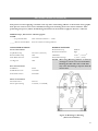
Image Image® 600 MD Laminator ® 6500 Owner’s Operation Manual Image ® 600 MD Laminator English All rights reserved All information included in this manual as well as information included in supplements or addendum to this manual is subject to copyright law. This information shall not be used, copied, reproduced, transmitted or disclosed to third parties without our prior written consent. SEAL Graphics assumes no responsibility for any errors that may appear in this document nor does it make expressed or implied warranty of any kind with regard to this material, including, but not limited to, the implied warranties of merchantability and fitness for a particular purpose. Seal Graphics shall not be liable for incidental or consequential damages in connection with, or arising out of the furnishing, performance, or use of this document and the program material which it describes. Français Tous droits réservés. Toutes les informations contenues dans ce manuel ainsi que celles des suppléments ou ajouts à ce manuel sont soumis aux lois sur le copyright. Ces informations ne doivent pas être utilisées, copiées, reproduites, transmises ou divulguées à des tiers dans notre autorisation préalable par écrit. SEAL Graphics n'accepte aucune responsabilité pour toute erreur pouvant apparaître dans ce document et ne donne aucune garantie tacite ou expresse eu égard à ce matériel, y compris mais sans s'y limiter, à toute garantie tacite de qualité marchande ou d'adaptabilité à un usage particulier. SEAL Graphics n'est pas responsable des dommages accessoires ou indirectes liés à ou découlant de la diffusion, performance ou l'utilisation de ce document et du matériel décrit. Deutsch Alle Rechte vorbehalten. Alle Informationen in diesem Handbuch sowie Informationen in Ergänzungen oder Zusätzen zu diesem Handbuch unterliegen dem Urheberrechtsgesetz. Die Informationen dürfen ohne unsere Genehmigung nicht verwendet, kopiert, wiedergegeben, übertragen oder an Dritte weitergegeben werden. SEAL Graphics haftet nicht für Fehler, die in diesem Dokument auftreten können, noch übernimmt SEAL Graphics Europe BV keinerlei ausdrückliche oder implizite Garantie in Bezug auf dieses Material, einschließlich, jedoch nicht begrenzt auf die implizierte Garantie der Marktgängigkeit und Eignung für einen bestimmten Zweck. SEAL Graphics haftet nicht für auftretende oder Folgeschäden in Verbindung mit oder entstehend aus der Ausstattung, Leistung oder Benutzung dieses Dokuments und des Programmmaterials, das es beschreibt. Español Reservados todos los derechos. Toda la información incluida en este manual y en los suplementos a anexos de este manual están sujetas a las leyes de derechos de autor. Queda prohibida la utilización, copia, reproducción, transmisión o divulgación de esta información a terceros sin nuestro consentimiento previo por escrito. SEAL Graphics no se hace responsable de los errores que pudieran aparecer en este documento ni tampoco ofrece garantía implícita o explícita de ningún tipo en relación con el material descrito, incluyendo, aunque sin que ello constituya un límite, las garantías implícitas de comercialización e idoneidad para una finalidad concreta. SEAL Graphics no responderá de los daños imprevistos o emergentes relacionados con, o que puedan surgir del suministro, funcionamiento o el uso de este documento y del material de programa que describe. Italiano Tutti i diritti riservati. Tutte le informazioni di questo manuale, nonché quelle dei supplementi o integrazioni a questo manuale sono soggette ai diritti d'autore (copyright) Queste informazioni non possono essere usate, copiate, riprodotte, trasmesse o comunicate a terze parti senza il nostro previo consenso scritto. SEAL Graphics Europa BV non si assume alcuna responsabilità per eventuali errori che possono comparire nel presente documento, né offre garanzia esplicita o implicita di alcun tipo in relazione a detto materiale, comprese, ma non limitatamente a, garanzie implicite di commerciabilità e adeguatezza per un particolare scopo. SEAL Graphics Europa BV non sarà responsabile per danni accidentali o indiretti relativi a, o derivanti dalla fornitura, dalle prestazioni, o dall'utilizzo del documento e dal materiale relativo al programma descritti. Seal Graphics Europe 2004, 2005 Seal Graphics Europe B.V., the Netherlands. P.O.Box 29 8100AA Raalte The Netherlands Tel.: 0031 572 346 000 Fax: 0031 572 346 001 TABLE OF CONTENTS TABLE OF CONTENTS--------------------------------------------------------------------------------------------------- 2 INTRODUCTION ---------------------------------------------------------------------------------------------------------- 3 WORKSPACE / CONNECTING THE LAMINATOR.................................................................................................4 UNPACKING, SET-UP AND INSTALLATION.............................................................................................................5 IMPORTANT SAFEGUARDS--------------------------------------------------------------------------------------------- 7 PRODUCT FEATURES ---------------------------------------------------------------------------------------------------- 9 SAFETY FEATURES................................................................................................................................................................9 LAMINATOR FEATURES.................................................................................................................................................. 10 FRONT CONTROL PANEL SYSTEM ............................................................................................................................ 11 PULL ROLLER CONTROLS.............................................................................................................................................. 12 PULL ROLLER PRESSURE CONTROLS....................................................................................................................... 13 TOP MOTOR CONTROL PANEL................................................................................................................................... 14 SET-UP AND OPERATION----------------------------------------------------------------------------------------------15 PRESTART CHECKS ............................................................................................................................................................ 15 BASIC OPERATING PROCEDURES.............................................................................................................................. 16 LOADING ROLLS OF MAT ERIAL................................................................................................................................. 17 TABLE OPERATION........................................................................................................................................................... 19 UNWIND BRAKE / COOLING SYSTEM OPERATION........................................................................................ 20 AUTO-RUN / FOOTSWITCH OPERATION............................................................................................................... 21 FEEDING IMAGES--------------------------------------------------------------------------------------------------------22 WEBBING FILMS WITHOUT A RELEASE LINER.................................................................................................. 23 WEBBING FILMS WITH A RELEASE LINER............................................................................................................ 24 DECALING (HEAT-ACTIVATED).................................................................................................................................. 25 DECALING (PRESSURE-SENSITIVE)........................................................................................................................... 26 MOUNTING............................................................................................................................................................................ 27 ENCAPSULATING................................................................................................................................................................ 28 PRE-COATING BOARDS................................................................................................................................................... 29 LOW-TEMP VINYL TRANSFER...................................................................................................................................... 30 PROCESS CONTROL SHEET-------------------------------------------------------------------------------------------31 CLEANING / MAINTAINING YOUR LAMINATOR---------------------------------------------------------------32 PERIODIC MAINTENANCE SHEET ---------------------------------------------------------------------------------33 TROUBLE SHOOTING GUIDE ----------------------------------------------------------------------------------------34 ERROR CODES ------------------------------------------------------------------------------------------------------------35 GLOSSARY OF TERMS---------------------------------------------------------------------------------------------------37 SPARE PARTS LIST -------------------------------------------------------------------------------------------------------38 TECHNICAL SPECIFICATIONS ---------------------------------------------------------------------------------------39 NOTES-----------------------------------------------------------------------------------------------------------------------41 NOTES-----------------------------------------------------------------------------------------------------------------------42 LIMITED WARRANTY ---------------------------------------------------------------------------------------------------43 2 INTRODUCTION Thank you for purchasing the Image® 600 MD Laminator. The Image 600 MD has been designed to provide you with years of reliable service. As you become familiar with the laminator, you will appreciate the high quality of production and the excellence in its engineering design. The Image 600 MD is a bi-directional laminator designed for full range, high volume requirements. This includes heat or pressure sensitive lamination, encapsulation and hot or cold mounting of images. Two sets of bidirectional rollers speed production, running heatactivated materials from the front and cold pressuresensitive applications from the back. Following the guidelines for proper care and use of the Image 600 MD, you can depend on many years of trouble-free profitability from your investment. The purpose of this manual is to describe installation, operation and maintenace of your laminator to create signs, displays, and flexible graphics with professional results. This manual includes instructions of various laminating procedures, which are provided to give you comprehensive information needed for the efficient and effective use of your laminator. Please read and fully understand the entire manual before using your laminator. STATEMENT OF INTENDED USE Your Image 600 MD Laminator is ETL/UL approved and meets all relevent CE Safety Directives.The Image 600 MD laminator has been designed to be used with SEAL Brand materials. When used with these products, you are able to mount, mount and laminate, and encapsulate prints in one step. Your laminator has been tested with SEAL Brand supplies and we recommend using these products for professional results. WARNING: This laminator is designed for mounting and laminating. Any use for purposes other than that for which the machine was designed may cause damage to the laminator or physical harm to the user. WARNING: Any unauthorized changes or modifications to this unit without prior written approval will void the user’s warranty and will transfer health and safety obligations to the user. LIABILITY STATEMENT Details provided in this manual are based on the most current information available. These details may be subject to change in the future. SEAL Graphics retains the right to make changes to the construction or design of our products without accepting any responsibility for modifying earlier versions previously delivered. CAUTION: Pay attention to all passages marked this way. This information is vital to preventing user injury and/or damage to the unit. Failure to follow this information could void the user’s warranties and transfer all safety obligations to the user. 3 W O R K S P A C E / C O N N E C T IN G T H E L A M I N A T O R CONNECTING THE LAMINATOR Connect the laminator in accordance with details as listed on the identification plate attached to the rear of the laminator. Refer also to the Technical Specifications page for additional information. CAUTION: SEAL Graphics recommends installation of a Ground Fault Interrupter (GFI) circuit breaker if operating the laminator near water or in an area of high humidity. 61" /15 5c m 5 cm /15 61" cm 15" / 38 cm t haf dS win Un Un win dS haf t a edi fM lls o Ro Minimum Room Width =15 feet/4.5 meter 38 15"/ SEAL Graphics recommends that a licensed electrician, in accordance with electrical codes in your area, install your main power or the warranty will be void. Specifications subject to change without notice. Rol ls o fM edia WORKSPACE Keep the area around your laminator clear with adequate space around it so you can feed, receive and trim mounted and/or laminated images. We recommend a room size of 20 ft.x 18 ft. (6.1 M x 5.49 M) to accommodate a laminator and two 4 ft. x 8 ft.(1.22 M x 1.44 M) tables on castors for finishing and/or layout work. This area is required for loading and unloading rolls of material onto the unwind shafts, and feeding and receiving the maximum mounting board lengths into the laminator correctly. NOTE: Maximum board lengths are up to 10 ft. (3.5 M) long. Work area should be level, flat, and well lit. Maximum board length Maximum board length 54"/137 cm Room Length = 2 x max. board length + 54" (137 cm) Minimum Room Length = 15 feet / 4.5 meter Figure 1: Workspace Area Diagram 4 UNPACKING, SET-UP AND INSTALLATION Only skilled personnel should perform installation. Read and comply with all warnings and follow the proper installation procedures and safety guidelines. Refer to the outside of the crate for Uncrating and Recrating instructions. Take into account the weight of the laminator (1850lb./839 kg shipping weight) when moving. Use equipment that can safely lift the weight. The laminator is shipped on a wooden pallet (skid). While the laminator is still on the skid, it may be moved using a forklift to position it near its place of use. CAUTION: Set the forks of the forklift to the maximum lifting width of the laminator, so the laminator’s center of gravity is central between the forks. CAUTION: Do not lift the laminator with a forklift once it has been removed from its skid. Doing so may damage the unit and void the warranty. NOTE: We recommend that you save the transport bolts, nuts and plates of the shipping crate for any major moves that you plan to make with the laminator in the future. Remove the cardboard boxes containing the tables and set aside. Remove the transport bolts from the skid’s transport plates using an open-end or adjustable wrench. Using the wrench, back the bolt up enough to clear the cabinet castors for ease in moving. Your laminator has castors to allow for easy movement. Roll the laminator to the location it will be used. (See Workspace Area Diagram – Figure 1). Lock the castors once it is in place. Remember to unlock them before moving the laminator again. Figure 2: Moving the laminator with a forklift. Accessories Included: • Grease Gun Kit • Spare Fuses (Inside Cabinet) • Tape Measure • Snitty Safety Knife • Image Roll Cleaner • Roll Cleaning Towel • Spare Core for Wind-up Shafts • Owner’s Manual • Installation Instruction Sheet • Quick Connect Coupler (supplied with all laminators) Available Options: • Leveling Feet • Auto-Grip Wind-up Idler 5 UNPACKING THE LAMINATOR 1. Remove the transport packing and the plastic shrinkwrap that the laminator is wrapped in to avoid moisture penetration during shipping. 2. Remove the accessory kit package from the top of the laminator. This kit includes the tools necessary for installation. 3. Remove the two footswitches from the top of the laminator. Remove the foam wrapped around them. 4. Place the footswitches in positions that are readily accessible while feeding images. 5. Remove the lower table bumpers using allen wrench provided. Lift and lock table in the upright position. Reinstall the lower table bumpers. 6. Remove the air tube, secured to the upper unwind shaft and its protective wrapping. 7. Insert the air tube in the lower position and position the magnetic fan opening cover (included in the accessory kit) over the top opening. 8. Cut and remove the tie straps securing the Unwind Shafts. 9. The Quick Connect Coupler (included in the accessory kit) can be used to connect to your air compressor. CAUTION: The top roller goes up automatically when air is connected. 10. Remove the foam placed between the top and bottom rollers. WARNING: Do not use open blades to remove the protective paper on the rollers. 11. Remove the stickers securing the protective paper on the rollers using fingers only. 12. Gently pull the paper towards you to unwind off the rollers. CAUTION: Roller damage caused by improper use of cutting tools will void the user’s warranty. Small cuts and imperfections in the rollers greatly affect the quality of the output and roller replacement costs are expensive. 6 LEVELING FEET OPTION A non-standard set of Leveling Feet are available as an option. The following procedure describes leveling procedures to be followed if your machine is equipped with this feature. 1. Thread the optional leveling feet (which if purchased are included in the accessory pack) onto each of the four transport bolts located in the corners of the cabinets. Tighten securely. 2. Use the ½ in. wrench to turn the transport bolts down until the leveling feet are positioned flat against the floor. 3. Insert a 3 ft. x 1 ft. (91cm x 30cm) piece of foam board across the two center chill idlers and place the level in the center on top of this foam board. 4. Adjust the leveling feet for each side cabinet until level. 5. Next, place the level on the tops of each of the cabinets lengthwise and adjust the leveling feet from the front to the rear of the cabinet as needed. IMPORTANT SAFEGUARDS AFTER SWITCHING OFF THE LAMINATOR, THE ROLLERS MAY REMAIN HOT FOR AND ADDITIONAL FOUR OR MORE HOURS. LAMINATOR SAFETY SYMBOLS CAUTION: Read and make sure you understand these safety and operating guidelines. Rotating Parts: Risk Of Injury Electrical Parts – Danger of being injured by electricity DANGER: DANGER: FAILURE TO USE CAUTION NEAR ROTATING PARTS, SUCH AS ROLLERS, COULD RESULT IN PHYSICAL INJURY. BE CAREFUL THAT ITEMS SUCH AS LOOSE CLOTHING, LONG HAIR AND JEWELRY DO NOT BECOME ENTANGLED IN ROTATING PARTS. The laminator is equipped with photoelectric eyes to prevent contact with the rotating rollers. Make sure that these safety provisions are installed and functioning properly prior to operation of the laminator. NOTE: The laminator operation will cease immediately when the photo electric eyes, set directly in the path of the front of the rollers, are blocked. The foot switch overrides the photo-electric eyes. When the photo eye is blocked, a BUZZER sounds, warning of close proximity to the nip. Use care to keep hands clear of the rollers while using the foot switch to prevent possible injury. Hot Surface: Risk Of Injury On Contact DANGER: BOTH THE TOP AND BOTTOM ROLLERS OF THE LAMINATOR ARE HEATED. ROLLERS MAY REACH TEMPERATURES OF 275°F (135°C). THERE IS A BURN DANGER IF EITHER OF THE HEATED ROLLERS ARE TOUCHED DURING USE. EVEN DO NOT REMOVE THE FASTENED CABINET DOORS BECAUSE OF THE RISK OF BEING INJURED BY VOLTAGE. ONLY AUTHORIZED MAINTENANCE AND SERVICE TECHNICIANS OR SAFETY PERSONNEL SHOULD REMOVE THE DOORS IF MECHANICAL UPKEEP OR REPAIR IS REQUIRED. DOORS MUST BE REPLACED IMMEDIATELY UPON COMPLETION OF UPKEEP OR REPAIRS. DANGER: MAKE SURE THE CIRCUIT BREAKERS ON THE REAR OF THE LEFT SIDE CABINET ARE IN THE OFF POSITION (FLIPPED DOWN) BEFORE REMOVING THE CABINET DOORS FOR ANY MAINTENANCE. NOTE: Do not place heavy objects on the power supply cord. PREVENTATIVE MEASURES: Do not feed objects such as staples, paper clips and rough or abrasive materials through the laminating rollers. Keep all objects, such as tools, rulers, pens, markers or knives away from the roller opening. Refrain from leaving such items on the tables to prevent them from accidentally being fed into the rollers. CAUTION: NEVER cut or slice directly on the rollers as any cuts or gouges will destroy them. ALWAYS use cutters with enclosed blades to prevent cutting 7 the rollers and to avoid extensive replacement costs. WARNING: When the laminator is not in use, adjust the shim wheels to create a gap between the laminating rollers to prevent flat spots from developing. Flat spots would affect the quality of the output and void the warranty replacement. CAUTION: Static Shock Risk – Because under certain contions, the unrolling films can cause a build up of static electricity, the operator is cautioned to be aware of this and take appropriate safeguards to prevent static shock. CAUTION: The main rollers should be together and turning while heating up to prevent uneven hot spots on the roller. Stationary rollers will develop concentrated heat in one area, which will damage the roller. Pivot the front table away from the heated roller when not in use to prevent possible warping. SERVICING AND REPLACEMENT PARTS Service and maintenance must be performed fully in accordance with the provided instructions. Servicing by any unauthorized technician voids the warranty. Service technicians must use replacement parts as specified by SEAL Graphics. CAUTION: 8 Service Technicians must perform safety checks after completing any service or repairs to the laminator. PRODUCT FEATURES SAFETY FEATURES The Image® 600 MD Laminator is designed with safety and protective devices with the user’s safety the primary consideration. However, following safe operating guidelines is still the responsibility of the user. Hand-Operated Emergency Stop Buttons Emergency Stop buttons are located on each side of both cabinets for easy access. When pressed, they immediately suspend laminator operations, and raise the rollers. CAUTION: As use of the emergency Stop pushbuttons in effect “suspends” active operations, their primary purpose is for use in an emergency situations only. Do not use the Emergency Stop switches as part of your normal operating procedure, or you may damage an image during processing. NOTE: Once pressed, Emergency Stop buttons lock. To disengage, they must be turned clockwise to reset. After resetting the Emergency Stop button, you must turn the heaters back on (if being used), and push one of the Motor Direction Switches to begin processing again. Cabinet Doors / Circuit Breaker Access The cabinets that house the inner workings of the laminator have fastened cabinet doors and an outside access circuit breaker that is located on the rear of the left cabinet as viewed from the front. Only maintenance or safety personnel should open the doors after turning off the main circuit breakers for maintenance upkeep or repair. DANGER: FOR ANY SERVICING, ALWAYS TURN THE MAIN POWER CIRCUIT BREAKERS OFF BEFORE OPENING THE SIDE CABINETS WARNING: Use of the inside of the cabinets for storage may lead to personal injury and/or damage to the inner workings, and will void the warranty Photo Electric Safety Eyes A photo electric light beam path is set directly in front of and back of the laminating roller openings, preventing foreign objects from passing between the rollers. (These eyes are set for use at the factory and checked by the service representative.) WARNING: The laminator operation will cease immediately when the photo electric eyes, set directly in the path of the front of the rollers, are blocked. Covered Foot Switches The two foot switches allow for complete user control when initially feeding an image into the nip, or when feeding a delicate image through the rollers. The foot switch covers prevent accidentally stepping on a foot switch and starting the laminator. The foot switches override the photoelectric eyes. When the photo eye is blocked, a BUZZER sounds, warning of close proximity to the nip, and the laminator runs in slow mode at a speed of 2.0 ft (0.6 M) per minute. Use care to keep hands clear of the rollers while using the foot switch to prevent possible injury. 9 LAMINATOR FEATURES 6 4 5 3 2 3 7 1 8 5 9 Figure 3: Laminator Features STANDARD FEATURES 1 - Control Panel System For independent control of pressure, temperature, cooling system and read-out of speed and material usage. 2 - Top Motor Control Panel Controls in-feed direction and processing speed. 3 - Shim Wheels (4) Dial-in roller height adjustment for fast and accurate roller nip setting, which adjusts for the thickness of the material to be processed 4 - Integral Braking System A simple braking system with a knurled collar provides the means of adjusting the brake tension for the films and images. Fitted on both roll easel shaft and the two unwind shafts. 5 - Swing-Out Autogrip Unwind Shafts (2) Easy loading and positioning of materials. No need for manual locking keys. Suitable for rolls wound onto a 3? ID core. 6 - Autogrip Wind-up Idlers (3) Removable shafts for winding up the release liner, finished images or other laminate material. Use with 3? ID spare cores. 7 - Emergency Stop Buttons (4) Immediately ceases the laminator’s operation and raises the rollers. 10 8 - In-feed Tables (2) Front and rear table with image guide for flat, wrinkle-free feeding of digital prints 9 - Covered Foot Switches (2) Allows for user control of roller speed when feeding in images. See Footswitch Operation for additional information. SPECIAL FEATURES ** Bi-Directional Operation Eliminates the need for cool-down allowing quick application changeovers. ** Dual-Position Cooling Tube Offers quick and uniform cooling for smooth, flat output during heat-activated processes. Can be positioned above or below the chill idlers and can be rotated to direct airflow as desired. ** Drive System Heavy-duty Clutch and simplified drive system – Provides smoother performance at all speeds and different film thickness. ** Heating Elements Electric High-Wattage Heating Elements and Temperature Controls with Infrared Temperature Sensors – Provide for rapid, even heating to 275° F (135°C) and maximum accuracy. FRONT CONTROL PANEL SYSTEM 1. Air Pressure Gauge: Indicates the PSI reading for the downward pressure of the top main roller. The standard setting for the normal operation is 35-55 PSI. 2. Air Regulator Knob: Adjusts the downward pressure of the top roller. Turn clockwise to increase the pressure. 3. Roller Up/Down Switch (Front, Top): Press up to raise the roller. Press down to lower the roller. 4. Cooling Fan On/Off Button: Turns On/Off the cooling fan. The corresponding LED will be lit when the fan is ON. 5. Reset Button: Press this button to reset the material total usage counter to zero. Totalizer Display must be showing to be able to zero out. 6. Ratemeter /Totalizer Button: Pressing this button will toggle between the roller speed readout or total material usage. Press this button to track and display the total number of feet or meters run in a given period, which can help to monitor film usage. The total will be stored even after the laminator is turned off, and adds to the total whenever the bottom main roller is turning. The corresponding LED will be lit when the totalizer is being used. 7. Ratemeter/Totalizer Readout: Displays the rate of speed of the main rollers in either feet or meters per minute, or displays the total number of feet or meters run in a given period. 8. Top Roller Temperature Increase Button: Press this button once to view the temperature set point. Press and hold the button to raise the top roller temperature. 9. Top Roller Temperature Readout: Displays both the set and actual temperature of the top roller. 10. Top Roller Temperature Decrease Button: Press this button once to view the temperature set point. Press and hold the button to lower the top roller temperature. 11. Bottom Roller Temperature Increase Button: Press this button once to view the temperature set point. Press and hold the button to raise the bottom roller temperature. 12. Bottom Roller Temperature Readout: Displays both the set and actual temperature of the bottom roller. 13. Bottom Roller Temperature Decrease Button: Press this button once to view the temperature set point. Press and hold the button to lower the bottom roller temperature. 14. Bottom Roller Temperature On/Off Button: Turns On/Off the bottom roller heater. The corresponding LED will be lit when the heater is ON. 15. Top Roller Temperature On/Off Button: Turns On/Off the top roller heater. The corresponding LED will be lit when the heater is ON. 16. Stand-by On/Off Switch: Press this switch up to turn on the laminator. Press this switch down to put it on Standby. In Standby, the laminator power is still on, but all functions are disabled. 1 6 2 4 2 0 8 1 1 1 1 3 4 5 6 7 8 9 10 11 12 13 14 15 16 Figure 4: Front Control Panel System 11 PULL ROLLER CONTROLS The Pull Roller controls are located on the right side cabinet when facing the rear of the laminator. 1. Air Regulator Knob: Adjusts the downward pressure of the top pull roller. Turn clockwise to increase the pressure. 2. Air Pressure Gauge: Indicates the PSI reading for the downward pressure of the top pull roller. The standard setting for the normal operation is 35-55 PSI. 3. Roller Up/Down Switch (Rear, Top): Press the switch up to raise the roller. Press the switch down to lower the roller. 12 1 2 3 6 4 2 0 8 1 1 1 1 Figure 5: Pull Roller Controls PULL ROLLER PRESSURE CONTROLS 60 40 1 80 20 0 10 12 2 14 16 Figure 6: Pull Roller Pressure Controls The Pull Roller Pressure Control Panel is located on the left side cabinet when facing the rear of the laminator. The operator can adjust the amount of tension that is directly applied to the laminate between the main and pull rollers. The amount of tension applied affects the output and extreme pull tension will stretch the hot films causing outfeed waves in the finished product. This is a factor with films such as Print Guard®, which stretches easily. Excessive tension will also cause downward curl in the finished product. The standard setting for normal operation is 40-60 PSI. 1. AIR REGULATOR KNOB This knob adjusts the pulling tension of the bottom pull roller. Turn clockwise to increase the amount of pull tension and turn counter-clockwise to decrease the amount. 2. AIR PRESSURE GAUGE Indicates the PSI reading for the pulling tension of the bottom pull roller. The standard setting for normal operation is 40-60 PSI. CAUTION: Excessive pull clutch tension will cause premature wear to the drive system and may cause damage to the laminator. Use the minimum amount required for the laminating process. 13 TOP MOTOR CONTROL PANEL 1 2 4 3 Figure 7: Top Motor Control Panel MOTOR CONTROL PANEL OPERATION 1. Speed Adjustment Knob Use this knob to adjust the speed of the roller rotation. Turn the knob clockwise to increase the speed of the roller rotation and counter-clockwise to decrease its speed. The speed of the rollers is continuously adjustable between 0 and 15 ft /min. (0 and 4.6M/min.). Roller speed can be viewed in the top display readout on the front control panel. 2. Reverse Roller Direction Switch Pressing the Motor Stop Switch and this switch will cause the rollers to rotate in the reverse direction when standing at the front of the laminator. This direction will be used when processing cold pressure-sensitive films from the rear of the laminator through the pull rollers. 3. Motor Stop Switch Pressing this switch stops roller rotation. NOTE: Whenever the rollers are rotating, you must press this switch prior to changing roller direction. 4. Forward Roller Direction Switch Pressing the Motor Stop Switch and this switch will cause the rollers to rotate in the forward direction when standing at the front of the laminator. 14 SET-UP AND OPERATION After you have reviewed the operational details provided and prior to operations check all controls to become familiar with their operation and function. PRESTART CHECKS CHECK THE MAIN POWER 1. Position the Stand-by Power Switch in the up position and verify that the front displays on the control panel light up. 2. The center red switch on the top cabinet control panel should be illuminated. CHECK THE EMERGENCY STOP BUTTONS 1. Press one of the Emergency Stop Buttons and the laminator should stop operation. 2. Rotate the Emergency Stop Button clockwise to reset. 3. Repeat this procedure with all four Emergency Stop Buttons. CHECK THE HEATER CONTROLS 1. Press the Top Heater On/Off button once; the corresponding LED should be lit. 2. The readout will display the ambient temperature. 3. Press and hold the top heater Up Arrow to increase the temperature set point. Watch the readout for 5 minutes to verify that the temperature increases. 4. Press and hold the Down Arrow to decrease the temperature set point. 5. Press the top heater On/Off button again once; the corresponding LED should not be lit. 6. Repeat this procedure for the Bottom Heater. 5. Turning the speed control knob counter-clockwise should decrease the speed of the rollers and the speed readouts should decrease in number. 6. Press the footswitch and the rollers should rotate in whichever roller direction that was last pressed at a speed of 2.0 ft (0.6 M) per minute. Check both footswitches for operation. CHECKING THE ROLLERS Your laminator has pneumatic pressure adjustment with fine-tune control for a smooth, flat finish. Correct adjustment of the pressure rollers’ height is essential for safe and proper operation. Check this prior to every use. Check the vertical movement of the top rollers as follows: 1. Press the Roller switch UP. The top roller should rise smoothly and evenly on both ends. 2. Press the Roller switch DOWN. The top roller should lower smoothly and evenly on both ends. 3. Repeat this procedure for both front and rear top rollers. CAUTION: The silicone covering of the rollers is soft. Do not scratch the surface with a sharp object or fingernail. WARNING: If your laminator does not operate correctly, contact Technical Service immediately. CHECK THE MOTOR AND FOOTSWITCH 1. Push the green Motor Forward Switch and the rollers should rotate in the forward direction. 2. Press the center red Motor Stop Switch and the rollers should stop rotating. 3. Press the green Motor Reverse Switch and the rollers should rotate in the reverse direction. 4. As you turn the speed control knob clockwise the speed of the rollers should increase and the speed readout (top display on front control panel) should increase in number. 15 BASIC OPERATING PROCEDURES WARNING: Too much pressure can crush the board being used and even damage the top and bottom rollers. Normally, a press of .025 in. (0.6mm) is sufficient. / 19 3 SHIM WHEEL SETTINGS Whenever you mount onto a board, etc., it is important to adjust the rollers to create a gap nearly equal to the thickness of the board being used. This is done so that anything passing between the rollers will receive the right amount of pressure. HOW TO SET THE SHIM WHEELS Determine the thickness of the board being used for mounting. Raise the rollers and then turn the shim wheels until the desired measurement corresponds with the thickness of board being used. m m 4 in m m i 5 /1 6 3 n TEMPERATURE SETTINGS Select the film(s) that you will use on the top (and bottom) of the images. Check the recommended temperature setting for the material(s) selected (see literature enclosed in your material box). NOTE: If a process requires heat, turn ON the heaters 45 minutes before use to ensure rollers are correct operating temperature. Refer to the Front Control Panel Diagram for information on setting the temperature. CAUTION: The main roller should be down and turning to prevent uneven hot spots on the roller. A stationary heated roller will develop concentrated heat in one area, which will damage the roller. 25 1 mm in - 2m m - 1 /16 in 0 2mm 1/16 in m 3 m in 1/8 Equivalent Press Measurements 16 Inches Metric (mm) Decimal 1 3/4 1/2 3/8 1/4 3/16 1/8 1/16 -1/16 0 25 mm 19 mm 13 mm 10 mm 6 mm 5 mm 3 mm 2 mm -2 mm 0 1.000 0.75 0.50 0.375 0.25 0.1825 0.125 0.0625 -0.0625 0 Figure 8: Shim Wheel Adjustment LOADING ROLLS OF MATERIAL LOADING A ROLL OF MATERIAL Turn the unwind brake fully towards you so there is no brake tension on the unwind shaft- (until no gap is visible between the unwind brake knurled collar and the retaining ring). Swing out the desired unwind shaft towards you and slide a roll of material onto the unwind shaft. Ensure that the rubber blocking cords are on the top and bottom of the shaft for easy loading (see below). Figure 9: Loading Roll of Material NOTE: Make certain that you place the roll of film on the unwind shaft so that the material will feed with the adhesive side facing away from the rollers. NOTE: Make sure to align the notch in the end of the unwind shafts with the ball plunger of the cabinets to prevent tension and tracking problems. CAUTION: If the end of the shaft is not correctly aligned you will not be able to adjust the brake tension properly, causing tracking problems. For the bottom unwind shaft flip the hinged upper brace upwards (Figure 10, Item 1) so the shaft can be pulled out and loaded with material. 1 Figure 10: Locking Receiver Remember to flip the hinged brace back down onto the bottom unwind shaft so the film tracks correctly and the unwind shaft does not pull out of alignment. Center the films on the unwind shafts using the rulers on the unwind shafts for alignment. NOTE: The position of all films, boards, rolls of media and cardboard cores for wind-ups must be set central in the laminator to ensure optimum quality and correct tracking. For alignment accuracy, pull a length of film forward off the top unwind shaft until it drapes over the film on the bottom unwind shaft. Make sure the edges of both film rolls line up. Now secure the rolls of material onto the shafts by gripping the shafts with one hand while rotating the rolls of material with the other hand in the direction it will be pulled off the unwind shafts. The rubber blocking cords will catch on the inside of the material core and hold the material secure on the shaft. If material needs to be rotated, turn the shafts, not the rolls of film otherwise the roll of film will no longer be secured to the shaft. 17 UNWIND SHAFT CORD ADJUSTMENT Over time the rubber blocking cords will stretch and need to be shortened slightly. To adjust the cord, 1. Unfasten the cord at one end 2. Cut off 0.39 in. (1 cm). 3. Refasten the cord under the cord retainer clip. 18 TABLE OPERATION PIVOTING TABLE USE FOR WEBBING To facilitate webbing, remove the top wind-up idler and set it aside. 1 Figure 11: Table Release Handle Grasp and pull the table release handle located UNDER the center of the table (Figure 11, Item 1) which pulls the table plungers towards the center of the table. Pivot the table down, away from the rollers (Figure 12). Figure 12: Pivoting Table Down Reach through the opening between the table and rollers and pull the bottom film up and pass it behind the bottom idler. Pull the film up and place it over the top roller. Reposition the table by lifting the outer edge upwards and pivot in towards the roller (Figure 13). Figure 13: Table Pivoting Up Grasp and pull the table release handle, lift and rotate the table in the level postion. Release the handle allowing the plungers (Figure 14, Item 1) to seat in locked position, securing the table in the normal operating position. 1 Lock Figure 14: Locking Table Into Position When seated, the plungers hold the table in the horizontal position by locking into the main frame, both left and right, of the 600 MD. (See Figure 14) NOTE: Table operation is the same for both the front and rear tables. 19 U N W I N D B R A K E / C O O L IN G S Y S T E M O P E R A T I O N SETTING THE UNWIND BRAKE TENSION NOTE: The brake tension greatly affects the smooth flow of the laminating film. Adjust the unwind brake (Figure 15, Item 2) so that it applies sufficient tension to the laminate. 2 Figure 16: Inserting Cooling Tube To remove the cooling tube from the bottom location: 1. Press the cooling tube towards the left cabinet, compressing the spring to clear the cabinet opening. 2. Lift upwards at an angle and pull the tube up through the center of the chill idlers. Figure 15: Unwind Brake 1. Turning the unwind brake in a counter-clockwise direction increases the braking tension applied on the laminate. 2. Turning the unwind brake in a clockwise direction decreases the braking tension. Generally, the least amount of tension produces the fewest film wrinkles. The best setting for the unwind brake tension is determined by the materials you are using and is generally learned through experience. COOLING SYSTEM The Image 600 MD has a dual position cooling tube, which can be placed above or below the center chill idlers to cool heat-activated materials. During most operations the cooling tube will be used in the position below the chill idlers. However, it can also be used in the position above the chill idlers to assist with cooling down the top main roller. To improve cooling in this configuration, pivot the airflow holes towards the top main roller. 20 To insert the cooling tube in the top location: Reverse the above procedures to change from the top location to the bottom location. Remember to replace the magnetic tube opening cover over the lower cooling opening. The cooling tube can also be rotated to direct the airflow as needed. The majority of processes do not require the use of the cooling tube, but for extensive running time, it is recommended to use the cooling tube to cool off the chill idlers quicker. Pivot the cooling tube airflow holes towards the front idler, which receives the most heat from the heated main roller. Always web the film over the first idler to cool the backside of the print first, thus preventing marks on the hot front side of the print, which could affect the finished appearance. When using Mounting Adhesive on the back of images it is best to run the film over both idlers. Running the film under the second idler may cause the backing to separate from the release liner. A U T O - R U N / F O O T S W I T CH O P E R A T I O N AUTO-RUN OPERATION The continuous-run operation allows the user to set the direction of the roller rotation and adjust the roller speed by turning the Speed Control knob on the top of the left side cabinet. This feature is useful for long runs that don’t require much user control, and when used with the rear wind-up shafts can be efficient in an auto-run mode. 1. Press the motor direction switch for the processing direction desired. 2. Turn the speed control knob on the Motor Control Panel to adjust the speed of the rollers (refer to the Top Motor Control Panel page). WARNING: While using the footswitch, interrupting the photoelectric safety eyes does NOT stop the laminator. An audible beep will be heard, the motor directional switch will be blinking and the roller speed will run in ‘slow mode’ at a speed of 2ft/min (0.6 m/min.). Releasing the foot switch will stop the laminator, unless the machine is in auto-run mode. 4. After clearing the photoelectric eye blockage the buzzer will stop. 5. To resume the pre-set speed, press the blinking directional switch. NOTE: If the photoelectric eyes become blocked during continuous-run operation, the roller rotation will stop immediately. (On Domestic laminators only). After clearing the photo-eye blockage, the motor will restart in slow-mode. Otherwise, the blinking directional switch will have to be pressed again to resume the pre-set speed. CHANGING FROM FOOTSWITCH OPERATION TO AUTO-RUN MODE WITHOUT STOPPING (This prevents stop marks on the substrate): During footswitch operation (keep the foot switch pressed), then press the Motor Direction switch desired on the Motor Control panel. The laminator will run at the preset speed. Next, release the foot switch. NOTE: Be very careful not to stop the motor or block the photo eyes while an image is being laminated, as this can cause marks in the output. NOTE: Do not stop the motor or block the photo eyes while an image is being laminated as this can cause marks in the output. FOOTSWITCH OPERATION The function of the footswitch is to permit the rotation of the rollers to be controlled in a hands-free manner. This feature can be used when webbing materials onto the laminator or feeding delicate images and overrides the photoelectric safety eyes. 1. Pressing the footswitch runs the laminator in the direction that was pressed last (the active directional switch will be illuminated). 2. The rollers will run at the speed last set which is indicated in the top display on the front control panel. 3. The speed can be adjusted when using the footswitch by turning the speed control knob on the top of the cabinet. Rotation of the rollers stops when: 1. The photoelectric eyes in the front or back of the rollers are interrupted. CAUTION: This does NOT happen when the foot switch is pressed. 2. An emergency stop button is pressed. 3. The stop button on the motor control panel is pressed and the operator is not using the footswitch. 21 FEEDING IMAGES BASIC STEPS TO FEEDING IMAGES 1. Make sure the leading edge of each image is flat all the way across or any wrinkles or creases in the image will show when laminated – perhaps even magnified. Feeding images under the print guide, directly into the nip, prevents the images from lifting up and interrupting the photo eyes. 2. A straight leading edge will aid in feeding in the image. 3. Feed the image into the laminator ensuring that the leading edge is parallel to the roller. NOTE: Do not stop the motor while an image is being finished as this can cause marks in the output. USING THE PRINT GUIDE TABLE Your laminator is designed with Print Guide Tables to assist in feeding images into the nip. Figure 18: Feeding Images under the print guide Figure 17: Print Guide Table 22 WEBBING FILMS WITHOUT A RELEASE LINER The following are the basic webbing procedures for webbing films without a release liner: 1. Select films slightly wider than the image to allow for a border without film waste. A border of 1/8 in. to ¼ in. (3 - 6 mm) is adequate. 2. Ensure the main roller’s temperatures are set according to the recommendations of the laminates being used (see literature enclosed in your material box). WARNING: The rollers should be down and turning while heating up to provide even heat distribution and prevent roller flat spots from developing. 3. Once the laminator reaches correct operating temperature, stop the laminator and raise the top roller. 4. Load and center the films on top and bottom unwind shafts with the dull adhesive side facing out and the Unwind Brake tension released. NOTE: Check if the film widths of the lower and upper web are the same! 5. TOP FILM: Pull the film down from the top unwind shaft, behind the top center idler and place it evenly over the face of the top roller. 6. Pivot the front table down for easier webbing access. 7. BOTTOM FILM: Pull the film up from the bottom unwind shaft, behind the bottom center idler and place it evenly over the top film draped over the face of the top roller. 8. The two films will then heat and stick together. 9. Set the Shim Wheels to 1/16 in. (2mm) to allow for the thickness of the leader-board. 10. Use a leader-board to push the film(s) through the main roller nip. 11. Lower the top roller and pivot the in-feed table into position. 12. Moving to the rear of the laminator, use the foot switch to advance the leader board. 13. Feed the leader-board over the first chill idler and under the second chill idler. NOTE: For top and bottom film combinations of 10 mil or less, feed over the first idler and under the second. For film combinations of 10 mil or over, feed over both chill idlers. 14. Raise the top pull roller and advance the leader board through the pull rollers. 15. Holding the leader board up against the top edge of the top pull roller lower the roller. Make sure the rear Shim Wheels are set to ‘0’ (0mm). 16. Return to the front of the laminator and set the front Shim Wheels to -1/16 in. (-2 mm). 17. Using the footswitch advance the films, applying light unwind brake tension gradually on both unwind shafts until there are no wrinkles in the film as it goes into the nip. You are now ready to feed images! Figure 19: Webbing films w/o Release Liners 23 WEBBING FILMS WITH A RELEASE LINER The following are basic webbing procedures for webbing films with a release liner: 1. Select films slightly wider than the image to allow for a border without film waste. A border of 1/8 in. to ¼ in. (3 – 6 mm) is adequate. 2. Load and center the films on top and bottom unwind shafts with the dull adhesive side facing out and the unwind brake tension released. NOTE: Check if the film widths of the lower and upper web are the same! 3. TOP FILM: (film with a release liner) Pull the film down from the top unwind shaft, behind the top center idler and place it evenly over the face of the top roller. 4. Place a spare core over the front top wind-up idler. Separate the film from the release liner. Attach the release liner to the spare core using a piece of tape. 5. Pivot the front table down for easier webbing access. 6. BOTTOM FILM: Pull the film up from the bottom unwind shaft, behind the bottom center idler and place it evenly over the top film draped across the face of the top roller. The two films will stick together. 7. Set the Shim Wheels to 1/16 in. (2 mm) to allow for the thickness of the leader-board. 8. Use a leader-board to push the film(s) through the nip. 9. Lower the top roller and pivot the in-feed table into position. 10. Moving to the rear of the laminator ,use the foot switch to advance the leader-board. 11. Feed the leader-board over the first chill idler and under the second chill idler. NOTE: For top and bottom film combinations of 10 mil or less, feed over the first idler and under the second. For film combinations of 10 mil or over, feed over both chill idlers. 12. Raise the top pull roller and advance the leader board through the pull rollers. 13. Holding the leader board up against the top edge of the top pull roller lower the roller. Make sure the rear Shim Wheels are set to ‘0’ (0mm). 14. Return to the front of the laminator and set the front Shim Wheels to –1/16 in. (-2 mm). 15. Using the footswitch advance the films, applying light unwind brake tension gradually on both unwind shafts 24 until there are no wrinkles in the film as it goes into the nip. You are now ready to feed images! Figure 20: Webbing for North America Figure 21: Webbing for Europe & Asia DECALING (HEAT - ACTIVAT ED) This process involves applying a hot film to the top and a cold backing adhesive to the bottom of the graphic. This process can be used to create self-adhesive images for mounting down onto various substrates. After performing this process, follow the Mounting Instructions in the manual to apply the decal to a substrate. MEDIA: Ink Jet, Electrostatic and Photographic FILMS: -- -- -- Top Unwind Shaft: Heat-activated Laminate 3 – 5 Mil _____ Bottom Unwind Shaft: Pressure-sensitive mounting adhesive LAMINATOR SETTINGS Front Control Panel Top Roller Temp Bottom Roller Temp Main Roller Pressure Cooling Fan: 205-215°F (96-102°C) OFF 35-40 PSI OFF Rear Control Panels Pull Rollers: Pull Roller Pressure Pull Clutch Tension Down 35-40 PSI 40-60 PSI Motor Control Panel Motor Direction: Motor Speed Setting Forward 3-5 FPM (1-1.5 MPM) WEBBING SETTINGS Web Tension Top: Medium Web Tension Bottom: Light Chill Idlers: Over 1st / Over 2nd: Shim Wheel Settings: -1/16 in. (-2 mm) NOTE: When using Mounting Adhesive on the back of images it is best to run over both idlers. Running the film under the second idler may cause the backing to separate from the release liner. Figure 22: Webbing for Decaling (Heat-activated films) 25 DECALING (PRESSURE-SENSITIVE) This process involves applying a cold pressure-sensitive over-laminate to the top and a cold pressure-sensitive mounting adhesive to the bottom of a graphic. This process can be used to create self-adhesive images for mounting down onto various substrates. After performing this process, follow the Mounting Instructions in the manual to apply the decal to a substrate. MEDIA: Ink Jet, Electrostatic, and Photographic FILMS: -- -- -- Top Unwind Shaft: ____ Bottom Unwind Shaft: Pressure-sensitive over-laminate Pressure-sensitive mounting adhesive LAMINATOR SETTINGS Front Control Panel Top Roller Temp: Bottom Roller Temp: Main Roller Pressure: Cooling Fan: OFF OFF 35-40 PSI OFF Rear Control Panels Pull Rollers: Pull Roller Pressure: Pull Clutch Tension: Down 35-40 PSI 40-60 PSI Motor Control Panel Motor Direction: Motor Speed Setting: Reverse 3-5 FPM (1-1.5 MPM) WEBBING SETTINGS Web Tension Top: Web Tension Bottom: Chill Idlers: Shim Wheel Settings: Light Light Over 1st / Over 2nd -1/16 in. (-2 mm) NOTE: When using Mounting Adhesive on the back of images it is best to run over both idlers. Running the film under the second idler may cause the backing to separate from the release liner. NOTE: Pressure-sensitive films, not requiring heat, can be run from the front or rear of the laminator. Figure 23: Webbing for Decaling (Pressure-sensitive films) 26 MOUNTING This process involves mounting previously prepared decals onto a substrate. No films or adhesives are required for this process. TO MOUNT DECALS ONTO A SUBSTRATE 1. Place the mounting board on a flat surface. 2. Lay your image face down on the mounting board and expose approximately 1 in. (25 mm) of the adhesive by peeling back the release liner along one of the edges. 3. Fold the release liner back making an even crease. 4. Turn the image over and carefully position the exposed adhesive edge of the image squarely onto the board. 5. Once positioned correctly, press the exposed adhesive edge of the image firmly down onto the board from the center toward the edges to ensure a smooth surface. This is the edge that will be fed into the rollers first. NOTE: Ensure that the Shim Wheel settings of the rollers correspond to the board thickness. 6. Push the edge of the board into the rollers and depress the foot switch until the board and image are just caught by the nip. 7. Flip the un-tacked portion of the image over the top roller with one hand so that the release liner can be peeled off the image with the other hand. 8. Depress the foot switch to feed the board through the rollers. CAUTION: Because the foot switch overrides the photo eye, be sure to keep your hands clear of the rollers to prevent injury. 9. At this point, continuous run can be selected by pressing the Forward Motor Direction switch. NOTE: Take care that the rollers do not grab the liner. 10. If the board is accidentally sent in too far at first, the release liner will get caught and it will be impossible to pull it back. In this case, stop and reverse the motor until the liner can be pulled away. 11. The image must be held against the roller while the board feeds through to prevent wrinkles. NOTE: Take care that the release liner does not trip the optical safety system. 12. As the process becomes more familiar, the speed of the laminator may be increased to make the process more efficient. 13. Remove the mounted image from the rear of the laminator, trim it to size and display it. Figure 24: Mounting decals onto substrates 27 ENCAPSULATING This process involves completely sealing an image between two films. MEDIA: Ink Jet, Electrostatic, and Photographic FILMS: -- -- -- Top Unwind Shaft: Heat-activated Laminate 3 – 5 Mil ____ Bottom Unwind Shaft: Heat-activated Laminate 3 – 5 Mil LAMINATOR SETTINGS Front Control Panel Top Roller Temp: 205-215°F (96-102°C) Bottom Roller Temp: Main Roller Pressure: Cooling Fan: 205-215°F (96-102°C) 35-40 PSI OFF WEBBING SETTINGS Web Tension Top: Web Tension Bottom: Chill Idlers: Shim Wheel Settings: Medium Medium Over 1 st / Under 2nd 0 NOTE: Follow the webbing instructions for films specific for your location. Rear Control Panels Pull Rollers: Pull Roller Pressure: Pull Clutch Tension: Down 35-40 PSI 40-60 PSI Motor Control Panel Motor Direction: Motor Speed Setting: Forward 3-5 FPM (1-1.5 MPM) Figure 25: Webbing for Encapsulating 28 PRE-COATING BOARDS This process is used to coat substrates with a self-adhesive coating onto which images can be mounted. FILMS: -- -- -- Top Unwind Shaft: ____ Bottom Unwind Shaft: Pressure-sensitive Mounting Adhesive Heat-activated Laminate 3-5 Mil (Optional) LAMINATOR SETTINGS Front Control Panel Top Roller Temp: 120°F (49°C) Bottom Roller Temp: Main Roller Pressure: Cooling Fan: Optional 35-40 PSI OFF Rear Control Panels Pull Rollers: Pull Roller Pressure: Pull Clutch Tension: Down 35-40 PSI 40-60 PSI Motor Control Panel Motor Direction: Motor Speed Setting: Forward 3-5 FPM (1-1.5 MPM) WEBBING PROCEDURE Load the roll of pressure sensitive adhesive with the exposed adhesive facing you. Do not wrap around the top idler. Use a leader-board of the same thickness as the boards to be coated. Press the foot switch and using the leader -board, push the adhesive into the roller nip. Release the foot switch when the rear edge of the leader-board is almost leaving the roller nip. Position the board to be coated into the nip, and choose a speed setting. NOTE: When coating boards, ensure that the next board to be coated follows the previous board without any gaps. NOTE: Follow the last board being coated with the leader-board again to allow the final board to clear the laminating rollers. Then stop the motor and raise the top roller. WEBBING SETTINGS Web Tension Top: Light Web Tension Bottom: Medium Chill Idlers: Over both Shim Wheel Settings: Substrate Dependent NOTE: Ensure that the Shim Wheel settings of the rollers correspond to the board thickness. NOTE: Adding a heat-activated laminate to the backside of the board will prevent the board from warping over an extended period of time. Figure 26: Pre-Coating Boards 29 LOW -TEMP VINYL TRANSFER This process involves transferring an image onto a flexible vinyl. Top roller temperature and amount of main roller downward pressure is dependent on the type of toners. Use the minimum amount of pressure required for successful transfer. MEDIA: Electrostatic FILMS: -- -- -- Top Unwind Shaft: ____ Bottom Unwind Shaft: Media with Toners Banner Vinyl LAMINATOR SETTINGS Front Control Panel Top Roller Temp: 250-275°F (121-135°C) Bottom Roller Temp: Main Roller Pressure: Cooling Fan: 140-150°F (60-65°C) 80-100 PSI ON (Under chill idlers) Rear Control Panels Pull Rollers: Pull Roller Pressure: Pull Clutch Tension: Down 40-60 PSI 40-60 PSI Motor Control Panel Motor Direction: Motor Speed Setting: Forward 1.5-5 FPM (.5-1.5 MPM) WEBBING SETTINGS Web Tension Top: Web Tension Bottom: Chill Idlers: Shim Wheel Settings: Medium to Heavy Light to Medium Over 1st / Under 2nd -1/16 in. (-2 mm) Figure 27: Webbing for Vinyl Transfer 30 PROCESS CONTROL SHEET NOTE: We recommend that you make a photocopy of this page. With each successfully run application, record the process and settings and a diagram of the webbing procedure. Keep the record so the application can be repeated at a later date. HINT: If a standard image is made available for each new process then sales materials and samples can be developed for reference. LAMINATOR SETTINGS WEBBING SETTINGS Media: Process: ________________________________________ Application Use: __________________________________ Top Unwind Shaft:________________________________ Bottom Unwind Shaft: _____________________________ Chill Idlers: [Over/Under] 1st / 2nd ___________________________ Web Tension Top Unwind Shaft: Light / Med. / Heavy_______________________________ Web Tension Bottom Unwind Shaft: Light / Med. / Heavy_______________________________ Shim Wheel Settings: Front / Back ____________________ Images: Sheet Fed / Roll Easel________________________ Front Control Panel Settings Top Roller Temp: ________________________________ Bottom Roller Temp: _____________________________ Main Roller Pressure: ______________________________ Cooling Fan: On / Off_____________________________ Rear Control Panel Settings Pull Rollers: Up / Down ___________________________ Pull Roller Pressure: ______________________________ Pull Clutch Tension: ______________________________ Motor Control Panel Settings Motor Direction: Forward / Reverse __________________ Motor Speed Setting: ______________________________ Figure 28: Blank Webbing Diagram 31 C L E A N I N G / M A I N T A I N IN G Y O U R L A M I N A T O R WARNING: Ensure the main circuit breaker on the rear left side cabinet is flipped down or OFF before cleaning or greasing the bearings. CLEANING THE LAMINATOR 1. The laminator may be cleaned with a lint-free cloth, lightly dampened with a mild soap and water solution. Do not use spray-on cleaners. Do not immerse any part of the laminator in water or other liquids. 2. Do not use an abrasive cleaner, which can damage the painted surfaces. 3. Do not allow water or liquids to enter the electrical circuits, which may cause personal injury and/or damage the equipment when power is applied. GREASING THE BEARINGS 1. You must grease the top and bottom roller bearings once each month or every 200 hours. Refer to the Grease Gun Kit included in your accessory kit for supplies and instructions. WARNING: Failure to lube bearings will cause premature wear, which may cause costly repairs and will void your warranty. Call Technical Service for further assistance (see rear cover). 32 CLEANING THE ROLLERS CAUTION: Clean the laminating rollers every day to prevent adhesive build-up and to ensure quality output. Adhesive build up may eventually damage the rollers. 1. When laminating, a small amount of adhesive will squeeze out between the laminate films and onto the top and bottom rollers. This residue accumulates through normal use and can be easily cleaned off the rollers. 2. Use the Image roll-cleaner (included) to remove the excess adhesive from the rollers. This is best done with the rollers hot. WARNING: Use only an Image Roll Cleaner or a cotton cloth and Isopropyl Alcohol (IPA) to clean the rollers. Do not use other solvents or cleaners. Use of other cleaners or solvents may cause roller damage and will void the warranty. 3. When cleaning the upper roller, place a piece of scrap foam board under the roller to prevent the removed adhesive remnants from falling onto the lower roller. 4. For adhesive that is difficult to remove, allow the rollers to cool and use isopropyl alcohol (IPA) and a clean, lint-free cloth. Never pour isopropyl alcohol (IPA) directly onto the unit. WARNING: Always use care when using Isopropl Alchohol (IPA)! IPA is extremely flammable. The flash point of IPA is 51.8° F (11° C). The self-ignition temperature is 752° F (400° C). Wear rubber gloves and use in a wellventilated area. PERIODIC MAINTENANCE SHEET Grease Bearings Chain Tension Adjustment / Oil Chain ** Drain Water (Air Filter)*** Safety Check After Servicing NOTE: Enter dates of service and initials of service personnel. We recommend that you make a photocopy of this page, tape it to the inside of the cabinet door and use this to record dates that authorized safety or maintenance personnel perform these laminator maintenance procedures. Proper maintenance of your laminator ensures receiving many years of profit from your investment. •Use only replacement parts specified by SEAL Graphics. ** Use lightweight household oil to lubricate the chain approximately every three months. *** Drain the air filter approximately every six months to prevent moisture damage to the air cylinders. Call Technical Service for assistance (see the rear cover). 33 T R O U B L E S H O O T I N G G U ID E Problem Solution The laminator will not turn on. • Check if the power cable is plugged into the wall outlet. • Check that the Stand-by switch is ON. • Make sure the main circuit breakers are flipped up or ON. • Unplug the laminator and check the circuit breakers and fuses in the left cabinet. Only authorized safety or maintenance personnel should do this. • Make sure that the photo-eyes are not blocked. • Make sure that the Emergency Stop buttons were not activated. Rotate to reset. • Check that either the Forward or Reverse Motor Direction switch is pressed (switch will be illuminated). • Turn the motor speed up. • Unplug the laminator and check the fuses. Only authorized safety or maintenance personnel should do this. The laminator is not heating up or shows erratic temperature readings. • Make sure the heater switch is ON – the LED light is lit. • Make sure the rollers are together (with both shim wheel settings set at ‘0’) and turning at a moderate speed when first heating up. Images or Prints are rippling or jumping as they are fed into the nip. • Apply tension to Images or Prints as they are fed into the nip. Hold cut sheets back by hand. The film output is rippled or wavy (boat-waking) • Check that you have webbed the laminator correctly. • Improper film tension – most encapsulating films need a minimal amount of brake tension. • Run the laminator at a higher speed for photo materials or heat-sensitive prints because exposure to heat at low speeds can cause waving. • Increase the roller temperature or decrease the motor speed. • Thicker films may require increased roller pressure due to the thicker film layer. The motor will not run. The film is cloudy or mottled. TECHNICAL SERVICE For technical assistance, please contact your Technical Service Representative (see rear cover). When calling for Technical Service please have the Laminator Serial Number (listed on the Identification Plate) available. The Identification plate is located on the rear side of the laminator. 34 ERROR CODES Error Messages In Speed Display Cause Solution • One of the Emergency stop push buttons is pressed • Reset the Emergency stop pushbutton • There is no power to the Main board • Check the Fuses • Check the Emergency Stop Buttons’ wiring • Remove the obstruction • Rear Photo-eye is interrupted • Front Photo-eye is interrupted • One of the Auxiliary Stop Switches has been pressed DANGER: • Adjust the Photo-eye sensor • Remove the obstruction • Adjust the Photo-eye sensor • Check to see if something is pressing on the switch • Restart the machine ONLY QUALIFIED SERVICE PERSONNEL SHOULD PERFORM MAINTENANCE TASKS WHICH REQUIRE MORE THAN A SIMPLE ADJUSTMENT OR RESET. Error Messages In Temperature Display Cause Solution No Display Lights • No Power Supply • Check the Fuse F3 on main board. E0.0 • No communication between control board and panel for five seconds • Reset Stand-by On/Off Switch E2.0 • Photo eye F1 (in front of front roll) failed its check E2.1 • Photo eye R1 (behind front roll) failed its check • Contact Technical Service (See rear cover) • Check eye path for obstruction • Reset Stand-by On/Off Switch • Contact Technical Service (See rear cover) • Check eye path for obstruction • Reset Stand-by On/Off Switch • Contact Technical Service (See rear cover) • Check eye path for obstruction E2.2 • Photo eye F2 (in front of rear roll) failed its check E2.3 • Photo eye R2 (behind rear roll) failed its check • Reset Stand-by On/Off Switch • Contact Technical Service (See rear cover) • Check eye path for obstruction 35 Error Messages In Temperature Display Cause Solution • Reset Stand-by On/Off Switch • Contact Technical Service (See rear cover) • Check brake tension. Too much tension is the primary cause of this error E3.0 • Motor drive is overloaded • Verify correct settings are being used for rollers • Contact Technical Service (See rear cover) E3.1 • Main motor drive is getting no encoder pulses • Check fuses F1 and F2 on main board E3.2 • Main motor does not stop • Contact Technical Service (See rear cover) E3.3 • Motor appears shorted • Contact Technical Service (See rear cover) E3.4 • Motor speed is not reasonable for requested drive voltage • Check brake tension E4.0 • A power supply voltage is bad E4.1 • Software reset the system E4.2 • The hardware safety system reset the system E5.0 • A thermal cutoff switch is open or disconnected E5.1 • A thermocouple is open or disconnected E5.2 • Measured temperature exceeds the maximum temperature by at least 25 degrees C for at least one minute E5.3 • Measured temperature differs from the setpoint temperature by at least 25 degrees C for at least 15 minutes or appropriately longer time if setpoint temperature has been changed CAUTION: 36 • Contact Technical Service (See rear cover) • Contact Technical Service (See rear cover) • Reset Stand-by On/Off Switch • Contact Technical Service (See rear cover) • Reset Stand-by On/Off Switch • Contact Technical Service (See rear cover) • Reset Stand-by On/Off Switch • Contact Technical Service (See rear cover) • Shut down and power off. Wait 30 minutes for system to cool and reset power • Contact Technical Service (See rear cover) • Reset Stand-by On/Off Switch • Contact Technical Service (See rear cover) • Reset Stand-by On/Off Switch • Contact Technical Service (See rear cover) • Reset Stand-by On/Off Switch • Contact Technical Service (See rear cover) If other error messages appear, contact Technical Service (see rear cover) GLOSSARY OF TERMS Decal: An image that has been laminated on top (either heatactivated or pressure-sensitive) with an adhesive backing Film: A synonym for laminate. The material used in the laminating and encapsulating process Heat-Activated Films: Films with an adhesive that is activated when heat is applied. Once applied to an image the adhesive forms a strong bond adhering the laminate and the image together. In-Feed: The side of the laminator from which images are fed Leader-Board: A piece of foam board (about 4 ft. x 4 in.) used to push films into the nip. Also used for mounting or pre-coating boards to prevent adhesive from getting onto the rollers and sealing edges. LED: Light Emitting Diode Mil: Refers to the thickness of the laminate in 1/1000ths of an inch. One Mil is equal to .0254mm or 25 micron. Mounting: Applying an image onto some kind of foam board or substrate. Nip: The spot where the top and bottom rollers meet Out-Feed: The side of the laminator from which completed images emerge Pre-Coating: The process of coating a substrate with an adhesive mounting film onto which an image can be mounted. Press: The amount of force in distance put on anything that passes between the top and bottom rollers. Pressure-Sensitive Films: Films with an adhesive that is activated when pressure is applied, forming a bond between the protective laminate and the surface of the image. Used primarily for fast mounting applications and recommended for heatsensitive thermal and photographic prints. Release Liner: The backing on a pressure-sensitive film or mounting adhesive. After peeling the release liner off, the adhesive layer becomes exposed. Sled: A board that has a non-stick surface that is used when laminating one side of an image only. Substrate: The material to which an image is mounted or affixed 37 SPARE PARTS LIST PART DESCRIPTION Accessory Pack Air Clutch Air Cylinder Kit Air Filter Kit Air Gauge Kit Air Regulator Kit Chain, 35-Connecting Link PART # 1160 104500 55055 55056 50609 50607 101036 PART DESCRIPTION Heater Anti-sag Spring Heater Element Heater, Bracket w/o collar Heater, Bracket w/ collar Heater, Bracket, Drive Motor107500 Photo-electric Eye PART # 275215 148610 511391 511394 511507 Chain, Clutch Drive Chain, Main Drive Chain, Lovejoy Tensioner Kit Chill Idler Kit Circuit Breaker, 40Amp Circuit Breaker, 20Amp Clutch, Take-up Adj. Kit Cluch, Take-up Drive Kit Cluch, Idler Kit Fan Tube Fan Tube Opening Cover Kit Fan Tube, O-Ring 101501 101500 5515 5517 129705 (Single Phase) 129706 (Three Phase) 6106 6111 6113 615467 5523 169003 Relay, Solid State Roll, Main Roll,.Pull Switch, Motor – Green Switch, Motor – Red Solenoid, (Air Valve) Table Kit Take-Up Shaft Kit Take-up Spare Core Thermostat Unwind Shaft Kit Unwind Shaft, Locking Cords 166060 691502 691500 175065 175066 250610 5538 8207042 178606 5527 569367 38 160106 TECHNICAL SPECIFICAT IONS Mechanical Dimensions (H x W x D) Net Weight Shipping Weight Roller Construction 56 in. x 85 in. x 57 in. (1423 mm x 2159 mm x 1448 mm) 1,300 lbs. ( 590.1 kg) 1,850 lbs. ( 841 kg) Main: (2) 6 in. (15.24 cm) Aluminum Crowned Rollers Pull: (2) 4 in. (10.16 cm) Steel Flat Rollers. Process Max. Working Width Max. Roller Speed Core Inner Diameter Maximum Board Thickness Nip Settings 61 in. maximum (1550 mm) 15 ft/min. (4.5 m/min.) 3 in. (76 mm) 1 in. (25.4 mm) 0, 1/16, 1/8, 3/16, 1/4, 3/8, 1/2, 3/4, 1 and –1/16 in. (0, 2, 3, 5, 6, 10, 13, 19, 25 and -2 mm) Max. Main Roller Temperature 275°F (135°C) Electrical Electrical Requirements Single phase Maximum Power consumption NOTE: Airborne Noise 208-230V, 50/60Hz, 1 Phase, 36A Max. 8,280 watts Less than 70DB(A) Enviornment Temperature Relative Humidity Moisture Cleanliness 50°F to 86°F (16°C to 30°C) 30% to 79% Relative Humidity Dry Moisture Free Enviornment Clean and Dust Free Environment Order Codes SEAL Image 600 MD, Single phase SEAL Image 600 MD, Single phase, International 63600 63601 Each SEAL Image laminator has a Serial Number Label. This label indicates the model type, the electrical requirements, and the laminator serial number (important for reference if any servicing is required). The Serial Number Label is located on the right side cabinet when facing the rear. 39 NOTES 40 NOTES 41 NOTES 42 LIMITED WARRANTY SEAL® Graphics warrants to the original consumer purchaser that each new SEAL® Image® Laminator, which proves defective in materials or workmanship within the applicable warranty period, will be repaired or, at our option, replaced without charge. Effective November 1st, 2002 the applicable warranty period for New Equipment shall be one year (parts), six months (labor and rollers) from date of purchase. This warranty extends to and is enforceable by only the original consumer purchaser, and only for the period (during the applicable term), which the product remains in the possession of the original consumer purchaser. "Original consumer purchaser" means the person who first purchased the product covered by this warranty other than for purpose of resale. This warranty does not apply if it is found that at any time the equipment has not been used for its intended purpose. Effective November 1st, 2002 the applicable warranty period for Refurbished Equipment shall be ninety days (parts and labor, excluding rollers). Rollers are not covered under warranty. The applicable warranty period for Demo Equipment shall vary, not exceeding the maximum warranty period stated herein. All Demo Equipment comes with a specific warranty, which will be stated at the time of purchase. If warranty period is not detailed in writing, there is no remaining warranty. Please ask your dealer, distributor, or sales representative for details. NOTE: Used and Not Refurbished Equipment is sold on an “AS IS” basis with No Warranty. For more information regarding this warranty, please contact your distributor. WARNING: Any unauthorized changes or modifications to this unit without our prior written approval will void the user’s warranty and will transfer health and safety obligations to the user. WARNING: Changes or modifications to this unit not expressly approved by the party responsible for compliance could void the user's authority to operate the equipment NOTE: This equipment has been tested and found to comply with the limits for a class A digital device, pursuant to part 15 of the FCC rules. These limits are designed to provide reasonable protection against harmful interference when the equipment is operated in a commercial environment. This equipment generates uses and can radiate radio frequency energy and, if not installed and used in accordance with Owner’s Manual, may cause harmful interference to radio communications. Operation of this equipment in a residential area is likely to cause harmful interference in which case the user will be required to correct the interference at their own expense. ©Copyright SEAL® Graphics 2003 All rights are reserved. No part of the document may be photocopied, reproduced, or translated to another language without the prior written consent of SEAL Graphics. The information contained in this document is subject to change without notice and should not be construed as a commitment by SEAL Graphics. SEAL Graphics assumes no responsibility for any errors that may appear in this document. Nor does it make expressed or implied warranty of any kind with regard to this material, including, but not limited to, the implied warranties of merchantability and fitness for a particular purpose. SEAL Graphics shall not be liable for incidental or consequential damages in connection with, or arising out of the furnishing, performance, or use of this document and the program material, which it describes. Trademarks Credits SEAL® is a registered trademark of SEAL Graphics. Image® is a registered trademark of SEAL Graphics. AquaSEAL® is a registered trademark of SEAL Graphics. ProSEAL® is a registered trademark of SEAL Graphics. 43