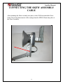
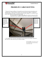
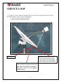
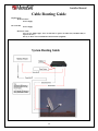
1
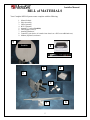
MESA
FIXED AUTOMATIC
// MESA
PRODELIN
Installer Manual
Rev 23 June ‘10
901-MESA Prodelin Installation
Installer Manual
WHAT IS A MESA
The MESA is a three (3) axis (Azimuth, Elevation and Skew) Automatic Fixed Mounting
system.
The MESA is an Automatic Fixed mount system and is designed for a variety of
applications.
•
•
•
•
•
•
•
•
It can automatically track Incline Orbital Satellites
It is pole mounted but can be directed to other satellites at will.
It provides flexibility to allow the end user to go from one satellite to another to
take advantage of bandwidth or services using the same IP address.
It gives you the flexibility of a Mobile system but at a fraction of the cost.
Automatic alignment and realignment.
Easily transportable from site to site.
Redundant satellite service (moving to one or more other satellites) can now be
achieved by the customer with out a trained certified technician on site.
On-demand service is now available based on customer requirements.
2
Installer Manual
•
FEATURES
•
•
•
•
•
Three (3) axis automation (Azimuth, Elevation and Skew)
Will track Incline Orbit Satellites in Azimuth and Elevation
Available in 1.2 Meter dish (1.8 meter available mid 2010)
Prodelin
Andrews
Motor operation directed and operated through the coax cables
Motor power is 12 VDC and is supplied by a 2 conductor cable that is connected to
the MESA Controller. An Optional 12 VDC battery may be ordered when
installations do not allow a run of the 2 conductor cable. The battery is located on the
mount and is recharged through the Rx coax cable. The battery is an option and is not
required.
SPECIFICATIONS
Electrical Interface
F Type connector ODU PCB with 12V external power or Optional 12V Battery
supply
DiSEQ Communications to IDU
Motors
Azimuth 12V 1 Amp (operational)
Elevation 12V 2.5 Amp (operational)
Polarization 12V 1 Amp (operational)
Mount Rotation
Azimuth 280 Degrees
Elevation 10 to 89 degrees
Azimuth Tracking Speed .333 degrees per second
Elevation Tracking Speed .080 degrees per second
Mechanical
Azimuth Gear reduced Worm Drive +/- degree
Peaking resolution Linear +/-.025 degree
Elevation Acme screw drive +/- .1 degree
Polarization chain reduced direct drive +/- .25 degree
Physical
Mount assembly weight without antenna 34 lbs.
Environmental
Wind Operational (see antenna specs)
Wind survival (see antenna specs)
BUC (see BUC specs)
LNB (see LNB specs)
Cable Run Limitations
RG6 – Solid Copper up to 250 ft. Longer runs will require RG11
3
Installer Manual
Table of Contents
BILL of MATERIALS
5
CAUTIONS
6
INSTALLATION
7
MOUNT ALIGNMENT
8
DISH ATTACHMENT
8
FEED (TRIA) HOLDER ASSEMBLY
CABLING TX/RX and SKEW
SKEW ASSEMBLY
GENERAL CABLE ROUTING
SERVICE LOOP
9
CABLE ROUTING GUIDE
14
OPTIONAL MOUNT POWER CABLE
15
RECAP
16
THINGS “TO DO/NOT TO DO”
17
PART NUMBER BREAKDOWN
18
MESA TERMINOLOGY
19
WARRANTY
20
SUPPORT
22
4
Installer Manual
BILL of MATERIALS
Your Complete MESA System comes complete with the following
1.
2.
3.
4.
5.
6.
7.
8.
9.
Mount Pedestal
Skew Assembly
LNB (Optional)
BUC (Optional)
Antenna. 1.2 meter (Prodelin)
LNB Support Arms (3)
Attaching Hardware
Controller (your choice of a stand-a-lone chassis or a 1RU at an additional cost.)
Modem (Optional) not shown.
5
Prodelin
8
Optional 1RU
4
3
1
2
7
5
6
Installer Manual
CAUTIONS:
INSTALLATION POLE HEIGHT
The pole must be tall enough that the dish face will clear any structure or
obstacle that it may encounter. Restriction of the movement in such a manner
could cause damage to the dish face, mount or both. It is up to the installing
personnel to assure that proper clearances are maintained.
CONTROLLER SETTINGS
Prodelin reflectors require an 8 degree “Elevation Origin” setting in the
controller. This adjustment is pre-set in the controller by MotoSAT's final
inspection group when the system ships from MotoSAT. If a customer does an
"NV clear" command which sets the controller back to factory settings (which it
does just that), the “Elevation Origin” setting will be set back to zero. The
Prodelin MESA system will not function optimally. If the “Elevation Origin” is
not set to 8 degrees when using a Prodelin reflector, the customer's search times
will increase significantly. Consult your controller’s Operation Manual for further
detail.
6
Installer Manual
INSTALLATION
1.
2.
Installation begins with a Ground Pole which must be 3” OD (Out side Diameter.) Any
mounting pole larger than this will not accommodate the MESA Mount Pedestal. It must
be hollow at lease 4 inches down from the top of the pole. Pipe thickness does not
matter. We recommend that the pole be tall enough in height to keep the transmitter out
of a child’s reach.
Start by placing the MESA Mount Pedestal on the mounting pole.
7
Installer Manual
MOUNT ALIGNMENT
3. IMPORTANT!! Orient the flat surface of the underside of the Mount WEST.
Insert the
six (6) Mount Retaining Screws into the base and tighten completely. There is no more
positioning of the mount that is required from this time forward.
WEST for NORTHERN HEMISPHERE
EAST for SOUTHERN HEMISPHERE
Mount Retaining
Screws at 6 locations
around the mounting
pipe.
DISH ATTACHMENT
4.
When using the Carriage Bolts supplied, locate the four (4) mounting holes and with a 3/8
inch drill bit, drill them out from the back side of the dish through to the front. If you use the HiLo self tapping screws that attach from the rear DO NOT DRILL OUT THESE HOLES.
PRODELIN DISH
8
Installer Manual
FEED (TRIA) ASSEMBLY
Route the RX/TX coax and Skew Motor
cables up and through the TRIA channel.
Color coded coax
White = TX / Black = RX
Skew Assembly Brackets
9
Installer Manual
Transmit (RT), Receive (RX) and Skew cable Routing
Route the Transmit cable to the BUC (TX) and the Receive cable to the LNB (RX). The BUC
and LNB have been shipped with a protective cap that has a small amount of Dielectric grease
inside. Remove the cap and place the grease inside of your RG6 connectors and attach to the
components. Note: It is easy to confuse these two cables. Make sure the Transmit (TX) is
attached to the BUC and the Receive (RX) is attached to the LNB.
LNB
BUC
SKEW
Assembly
10
Installer Manual
CONNECTING THE SKEW ASSEMBLY
CABLE
After mounting the Skew assembly into place on the LNB Arm attach the Skew
Cable Twist Lock Interconnect cable coming from the MESA Mount into place at
the Skew Assembly.
11
Installer Manual
PRODELIN CABLE ROUTING
1.
Route the Transmit and Receive Coax cables from the facility that houses the modem to the
installation pole. Connect the Receive (RX) Coax to the pig tail coax (approx 2’ long) that is
currently attached to the mount. Use the barrel connector that is supplied. Use a dielectric jell or
grease at this connection to prevent moisture damage.
(The pig tailed RG6 is the Receive line (RX) and it continues in route to the LNB
along with the Skew Assembly Cable that will be connected to the Skew Motor.)
The White TX
cable will be
routed up the
Center LNB
Support Arm to
the Transmitter
(BUC)
The Black RX
Cable will be
routed up the
Center LNB
Support Arm
to the LNB.
Things that are critical
2. The Transmit (TX) Cable that comes directly from the modem will accompany the Receive
(RX) and Skew cable on their way to the TRIA Assembly.
The TX and RX cables should be routed
the around the mount to insure that they
do not bind or catch.
12
Installer Manual
SERVICE LOOP
3. The Receive Coax, Transmit Coax and the Skew Cable must be wrapped and tied in a loop in
the manner shown. There is a two (2) fold purpose.
a. Service loop for possible future needs.
b. Slack for mount rotational purposes.
RAVEN Antenna shown
Black cable is the Receive cable
that came from the facility and is
connected to the pig tail that goes
to the LNB by way of the Mount.
Service Loop
White cable is the Transmit cable that
comes from directly from the modem and
goes directly to the BUC (transmitter.)
Gray cable is the Skew cable that goes to
the Skew motor.
13
Installer Manual
Cable Routing Guide
Requirements
Modem of choice
Power Supply
D4 Controller
Power Supply
RG6 Coax Cable
Two (2) coax, Solid Copper, not to exceed 250’ ea. (prefer one white (TX) and black (RX) to
separate the two.)
One (1) 2’ RG 6 coax from Modem to D4 Controller (supplied)
14
Installer Manual
OPTIONAL Mount Power Cable
If your MESA Mount has a plug ( not a plug with a cable attached) then you have a battery with
your system. It can be operated with or without a Mount Power Cable if you have a battery. If your system
does not have a battery then the Mount Power Plug (and cable) is required.
Your MESA system comes standard with a battery designed into the mount. The battery is charged and the
operation of the mount is done through the RX coaxial cable. The battery provides power to the motors (Azimuth,
Elevation and Skew) from a command given by the controller through the RX coaxial cable. The battery charge is
maintained by the modem. There may be occasions or conditions where a battery is not wanted. In that case we
have designed a Mount Power Cable which will eliminate the battery. When used, the power to the motors would
be provided by the MESA Controller through the two (2) conductor cable which is run from the MESA Controller to
the mount. A typical hookup for the Mount Power Cable is described below:
110-220 VAC
Two (2) Conductors
Pin 6 = Ground (Black)
Pin 9 = 12-18 VDC (Red)
15 VDC Power Supply
Battery Connect Plug (is used
when a battery has been installed).
To use the Mount Power Cable remove the
Battery Connect Plug and replace it with the
Mount Power Cable.
15
Installer Manual
RECAP
WEST – (Northern Hemisphere)
EAST – (Southern Hemisphere)
RT, RX and Skew cables secure?
YOU SHOULD BE GOOD TO GO IF
•
•
•
•
•
•
•
Are all connections secured?
Are all mounting bolts secured?
Does the RT cable go from BUC directly to the modem?
Does the RX cable go from the LNB to the MESA controller and then to the
modem?
Is the mount orientated in accordance to specifications?
Are your coax and skew cables positioned in such a way as to not catch on anything
during rotation?
Are all cable connections protected with dielectric jell or grease?
16
Installer Manual
THINGS YOU SHOULD
And
SHOULD NOT DO
1. Never apply power directly to the Azimuth, Elevation or Skew
Motors. Doing so will send current directly to the Mount Control
Board and cause electrical damage. If you have a requirement to run
these motors directly, please contact our Technical Support
department for suggestions.
2. Always tighten the mount bolts on the mounting pole evenly and
firmly so that the mount will not rock or twist on the pole. It is
recommended that a pin be placed through the MESA Mount into the
ground pole to prevent the mount from twisting during severe winds.
3. Loop the Transmit and Receive coax cables that come from the
modem onto the mount in such a way as to not create tension on the
cable when rotating and searching for satellite.
4. Loop the RX and TX coaxial cables coming directly from the BUC
and LNB in such a way as to allow for rotation of the TRIA Assembly
and not stress the cable or connectors.
5. Position the RX and TX coaxial cables so that they will not catch on
the bolts that hold the mount onto the mounting pole during antenna
rotation.
6. Secure all loose cables with cable ties where possible.
17
Installer Manual
18
Installer Manual
MESA Terminology
Dish Mounting Plate
Elevation All-Thread inside
bellows
RX Cable (to LNB), Skew
Cable (to Skew Motor)
Elevation Motor under cover
Azimuth Motor under cover
Battery Cover
Skew Cable Connection
Mount Power Plug
RX Coax Cable to MESA
Controller
19
Installer Manual
MESA
LIMITED WARRANTY
(1 YEAR PARTS / 1 YEAR LABOR)
MotoSAT warrants this product against defects in materials or workmanship for a period of one (1)
year and against factory labor costs for a period of one (1) year from the date of original purchase by
the original purchaser. (This warranty is non-transferable).
It is the customer’s responsibility to verify the date of purchase by registering the product with
MotoSAT within thirty (30) days of purchase. If the date of purchase cannot be verified, the
warranty period will begin thirty (30) days after the product’s date of manufacture.
If a defect in material, workmanship, or product performance, according to specifications, is
discovered during the warranty period, the customer should contact their distributor or MotoSAT
technical support. If the product cannot be repaired at the customer’s location, MotoSAT will, at its
option, repair or replace the product at no charge to the customer, provided the customer returns
the product to MotoSAT, during the warranty period with transportation charges prepaid. The
customer must return the product with the return material authorization (RMA) number clearly
marked on the outside of the container. MotoSAT will ship the product back to customer, ground
transportation prepaid. If an expedited return delivery is desired, all additional transportation
charges will be the sole responsibility of the customer.
Third party manufactured equipment including satellite modems, LNB’s, BUC’s, BUC power
supplies, special cables, outdoor antenna components and any other non-MotoSat manufactured
items will be covered by the original manufacturer’s warranty only.
Approval of the warranty service is at the sole discretion of MotoSAT. MotoSAT reserves the right
to utilize refurbished or remanufactured parts in its product manufacturing and repair activities
provided such parts conform to MotoSAT’s specifications for new products and/or parts.
This limited warranty does not apply if the product has been damaged by accident, abuse, misuse, or
malfunctions as a result of improper installation or misapplication, modification of the product as
originally manufactured by MotoSAT in any manner whatsoever, removing or defacing any serial
number, usage not in accordance with product instructions or acts of nature such as damage caused
by wind, lightning, ice or corrosive environments such as salt spray and acid rain. This limited
warranty also does not apply if the product becomes unable to perform its intended function in any
way as a result of the bandwidth service provider making any changes in technology or service.
This warranty can be extended through the purchase of an extended warranty. Note that if you
choose the 1.2m MESA with the battery option, the battery will not be covered by the extended
warranty. The expected battery life is 2 to 5 years. Spare batteries are available for purchase from
MotoSAT.
During the term of this contract, all software updates for the MESA will be made available to the
customer.
20
Installer Manual
RETURN AUTHORIZATION POLICY
A return material authorization (RMA) is required prior to returning any product to MotoSAT.
Please call our technical support department at 800-247-7486 or send an e-mail to
[email protected] in order to obtain the RMA number. Please provide contact
information and serial number of the product when requesting an RMA number. If possible, use
the original box and packing material to protect the product from damage during transportation.
Enclose the product in a prepaid package and write the RMA number in large, clear letters on the
outside of the package. To avoid confusion or misunderstanding, shipments without an RMA
number or unauthorized returns will be refused and returned to the customer freight collect.
MOTOSAT DOES NOT ASSUME ANY LIABILITIES FOR ANY OTHER WARRANTIES,
EXPRESS OR IMPLIED, MADE BY ANY OTHER PERSON. ALL OTHER WARRANTIES
WHETHER EXPRESS, IMPLIED OR STATUTORY INCLUDING WARRANTIES OF
FITNESS FOR A PARTICULAR PURPOSE AND MERCHANTABILITY ARE LIMITED TO
THE ONE YEAR PERIOD OF THIS WARRANTY.
MotoSAT’s liability in contract, tort or otherwise arising out of or in connection with any product
shall not exceed the price paid for the product. IN NO EVENT SHALL MOTOSAT BE LIABLE
FOR SPECIAL, PUNITIVE, INCIDENTAL, TORT OR CONSEQUENTIAL DAMAGES OR
LOST PROFITS OR GOODWILL (INCLUDING ANY DAMAGES RESULTING FROM
LOSS OF USE, DELAY IN DELIVERY OR OTHERWISE) ARISING OUT OF OR IN
CONNECTION WITH THE PERFORMANCE OR USE OR POSSESSION OF ANY
PRODUCT, OR ANY OTHER OBLIGATIONS RELATING TO THE PRODUCT, EVEN IF
MOTOSAT HAS BEEN ADVISED OF THE POSSIBILITY OF SUCH DAMAGES.
EXTENDED WARRANTY IS AVAILABLE
THOUGH YOUR SUPPLIER.
An Extended Warranty may be purchased to extend the original warranty after the first year for up to a total of
three (3) years from date of purchase.
All terms and conditions of the original “1 YEAR PARTS / 1 YEAR LABOR” apply to the “Extended
Warranty.”
Contact your supplier for details.
21
Installer Manual
22
Installer Manual
SUPPORT
For Technical Support please call
1-800-247-7486
Ask for the next available Technician
or Email
[email protected]
MotoSAT
1955 South Milestone Dr.
Salt Lake City, UT 84104
www.motosat.com
23