1
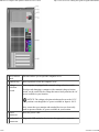
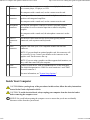
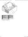
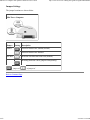
Mini Tower Computer: Dell OptiPlex GX620<br>User's Guide
1 of 8
http://www.zoion.com/~erlkonig/misc/gx620-userguide/mtabout0.htm
Back to Contents Page
Mini Tower Computer
Dell™ OptiPlex™ GX620
User's Guide
About Your Mini Tower Computer
Inside Your Computer
About Your Mini Tower Computer
Front View
1
CD/DVD
drive
Insert a CD or DVD (if applicable) into this drive.
2/27/2011 12:36 PM
Mini Tower Computer: Dell OptiPlex GX620<br>User's Guide
2 of 8
http://www.zoion.com/~erlkonig/misc/gx620-userguide/mtabout0.htm
2
floppy drive
Insert a floppy disk into this drive.
3
USB 2.0
connectors
(2)
Use the front USB connectors for devices that you connect
occasionally, such as joysticks or cameras, or for bootable USB devices
(see "System Setup" for more information on booting to a USB device).
It is recommended that you use the back USB connectors for devices
that typically remain connected, such as printers and keyboards.
4
LAN
This light indicates that a LAN (network) connection is established.
indicator light
5
diagnostic
lights
Use the lights to help you troubleshoot a computer problem based on
the diagnostic code. For more information, see "Diagnostic Lights."
6
power button
Press this button to turn on the computer.
NOTICE: To avoid losing data, do not turn off the computer by pressing
the power button for 6 seconds or longer. Instead, perform an operating
system shutdown.
NOTICE: If your operating system has ACPI enabled, when you press
the power button the computer will perform an operating system
shutdown.
7
power light
The power light illuminates and blinks or remains solid to indicate
different operating modes:
No light — The computer is turned off.
Steady green — The computer is in a normal operating state.
Blinking green — The computer is in a power-saving mode.
Blinking or solid amber — See "Power Problems."
To exit from a power-saving mode, press the power button or use the
keyboard or the mouse if it is configured as a wake device in the
Windows Device Manager. For more information about sleep modes
and exiting from a power-saving mode, see "Power Management."
See "Diagnostic Lights" for a description of light codes that can help
you troubleshoot problems with your computer.
8
hard-drive
activity light
This light will flicker when the hard drive is being accessed.
9
headphone
connector
Use the headphone connector to attach headphones and most kinds of
speakers.
10 microphone
connector
Use the microphone connector to attach a microphone.
Back View
2/27/2011 12:36 PM
Mini Tower Computer: Dell OptiPlex GX620<br>User's Guide
3 of 8
http://www.zoion.com/~erlkonig/misc/gx620-userguide/mtabout0.htm
1 cover release
latch
This latch allows you to open the computer cover.
2 padlock ring
Insert a padlock to lock the computer cover.
3 voltage
selection
switch
Your computer is equipped with a manual voltage selection switch.
To help avoid damaging a computer with a manual voltage selection
switch, set the switch for the voltage that most closely matches the AC
power available in your location.
NOTICE: The voltage selection switch must be set to the 115-V
position even though the AC power available in Japan is 100 V.
Also, ensure that your monitor and attached devices are electrically
rated to operate with the AC power available in your location.
4 power
connector
Insert the power cable.
5 back-panel
connectors
Plug serial, USB, and other devices into the appropriate connector.
2/27/2011 12:36 PM
Mini Tower Computer: Dell OptiPlex GX620<br>User's Guide
4 of 8
6 card slots
http://www.zoion.com/~erlkonig/misc/gx620-userguide/mtabout0.htm
Access connectors for any installed PCI and PCI Express cards.
Back-Panel Connectors
1
parallel
connector
Connect a parallel device, such as a printer, to the parallel connector. If
you have a USB printer, plug it into a USB connector.
NOTE: The integrated parallel connector is automatically disabled if the
computer detects an installed card containing a parallel connector
configured to the same address. For more information, see "System
Setup Options."
2
link integrity
light
3
network
adapter
connector
Green — A good connection exists between a 10-Mbps network
and the computer.
Orange — A good connection exists between a 100-Mbps
network and the computer.
Yellow — A good connection exists between a 1-Gbps (or
1000-Mbps) network and the computer.
Off — The computer is not detecting a physical connection to the
network.
To attach your computer to a network or broadband device, connect
one end of a network cable to either a network jack or your network or
broadband device. Connect the other end of the network cable to the
network adapter connector on the back panel of your computer. A click
indicates that the network cable has been securely attached.
NOTE: Do not plug a telephone cable into the network connector.
On computers with a network connector card, use the connector on the
card.
It is recommended that you use Category 5 wiring and connectors for
your network. If you must use Category 3 wiring, force the network
speed to 10 Mbps to ensure reliable operation.
4
network
activity light
Flashes a yellow light when the computer is transmitting or receiving
network data. A high volume of network traffic may make this light
appear to be in a steady "on" state.
2/27/2011 12:36 PM
Mini Tower Computer: Dell OptiPlex GX620<br>User's Guide
5 of 8
5
line-in
connector
http://www.zoion.com/~erlkonig/misc/gx620-userguide/mtabout0.htm
Use the blue line-in connector to attach a record/playback device such
as a cassette player, CD player, or VCR.
On computers with a sound card, use the connector on the card.
6
line-out
connector
Use the green line-out connector to attach headphones and most
speakers with integrated amplifiers.
On computers with a sound card, use the connector on the card.
7
microphone
connector
Use the pink microphone connector to attach a personal computer
microphone for voice or musical input into a sound or telephony
program.
On computers with a sound card, the microphone connector is on the
card.
8
USB 2.0
connectors
(6)
Use the back USB connectors for devices that typically remain
connected, such as printers and keyboards.
9
video
connector
Plug the cable from your VGA-compatible monitor into the blue
connector.
NOTE: If you purchased an optional graphics card, this connector will
be covered by a cap. Connect your monitor to the connector on the
graphics card. Do not remove the cap.
NOTE: If you are using a graphics card that supports dual monitors, use
the y-cable that came with your computer.
10 serial
connector
Connect a serial device, such as a handheld device, to the serial port.
The default designations are COM1 for serial connector 1 and COM2
for serial connector 2.
For more information, see "System Setup Options."
Inside Your Computer
CAUTION: Before you begin any of the procedures in this section, follow the safety instructions
located in the Product Information Guide.
CAUTION: To avoid electrical shock, always unplug your computer from the electrical outlet
before removing the computer cover.
NOTICE: Be careful when opening the computer cover to ensure that you do not accidentally
disconnect cables from the system board.
2/27/2011 12:36 PM
Mini Tower Computer: Dell OptiPlex GX620<br>User's Guide
6 of 8
1 CD/DVD drive
5 system board
2 floppy drive
6 heat sink assembly
3 power supply
7 hard drive
http://www.zoion.com/~erlkonig/misc/gx620-userguide/mtabout0.htm
4 chassis intrusion switch
System Board Components
2/27/2011 12:36 PM
Mini Tower Computer: Dell OptiPlex GX620<br>User's Guide
7 of 8
http://www.zoion.com/~erlkonig/misc/gx620-userguide/mtabout0.htm
1
fan connector (FAN)
12 password jumper (PSWD)
2
processor connector (CPU)
13 battery socket (BATT)
3
power connector (12VPOWER)
14 PCI Express x16 connector
(SLOT1)
4
memory module connectors (DIMM_1, DIMM_2, DIMM_3,
DIMM_4)
15 PCI Express x1 connector
(SLOT4)
5
serial ATA drive connectors (SATA0, SATA2, SATA1, SATA3)
16 PCI connector (SLOT2)
6
front-panel connector (FNT_PANEL)
17 PCI connector (SLOT3)
7
CD drive analog audio cable connector for optional analog audio
cable (CD_IN)
18 serial connector (SER2)
8
power connector (POWER)
19 floppy drive connector (DSKT)
9
CD/DVD drive connector (IDE)
20 standby power indicator
(AUX_PWR)
10 RTC reset jumper (RTCRST)
21 system board speaker (BEEP)
11 intrusion switch connector (INTRUDER)
22 internal speaker (INT_SPKR)
2/27/2011 12:36 PM
Mini Tower Computer: Dell OptiPlex GX620<br>User's Guide
8 of 8
http://www.zoion.com/~erlkonig/misc/gx620-userguide/mtabout0.htm
Jumper Settings
The jumper locations are shown below.
Mini Tower Computer
Jumper
Setting Description
PSWD
Password features are enabled (default).
Password features are disabled.
RTCRST
Real-time clock has not been reset (default).
Resetting Real-time clock (jumpered temporarily).
jumpered
unjumpered
Back to Contents Page
2/27/2011 12:36 PM